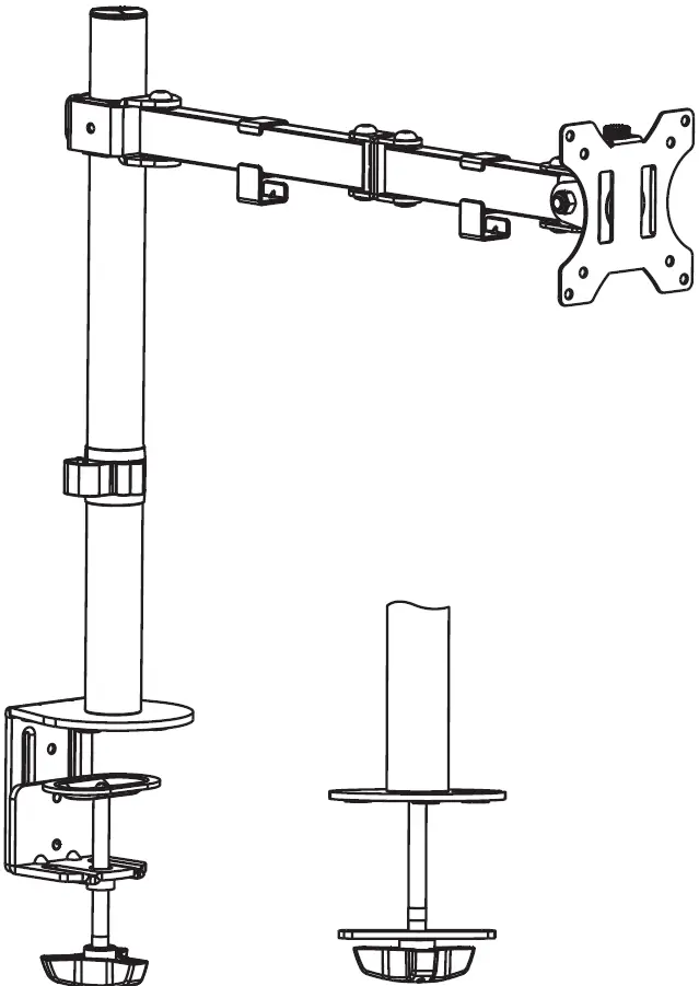
WALI Single Monitor Desk Mount
WARNING:
If you do not understand these directions, or if you have any doubts about the safety of the installation, please call a qualified technician. Check carefully to make sure there are no missing or defective parts. Improper installation may cause damage or serious injury. Do not use this product for any purpose that is not explicitly specified in this manual.
Do not exceed weight capacity. We cannot be liable for damage or injury caused by improper mounting, incorrect assembly or inappropriate use.
SERIOUS OR FATAL CRUSHING INJURIES CAN OCCUR FROM TIPOVER. TO HELP PREVENT TIPOVER:
- NEVER ALLOW CHILDREN TO CLIMB, STAND, HANG, OR PLAY ON ANY PART OF MONITOR OR STAND.
- USE TIPOVER RESTRAINT OR ANCHOR STAND TO WALL.
Supplied Parts List
How to Assemble
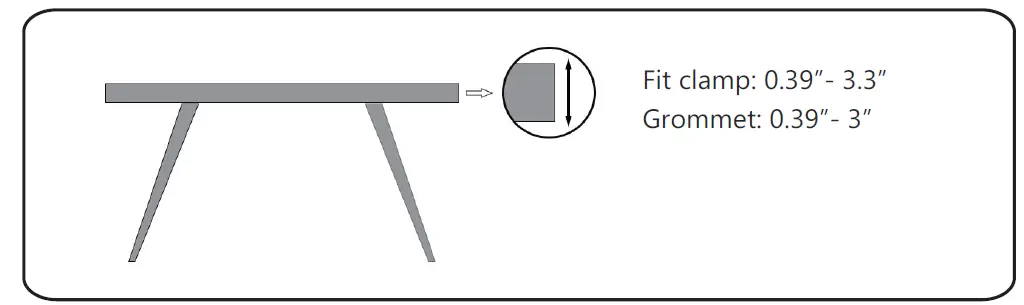
Step1: Measure the thickness of your mounting surface or desk
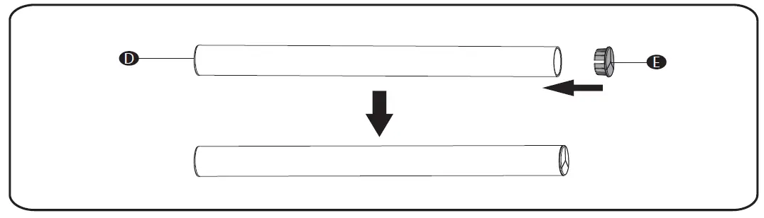
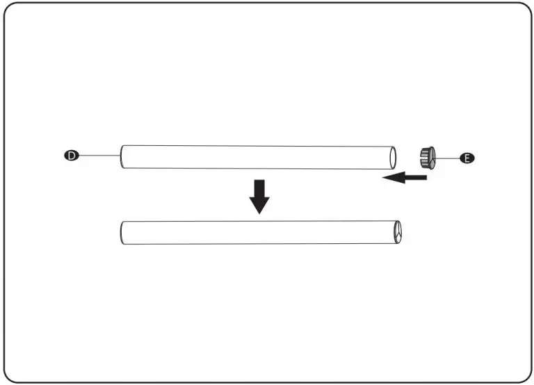
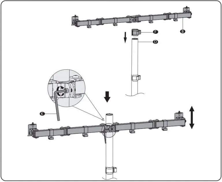
Step2: Press Pole Cover E into the top of Pole D
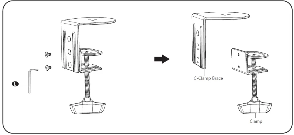
Step3: Loosen the bolts on C-Clamp C using Allen Key 4mm L
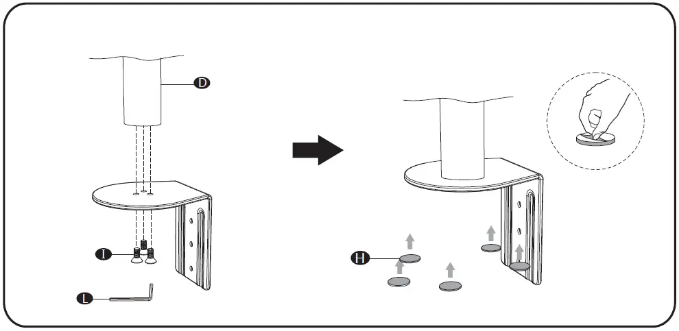
Step4:
Option A : Clamp Installation
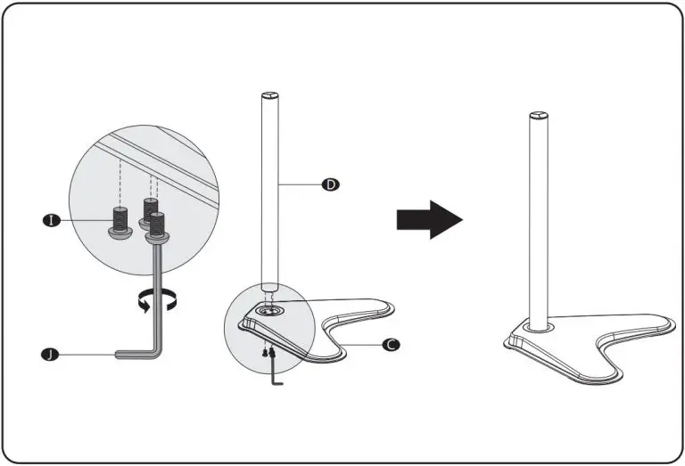
- Connect Pole D and C-Clamp Brace from the bottom using M6x12 Bolt I and tighten with Allen Key 4mm L .Tear off the protect paper and attach Anti-Skid Pads H to the bottom designated position of C-Clamp Brace as image shown.
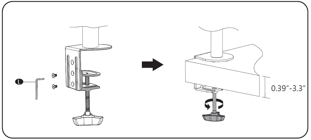
- Connect C-Clamp to C-Clamp Brace using the bolts and tighten with Allen Key 4mm L . Rotate the hand knob clockwise to fasten for stability.
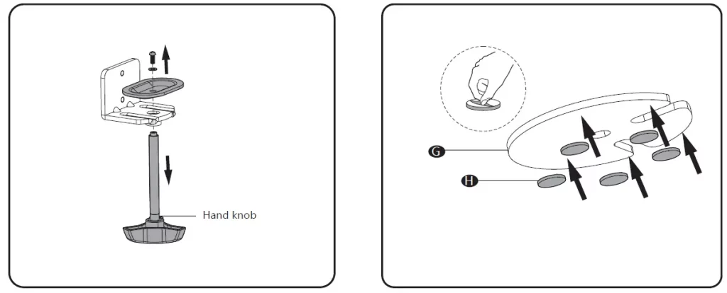
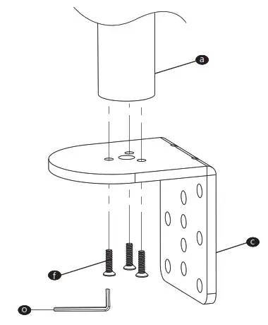
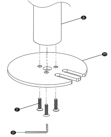
Option B: Grommet Base Installation
- Loosen the screw to release the hand knob using a screwdriver as image shown. (Screwdriver not included)
- Tear off the protect paper and attach Anti-Skid Pads H to the bottom designated position of Grommet Base Plate G as image shown.
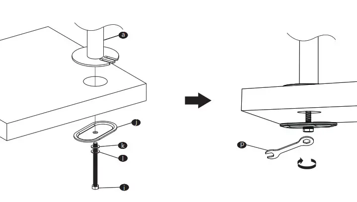
- Existing Grommet Hole Installation
If the existing grommet hole comes with a plastic protector, remove it to ensure a flat surface before installing the desk mount. Place the Grommet Base Plate G and Pole D to the grommet hole. Insert the hand knob through the center hole of Support Plate J and desk hole, rotate the hand knob clockwise to fasten for stability.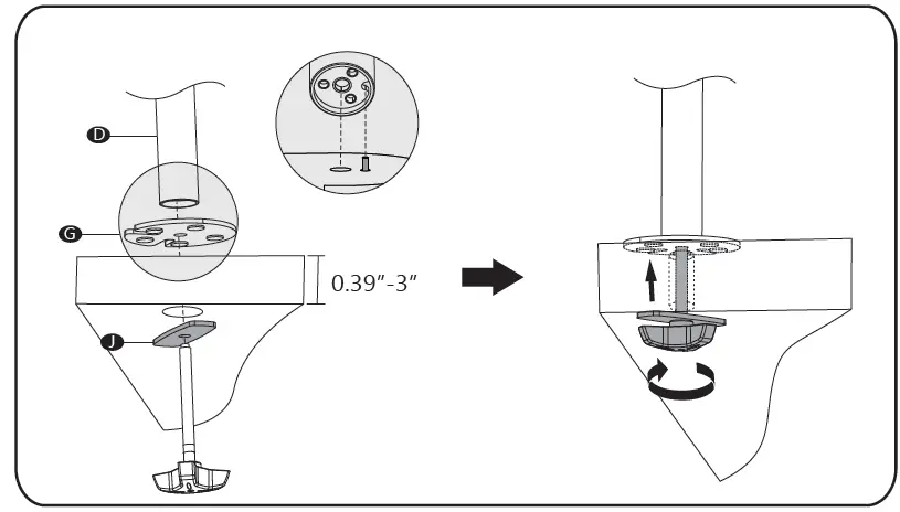
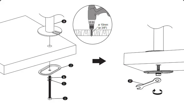
- Self-drilled Grommet Hole Installation
Mark the position of the hole on your mounting surface. Drill a 3/8″(10mm) diameter hole at the marked position through the mounting surface. Place the Grommet Base Plate G and Pole D to the grommet hole. Insert the hand knob through the center hole of Support Plate J and desk hole, rotate the hand knob clockwise to fasten for stability.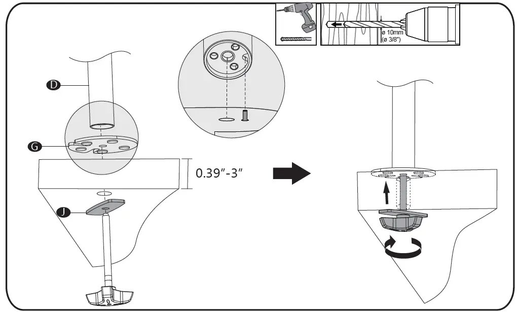
Step5: 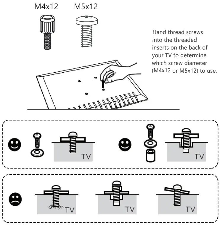
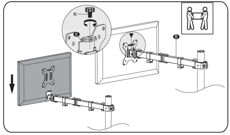
Step6: Put the Tool Holder F and Arm B through the Pole D , adjust the preferred height and tighten using Allen Key 6mm M .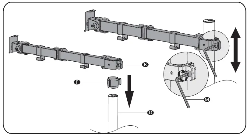
Step7: Put the assembled TV/Monitor onto the Arm B and ensure stability, tighten the VESA plate using Top Screw K .
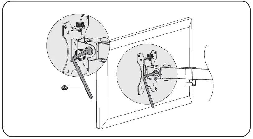
Step8: Adjust the tilt angle using Allen Key 6mm M .
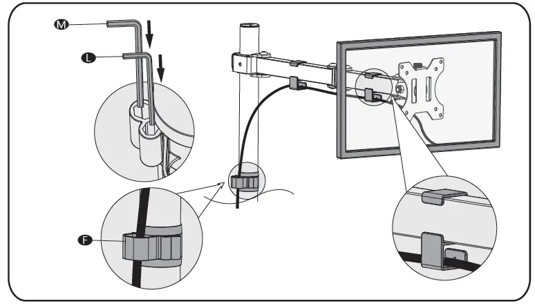
Step9: Guide the cable through the Tool Holder F and wire clips. Store the Allen Keys in the Tool Holder F .
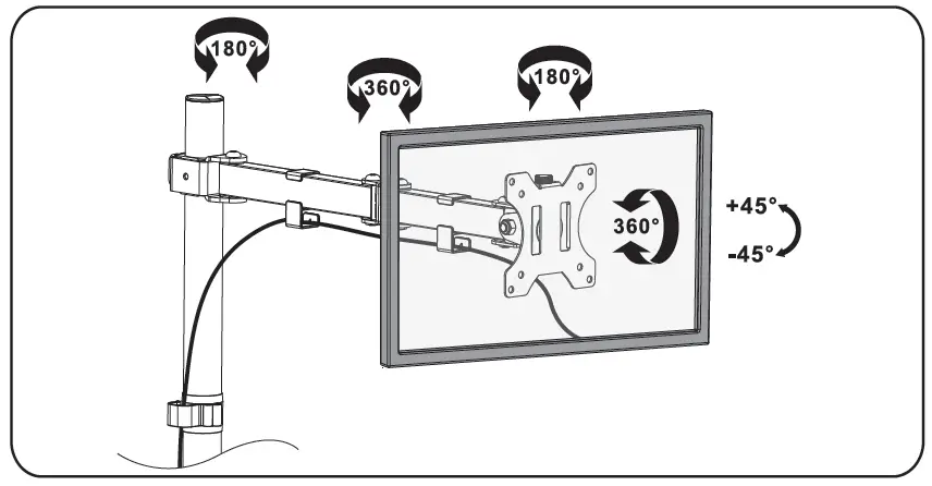
Step10: Manually swivel, tilt, and rotate the monitor for the best viewing angle.

MF002LM
WARNING
If you do not understand these directions, or if you have any doubts about the safety of the installation, please call a qualified technician. Check carefully to make sure there are no missing or defective parts. Improper installation may cause damage or serious injury. Do not use this product for any purpose that is not explicitly specified in this manual. Do not exceed weight capacity. We cannot be liable for damage or injury caused by improper mounting, incorrect assembly or inappropriate use.
TIPOVER WARNING
SERIOUS OR FATAL CRUSHING INJURIES CAN OCCUR FROM TIPOVER. TO HELP PREVENT TIPOVER:
- NEVER ALLOW CHILDREN TO CLIMB, STAND, HANG, OR PLAY ON ANY PART OF MONITOR OR STAND.
- USE TIPOVER RESTRAINT OR ANCHOR STAND TO WALL.
USE OF TIPOVER RESTRAINTS MAY ONLY REDUCE, BUT NOT ELIMINATE RISK OF TIP OVER.
SMALL PARTS- NOT FOR CHILDREN UNDER 3 YEARS. ADULT SUPERVISION IS REQUIRED.
Supplied Parts List
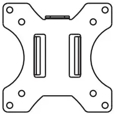
- VESA Plate A (x2)

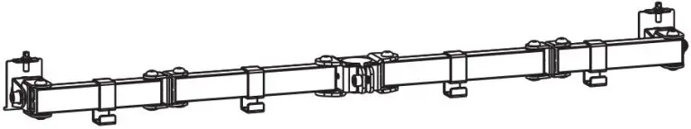
- Arm B (x1)
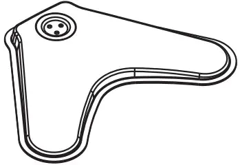
- V-Shape Base C (x1)
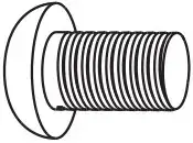
- Pole D (x1)
- Pole Cover E (x1)

- Tool Holder F (x1)
- Nut G (x2)
- M3x7 Bolt H (x2)
- M6x13 Bolt I (x3)
- Allen Key 4mm J (x1)
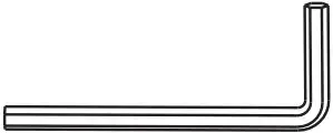
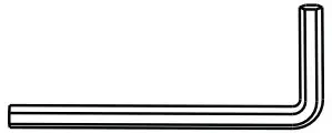
- Allen Key 6mm K (x1)
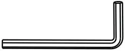
- Allen Key 5mm L (x1)
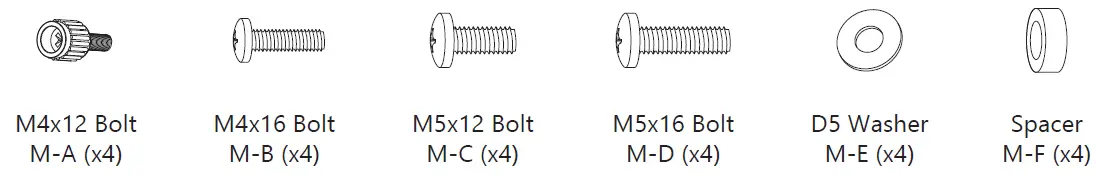
- M4x12 Bolt M-A (x8)
- M4x16 Bolt M-B (x8)
- M5x12 Bolt M-C (x8)
- M5x16 Bolt M-D (x8)
- D5 Washer M-E (x8)
- Spacer M-F (x8)
Assembly Instructions
- Press Pole Cover E into the top of Pole D.
- Install the Pole D to the V-Shape Base C using M6x13 Bolts I and tighten with Allen Key 4 mm J.
- Put the Tool Holder F and Arm B through the Pole D, adjust the preferred height and tighten using Allen Key 6mm K.
- Steps
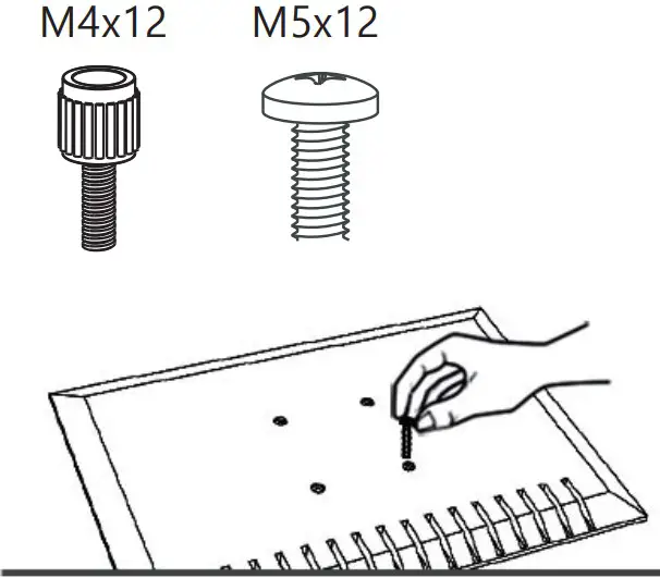
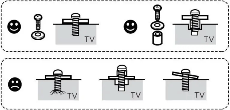
- Select TV Screws
Only one screw size fits your TV
Hand thread screws into the threaded inserts on the back of your TV to determine which screw diameter (M4x12 or M5x12) to use.
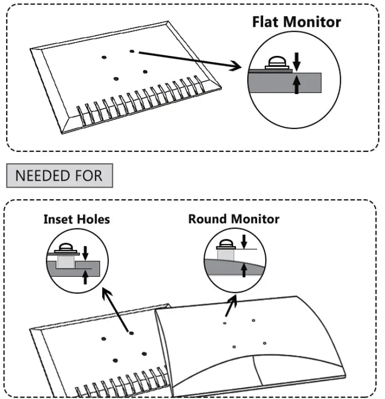
- Select Spacers ( if needed )
NOT NEEDED
NEEDED FOR
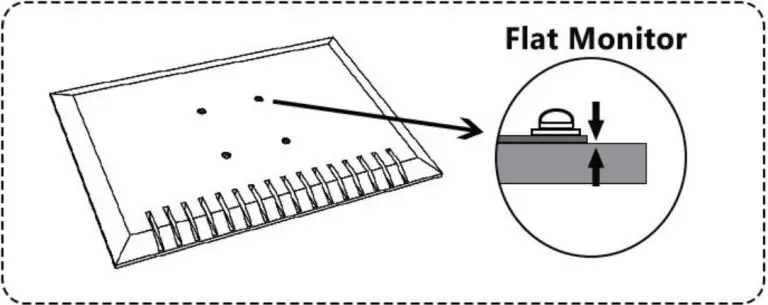
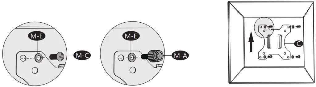
- Flat Back Monitor
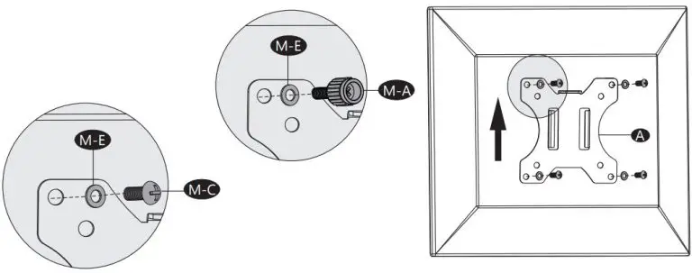
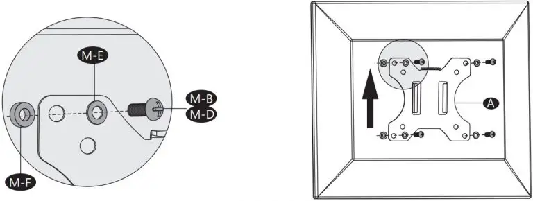
Select M4x12 Bolt M-A or M5x12 Bolt M-C according to your TV/Monitor, connect VESA Plate A together with D5 Washer M-E into the mounting holes on the back of TV/Monitor, tighten with a screwdriver. (Screwdriver not included)
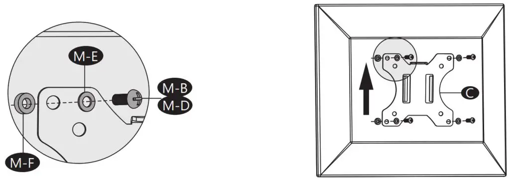
- Curved Back Monitor
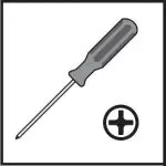
Select M4x16 Bolt M-B or M5x16 Bolt M-D according to your TV/Monitor, connect VESA Plate A together with D5 Washer M-E and Spacer M-F into the mounting holes on the back of TV/Monitor, tighten with a screwdriver. (Screwdriver not included)
- Select TV Screws
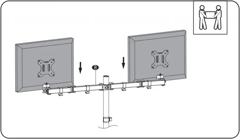
- Put the assembled TV/Monitor onto the Arm B and ensure stability.
- Tighten the VESA plate using Nut G and M3x7 Bolt H with a screwdriver. (Screwdriver not included) Adjust the tilt angle using Allen Key 6mm K.
- Guide the cable through the Tool Holder F and wire clips.
- Store the Allen Keys in the Tool Holder F.
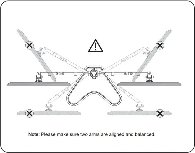
- For safety, please do not extend the arms too far forward or backward. This may cause instability and tip over.
- Manually swivel, tilt, and rotate the monitor for the best viewing angle. Adjust the height of VESA Plate A using Allen Key 6mm K.
Support
Website: www.walielectric.com
Support: [email protected]
Call: 1-844-SATTLER (18447288537)

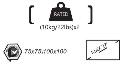
(8kg/17.6lbs)x2

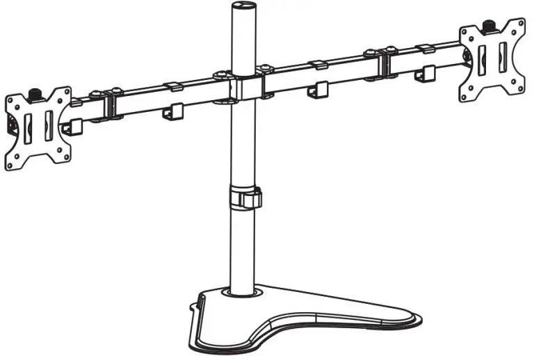
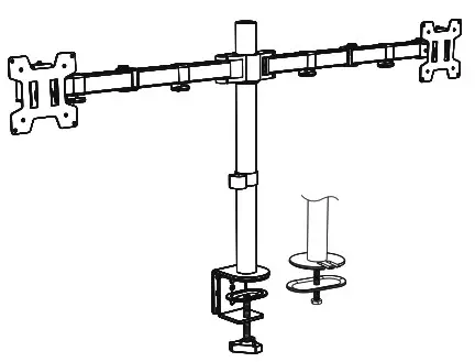
INSTALLATION MANUAL Dual Monitor Desk Mount
M002
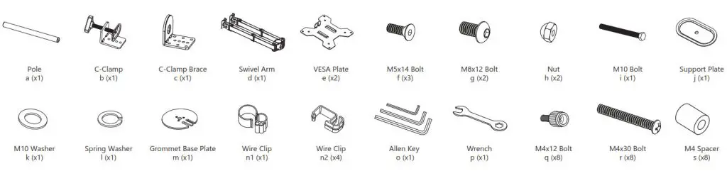
Supplied Parts List
 www.walielectric.com
 [email protected]
 1-844-SATTLER (18447288537)
 WARNING
If you do not understand these directions, or if you have any doubts about the safety of the installation, please call a qualified technician. Check carefully to make sure there are no missing or defective parts. Improper installation may cause damage or serious injury. Do not use this product for any purpose that is not explicitly specified in this manual. Do not exceed weight capacity. We cannot be liable for damage or injury caused by an improper mounting, incorrect assembly or inappropriate use.
TIPOVER WARNING
SERIOUS OR FATAL CRUSHING INJURIES CAN OCCUR FROM TIPOVER. TO HELP PREVENT TIPOVER:
NEVER ALLOW CHILDREN TO CLIMB, STAND, HANG, OR PLAY ON ANY PART OF THE MONITOR OR STAND. USE TIPOVER RESTRAINT OR ANCHOR STAND TO WALL.
USE OF TIP-OVER RESTRAINTS MAY ONLY REDUCE, BUT NOT ELIMINATE THE RISK OF TIP-OVER.
SMALL PARTS- NOT FOR CHILDREN UNDER 3 YEARS. ADULT SUPERVISION IS REQUIRED.
Supplied Parts List

1.Measure the thickness of your mounting surface or desk.
2.Option A: Clamp Installation
- Connect Pole a and C-Clamp Brace c from the bottom using M5x14 Bolt f and tighten with Allen Key 3mm o.
- Select the preferred height according to your desk thickness. Connect C-Clamp b to C-Clamp Brace c using M8x12 Bolt g and tighten with Allen Key 5mm o. Rotate the hand knob clockwise to fasten for stability.
Option B: Grommet Base Installation
- Place Pole a onto Grommet Base Plate m. Connect them from the bottom using M5x14 Bolt f and tighten with Allen Key 3mm o.
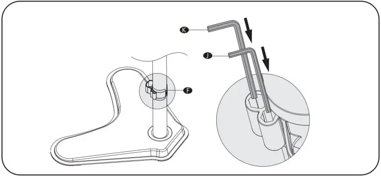
2a. Existing Grommet Hole Installation
If the existing grommet hole comes with a plastic protector, remove it to ensure a flat surface before installing the desk mount. Position the Pole a on the mounting surface and secure using the Support Plate j, M10 Washer k , Spring Washer l , and M10 Bolt i . Fasten the Bolt using the provided Wrench p.
 2b. Self-drilled Grommet Hole Installation
Mark the position of the hole on your mounting surface. Drill a 3/8″(10mm) diameter hole at the marked position through the mounting surface. Position the Pole a on the mounting surface and secure using the Support Plate j, M10 Washer k, Spring Washer l, and M10 Bolt i. Fasten the Bolt using the provided Wrench p.
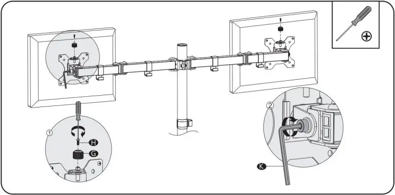
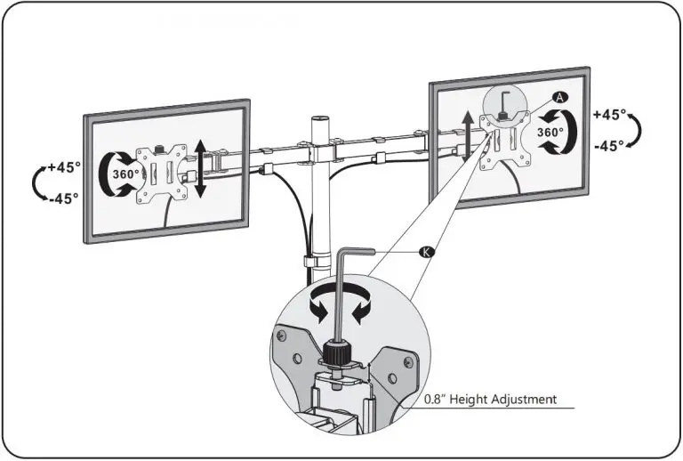
3. Put the Wire Clip n1 and Swivel Arm d through the Pole a , adjust the preferred height, and tighten using Allen Key 6mm o . Attach the Wire Clips n1 to the Swivel Arm d . 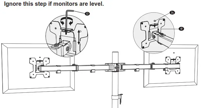
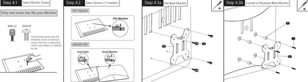
4.Select bolts and spacers (if needed) according to your TV/Monitor. Attach the VESA Plate to the Monitor and tighten with a screwdriver. (Screwdriver not included)
5. Put the assembled TV/Monitor onto the Swivel Arm d and tighten the VESA Plate e with Nut h for stability.
6. If one monitor is lower, remove the Nut h and turn the bolt counter-clockwise using Allen key 3mm o to raise the monitor. Tighten the VESA Plate e with Nut h for stability after the adjustment.
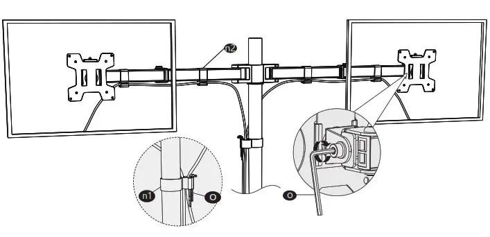
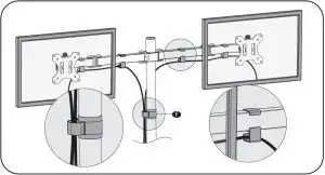
7. Guide the cable through the Wire Clips ( n1, n2 ) and store the Allen Keys o in the Wire Clip n1 . Adjust the tilt angle using Allen Key 5mm n .
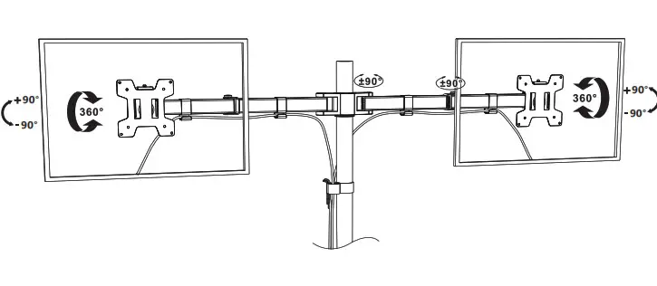
8. Manually swivel, tilt, and rotate the monitor for the best viewing angle.

UNPACKING INSTRUCTIONS
- Carefully open the carton, remove contents and lay out on cardboard or other protective surface to avoid damage .
- Check package contents against the Supplied Parts List in the next page to assure that all components were received undamaged. Do not use damaged or defective parts .
- Carefully read all instructions before attempting installation.
IMPORTANT SAFETY INFORMATION
Install and operate this device with care. Please read this instruction before beginning the installation, and carefully follow all instructions contained herein. Use proper safety equipment during installation.
Please call a qualified installation contractor for help if you:
- If you don’t understand these directions or have any doubts about the safety of the installation .
- If you are uncertain about the nature of your wall, consult a qualified installation contractor. Do not use this product for any purpose or in any configuration not explicitly specified in this instruction. We hereby disclaim any and all liability for injury or damage arising from incorrect assembly, incorrect mounting, or incorrect use of this product.
Su p p l i e d P a r t s L i s t
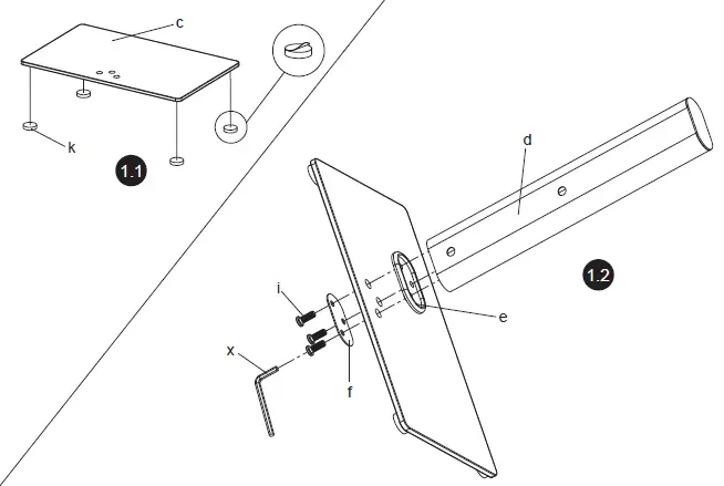
St e p 1
Connecting the Support C St e p 1 olumn to Tempered Glass

St e p 2
Connecting the TV Plate to Support Column
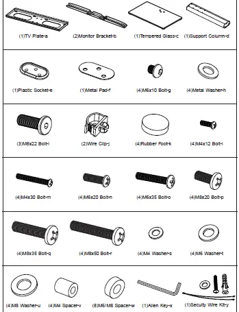
*TV Plate(a) can be installed on wall optionally, wall mounting hardware have not included.
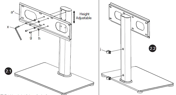
St e p 3
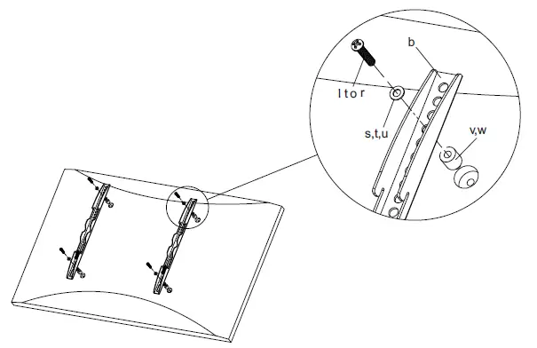
Mounting the Monitor Brackets to a TV
First of all, Once you have determined the correct diameter, please see the diagram as below. You will thread the Bolt into the TV using the correct Washer(s,t,u), and using the
spacer(v,w) if necessary. Please make sure the Monitor Brackets are vertically centered and level with each other. make sure the diameter of the Bolt( l to r ) your TV requires
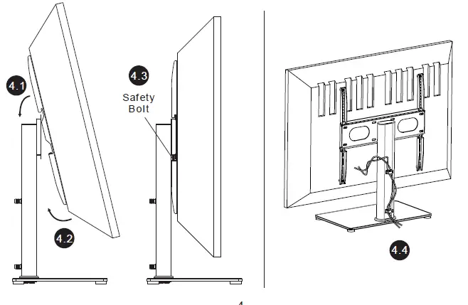
St e p 4
Attaching TV To TV P St e p 4 late and Managing the Wires
St e p 5
Attaching the S St e p 5 ecurity Steel Wire to the TV
If your TV is located nearby the wall as the Diagram 5a, then a steel wire can be attached for added security. Attaching the two ends of steel wire to the top two holes on the back of TV, shown in Diagram 5b
Attaching the another end of steel wire to the wall according to your wall type, shown in Diagram 5c, 5d and 5e.
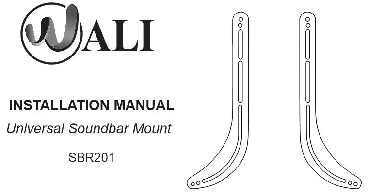
INSTALLATION MANUAL
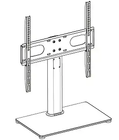
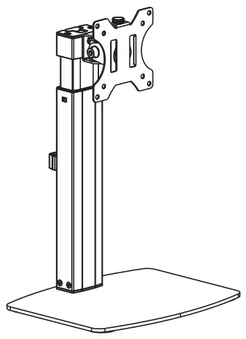
Monitor Desk Stand
GPV001
![]() www.walielectric.com
www.walielectric.com
![]() [email protected]
[email protected]
![]() 1-844-SATTLER (18447288537)
1-844-SATTLER (18447288537)
![]() WARNING
WARNING
If you do not understand these directions, or if you have any doubts about the safety of the installation, please call a qualified technician. Check carefully to make sure there are no missing or defective parts. Improper installation may cause damage or serious injury. Do not use this product for any purpose that is not explicitly specified in this manual. Do not exceed weight capacity. We cannot be liable for damage or injury caused by improper mounting, incorrect assembly, or inappropriate use.
![]() TIPOVER WARNING
TIPOVER WARNING
SERIOUS OR FATAL CRUSHING INJURIES CAN OCCUR FROM TIPOVER. TO HELP PREVENT TIPOVER:
● NEVER ALLOW CHILDREN TO CLIMB, STAND, HANG, OR PLAY ON ANY PART OF THE MONITOR OR STAND.
● USE TIPOVER RESTRAINT OR ANCHOR STAND TO WALL.
THE USE OF TIP-OVER RESTRAINTS MAY ONLY REDUCE, BUT NOT ELIMINATE THE RISK OF TIP-OVER.
SMALL PARTS- NOT FOR CHILDREN UNDER 3 YEARS. ADULT SUPERVISION IS REQUIRED.
Supplied Parts List
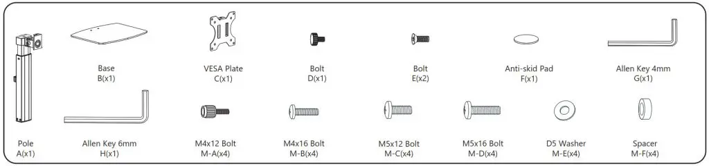
- Connect Pole
Aand BaseBusing BoltEand tighten with Allen Key 4mmG.
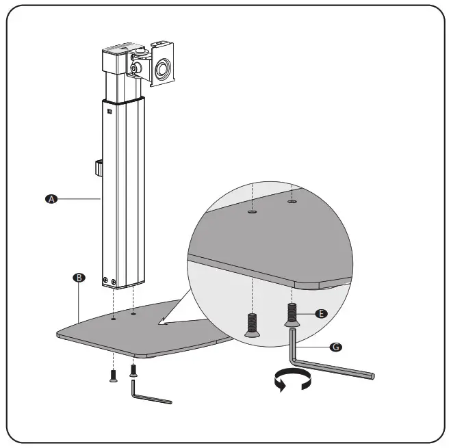
- Tear off the protective paper to attach Anti-Skid Pad
Fto the bottom designated position of BaseBas image shown.

Step 3.1 : Select TV Screws
Only one screw size fits your TV
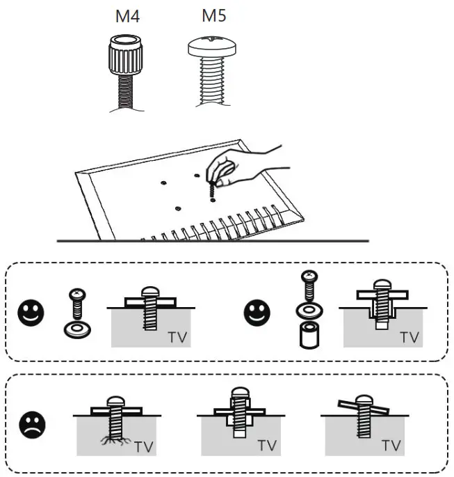 Step 3.2
Select Spacers ( if needed )
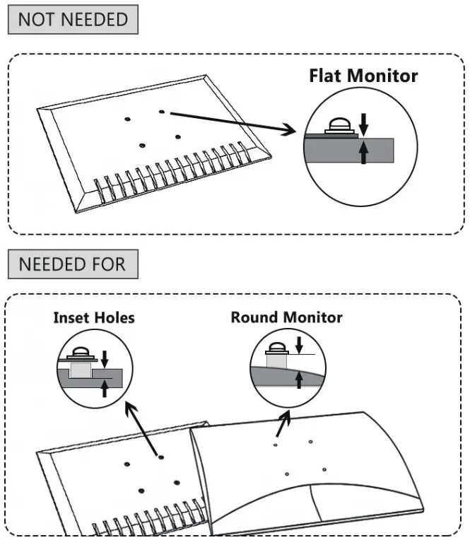 Step 3.3a
Flat Back Monitor
Select M4x12 Bolt M-A or M5x12 Bolt M-C according to your TV/Monitor, connect VESA Plate E together with D5 Washer M-E into the mounting holes on the back of TV/Monitor, tighten with a screwdriver. (Screwdriver not included)
 Step 3.3b
Curved Back Monitor
Select M4x16 Bolt M-B or M5x16 Bolt M-D according to your TV/Monitor, connect VESA Plate E together with D5 Washer M-E and Spacer M-F into the mounting holes on the back of the TV/Monitor, tighten with a screwdriver. (Screwdriver not included)
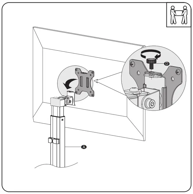
4. Put the assembled TV/ Monitor onto the Pole A and tighten the VESA Plate with Bolt D for stability.
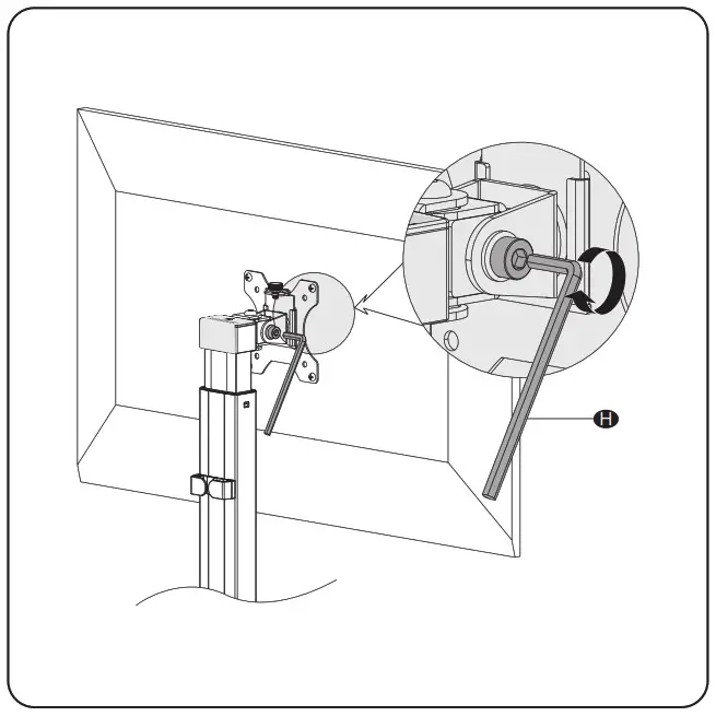
5. Adjust the tilt angle using Allen Key 6mm H .
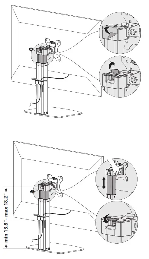
6. Tear off the warning label from the gas spring button. Keep your hand pressing on the top of Pole A to prevent it pops up. Open up the button and adjust the Pole A to the personally preferred height. Lock the button and ensure stability. Suggest standing for easier adjustment.
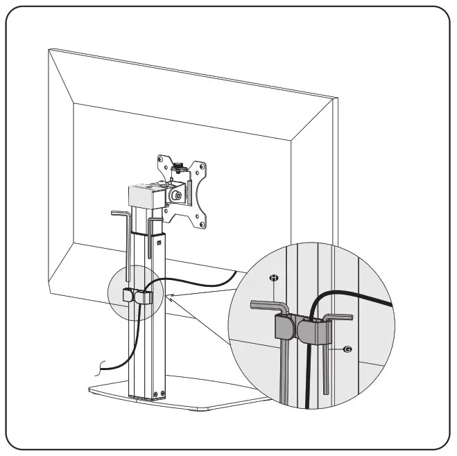
7. Guide the cable through the clip holder and store the Allen Keys G H in the holder.
8. Manually swivel, tilt or rotate the monitor for the best viewing angle.

 www.walielectric.com
[email protected]
1-844-SATTLER (18447288537)
WARNING
If you do not understand these directions, or if you have any doubts about the safety of the installation, please call a qualified technician. Check carefully to make sure there are no missing or defective parts. Improper installation may cause damage or serious injury. Do not use this product for any purpose that is not explicitly specified in this manual. Do not exceed weight capacity. We cannot be liable for damage or injury caused by improper mounting, incorrect assembly or inappropriate use.
TIPOVER WARNING
SERIOUS OR FATAL CRUSHING INJURIES CAN OCCUR FROM TIPOVER. TO HELP PREVENT TIPOVER:
- NEVER ALLOW CHILDREN TO CLIMB, STAND, HANG, OR PLAY ON ANY PART OF MONITOR OR STAND. USE
- TIPOVER RESTRAINT OR ANCHOR STAND TO WALL.
USE OF TIPOVER RESTRAINTS MAY ONLY REDUCE, BUT NOT ELIMINATE RISK OF TIP OVER.
SMALL PARTS- NOT FOR CHILDREN UNDER 3 YEARS. ADULT SUPERVISION IS REQUIRED.
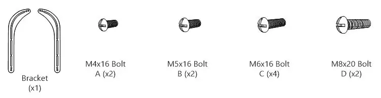
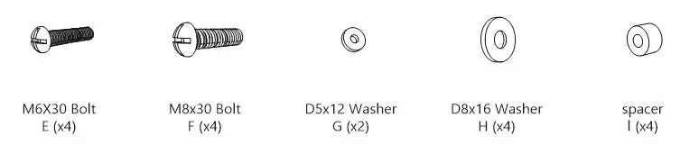
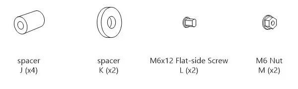
Supplied Parts List
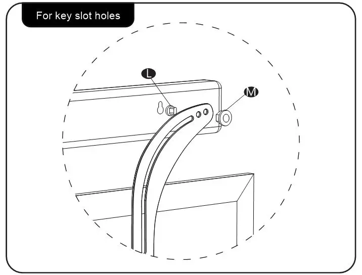
Install With TV/Monitor
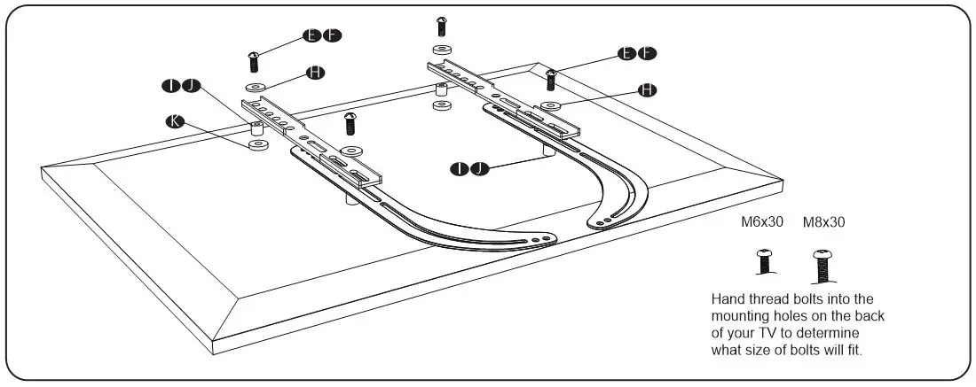
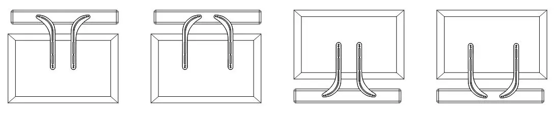
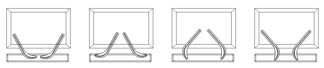
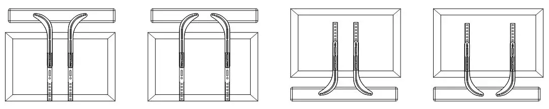
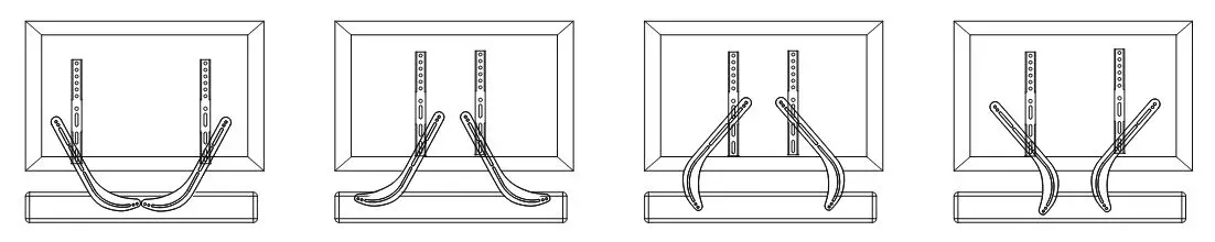
- According to the distances of the TV & Soundbar mounting holes, select the appropriate mounting positions on the Bracket. Rotate or turn over the Bracket for the best mounting solutions.
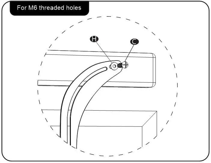
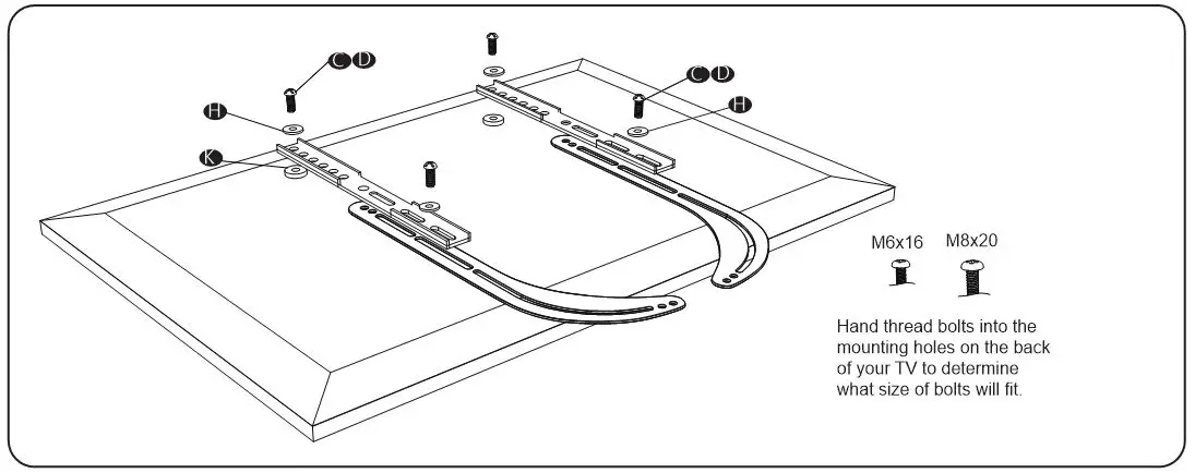
- Select the correct TV mounting bolts
Select M6x16 Bolt C or M8x20 Bolt D according to your TV, connect Bracket together with D8x16 Washer H into the mounting holes on the back of the TV, tighten with a screwdriver. (Screwdriver not included)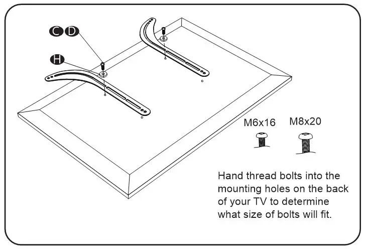
- Select the correct Soundbar mounting bolts
Hand thread bolts into the mounting holes on the back of your Soundbar to determine what size of bolts will fit.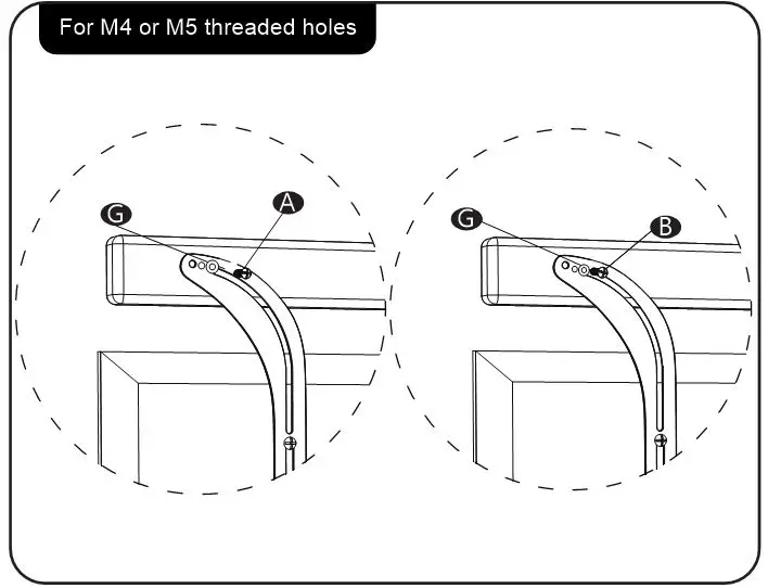
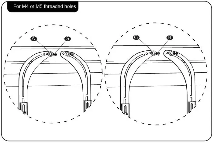
Install With TV Mount
- Assemble Soundbar with the Bracket and VESA brackets from your TV mount to TV. According to the distances of the TV & Soundbar mounting holes, select the appropriate mounting positions on the Bracket. Rotate or turn over the Bracket for the best mounting solutions. The Bracket should be mounted between the TV and the VESA brackets. (VESA bracket not included)

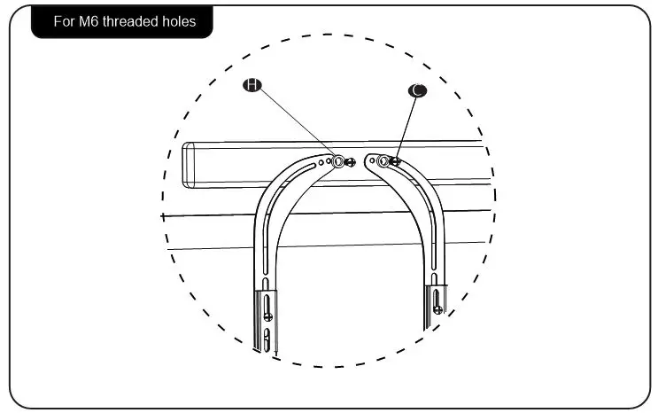
- Select the correct TV mounting bolts
- 2a. Select M6x16 Bolt C or M8x20 Bolt DD according to your TV, connect Bracket together with D8x16 Washer H , VESA Brackets and Spacer KK into the mounting holes on the back of the TV, tighten with a screwdriver. (Screwdriver & VESA bracket not included)
- 2b. Select M6x30 Bolt E or M8x30 Bolt Fj and spacers II or J according to your TV, connect Bracket together with D8x16 Washer H , VEiSA Brackets and Spacer K into the mounting holes on the back of the TV, tighten with a screwdriver. (Screwdriver & VESA bracket not included)
- 2a. Select M6x16 Bolt C or M8x20 Bolt DD according to your TV, connect Bracket together with D8x16 Washer H , VESA Brackets and Spacer KK into the mounting holes on the back of the TV, tighten with a screwdriver. (Screwdriver & VESA bracket not included)
- Select the correct Soundbar mounting bolts
Hand thread bolts into the mounting holes on the back of your Soundbar to determine what size of bolts will fit.