SureCall Cell Phone Signal Booster Home Yagi Antenna
Introduction
Thank you for purchasing SureCall’s Flare 3.0 cellular signal booster kit. SureCall’s Flare 3.0 was specifically designed to eliminate frustrations over dropped calls and limited range by amplifying incoming and outgoing cellular signals in homes and offices. If you have any questions during setup, please reach out to our US-based experienced support technicians:
Call: 1-888-365-6283
Email: [email protected]
Or visit: www.surecall.com/support
How It Works
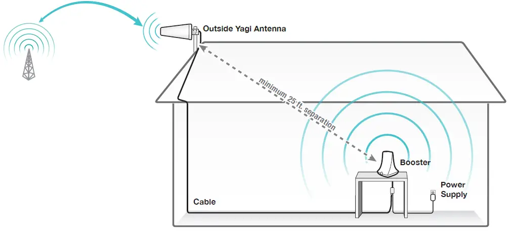
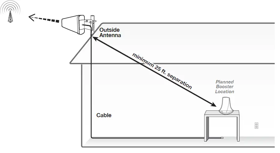
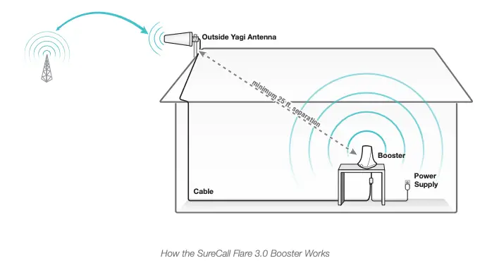
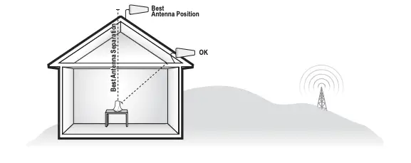
- An outside antenna collects signal from the cell tower.
- The outside antenna sends the signal to the booster through coax cable.
- The booster amplifies the cell signal and rebroadcasts the signal indoors to all mobile devices within range.
- The booster amplifies outgoing cell signal back to the tower.

PACKAGE CONTENTS
Unpack all package contents. For missing or damaged items, contact your reseller. Turn over the signal booster and record the model and serial number for reference:
Serial #: ________________________________________________________________
Purchase Date: __________________________________________________________
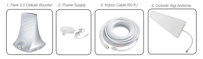
Keep the carton and packing material to store the product in case you need to return. Your Flare 3.0 signal booster package includes the following items:
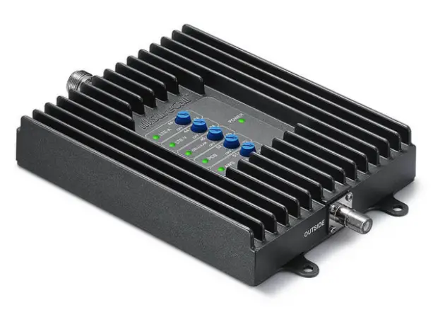
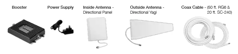
- SureCall Flare 3.0 signal booster
- Power supply
- Cable for connecting the outside antenna to the signal booster
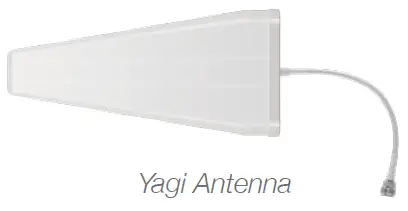
- Outside Yagi antenna

Warning: Unauthorized antennas, cables, and/or coupling devices are prohibited by FCC new rules. Please contact FCC for details: 1-888-CALL-FCC. Changes or mod ifications not expressly approved by SureCall could void the user’s authority to operate the equipment.
Before Installation
- Prior to securing the location of any booster parts, a “soft install” is recommended as adjustments may be needed to optimize performance.
- Note that the outside antenna can be mounted to an exterior surface or a 1-2” diameter pole. A mounting pole is available separately (SC-MOUNT-JBAR) . PVC piping from your local hardware can also be used.
- Your planned location for the booster (central to where signal is needed) should be near an existing electrical outlet.
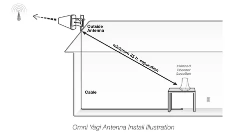
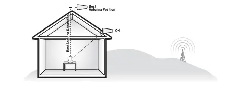
- Ensure adequate separation between the planned locations of the booster and outside antenna (at least 25 ft.).
- Ensure sufficient cable length between the outside antenna location and booster location. The length of the provided cable is 50 ft.
Installation Overview
Step 1. Find the outside area with the strongest signal.
Step 2. Install the outside antenna
Step 3. Place the Flare 3.0 on a table or desktop, center of the area where signal is needed.
Step 4. Connect the booster to an AC power source.
Step 1. Find the Area With the Strongest Signal
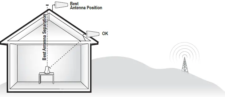
Using your phone, identify the outside location with the strongest signal for placement of your outside antenna. Generally, this is found above the roofline on the side facing your nearest cell tower and as high as possible – where the antenna can ‘see’ your cell tower. To find the location of your carrier’s closest cell tower, go to www.antennasearch.com.
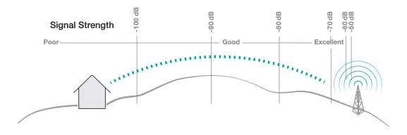
The coverage area that the booster provides is directly related to the strength of incoming signal received by the outdoor antenna. Mounting the outside antenna where the signal is the strongest will provide the best results. Please note, if signal is extremely weak where the outside antenna is installed, indoor coverage will be limited. Note that Bars are not always a reliable measure of signal. The best way to confirm signal coverage is t he ability to place and hold a call.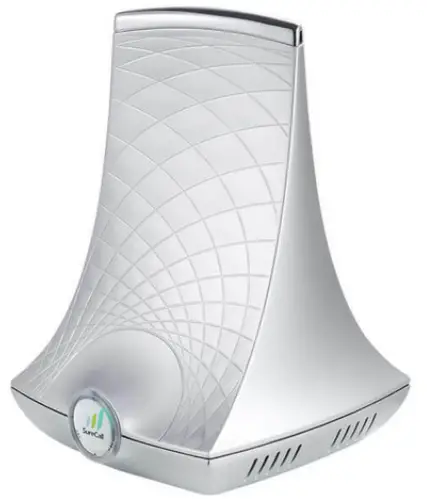
Putting your phone in Field Test mode will also indicate what level of decibels (dB) your phone is currently receiving. Decibels are measured in the negatives, and a score closer to zero indicates you have a better signal. A signal of -120 dB indicates you have no service, while a score of about -50 dB means you have excellent signal strength For specific dB signal measurements, use the methods below.
- Apple iPhones: Dial *3001#12345#* and press Call. In the top-left corner, a dB number appears instead of bars.
- Android devices: download the app “Network Signal Info” in the Google Play store
Step 2. Install the Outside Antenna
After identifying the area of strongest signal, choose the surface where you will mount the outside antenna. Using the provided hardware, mount the outside antenna at the highest possible elevation, allowing a minimum separation of 25 feet from the planned location of the booster.
Once the outside antenna is secured, connect one end of the provided cable to the outside antenna and tighten the connection. Do not collocate antennas or operate the outdoor antenna with any other antenna or signal booster.
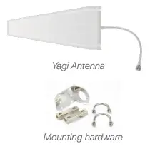
Outside Yagi Antenna Installation Before installing a Yagi, or directional antenna, note that the antenna should be mounted on a pole or pipe (not provided), at the highest possible location and mounted horizontally, aimed in the direction of your nearest cell tower. To find the location of your carrier’s closest cell tower, go to www.antennasearch.com.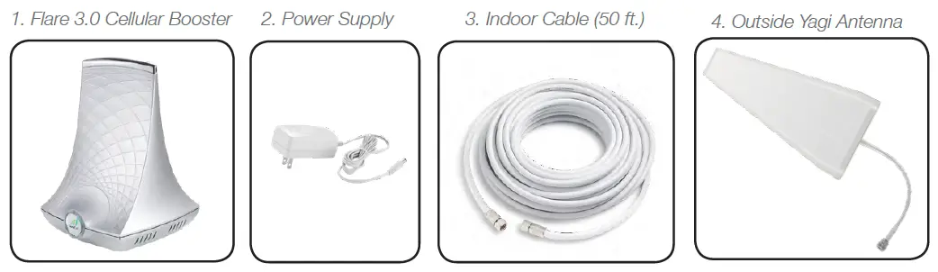
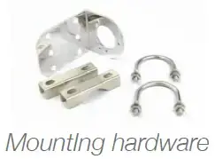
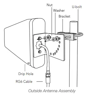
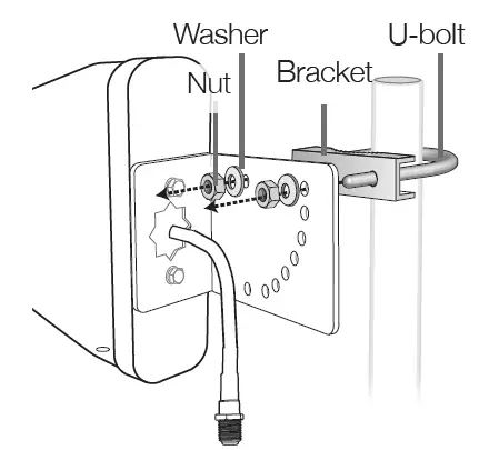
Ensure that the mounting area has at least a 12-inch radius clear of obstructions and other radiating elements and orient the antenna with the drip hole at the bottom. Once you have identified your install location, assemble the u-bolt,
bracket, nuts and washers onto a pole or pipe (not provided) as shown in the illustration. Keep the connections loose enough to allow the antenna to rotate until the optimum direction is found. Once the outside antenna is secured to a pipe or pole, connect antenna to one end of the provided RG6 cable and tighten the connection. Run the cable along route to planned location of your booster.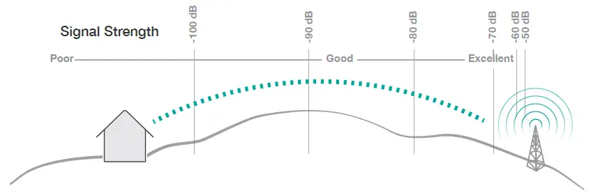
Note: This booster is rated for 5-15V input voltage. DO NOT use the booster with a higher voltage power supply. This can damage the booster, cause personal injury, and void your warranty.
This booster should not be used near open fir e or flame. Storage and transportation: Store and place in non-extreme room-temperature and dry environment.
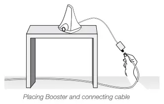
Step 3. Place the Booster
Place the booster in a central location where signal is needed and at least 25 ft. from the outdoor antenna location. When placing the booster, note that further separation between the booster and outside antenna will increase booster performance. Connect the open end of the RG6 cable from the outside antenna to the booster and tighten connection. Please note that the performance and range of your booster depends on three factors:
- Signal strength at the location of the outside antenna.
- Interior building materials between the booster and your mobile device.
- Distance between the outside antenna and booster (while at least 25 ft. separation is recommended, further separation will increase performance).
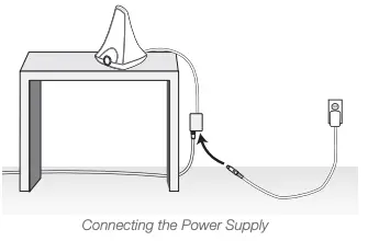
Step 4: Connect to Power
Once the booster and outside antenna are connected and in place, connect the power cord to the signal booster and plug into a power outlet.
Enjoy Boosted Signal
Place a call in the room where the booster is located to confirm that your phone is receiving a boosted signal. Remember: Bars are not always a reliable measure of signal. The best way to confirm signal coverage is the ability to place and hold a call.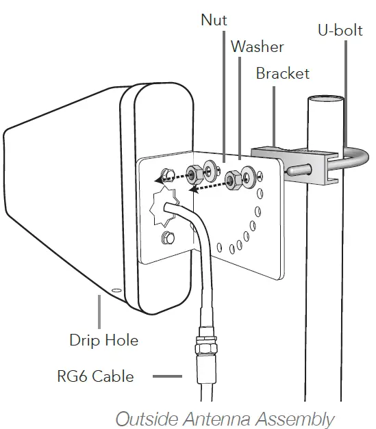
LED Indicators
IF YOU WANT TO IMPROVE PERFORMANCE
- Identify a location outside that receives a stronger signal and move the outside antenna to that location (higher is usually better).
- Increase the distance between the booster and outside antenna.
- See more tips and tricks or contact us at www.SureCall.com/support
TROUBLESHOOTING
If you have any questions during setup, please reach out to our US-based experienced support technicians:
Call: 1-888-365-6283, Email: [email protected], or Visit: www.surecall.com/support
Problem Resolution
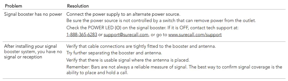
Signal booster has no power Connect the power supply to an alternate power source. Be sure the power source is not controlled by a switch that can remove power from the outlet. Check the POWER LED ( ) on the signal booster. If it is OFF, contact tech support at: 1-888-365-6283 or [email protected], or go to www.surecall.com/support
After installing your signal booster system, you have no signal or reception Verify that cable connections are tightly fitted to the booster and antenna. Try further separating the booster and antenna. Verify that there is usable signal where the antenna is placed. Remember: Bars are not always a reliable measure of signal. The best way to confirm signal coverage is t he ability to place and hold a call.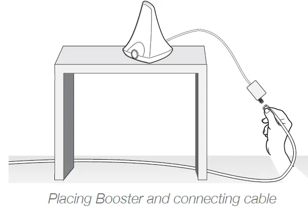
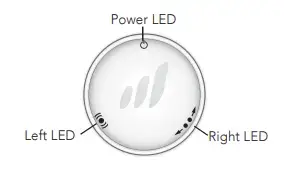
NOTE: Normal operation is indicated by LEDs that are OFF -or- YELLOW Flashing. Only the presence of RED LEDs indicate potential need for adjustments.
Note that power cycling the booster after each adjustment may be necessary.
LED
Position Condition Indication
Left or Right
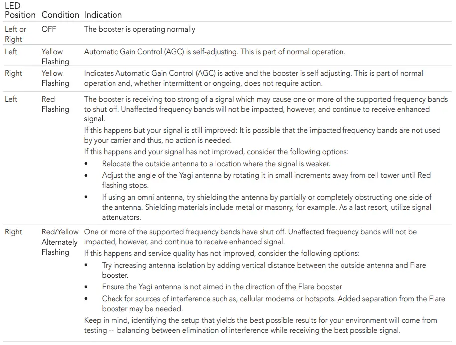
OFF The booster is operating normally
Left Yellow
Flashing
Automatic Gain Control (AGC) is self-adjusting. This is part of normal operation.
Right Yellow
Flashing
Indicates Automatic Gain Control (AGC) is active and the booster is self adjusting. This is part of normal
operation and, whether intermittent or ongoing, does not require action.
Left Red Flashing
The booster is receiving too strong of a signal which may cause one or more of the supported frequency bands to shut off. Unaffected frequency bands will not be impacted, however, and continue to receive enhanced signal.
If this happens but your signal is still improved: It is possible that the impacted frequency bands are not used
by your carrier and thus, no action is needed. If this happens and your signal has not improved, consider the following options:
- Relocate the outside antenna to a location where the signal is weaker.
- Adjust the angle of the Yagi antenna by rotating it in small increments away from cell tower until Red flashing stops.
- If using an omni antenna, try shielding the antenna by partially or completely obstructing one side of the antenna. Shielding materials include metal or masonry, for example. As a last resort, utilize signal attenuators.
Right Red/Yellow Alternately Flashing
One or more of the supported frequency bands have shut off. Unaffected frequency bands will not be impacted, however, and continue to receive enhanced signal.
If this happens and service quality has not improved, consider the following options:
- Try increasing antenna isolation by adding vertical distance between the outside antenna and Flare booster.
- Ensure the Yagi antenna is not aimed in the direction of the Flare booster.
- Check for sources of interference such as, cellular modems or hotspots. Added separation from the Flare booster may be needed.
Keep in mind, identifying the setup that yields the best possible results for your environment will come from testing — balancing between elimination of interference while receiving the best possible signal.
Specifications
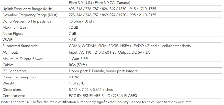
| Flare 3.0 (U.S.) ; Flare 3.0 CA (Canada) | |
| Uplink Frequency Range (MHz): | 698–716 / 776–787 / 824–849 / 1850–1915 / 1710–1755 |
| Downlink Frequency Range (MHz): | 728–746 / 746–757 / 869–894 / 1930–1995 / 2110–2155 |
| Donor/Server Port Impedance: | 75 ohm / 50 ohm |
| Maximum Gain: | 72 dB |
| Noise Figure: | 7 dB |
| VSWR: | ≤2.0 |
| Supported Standards: | CDMA, WCDMA, GSM, EDGE, HSPA+, EVDO 4G and all cellular standards |
| AC Input: | Input: AC 110 – 240 V, 60 Hz ; Output: DC 5V / 3A |
| Maximum Output Power: | 1 Watt EIRP |
| Cable: | RG6 (50 ft.) |
| RF Connectors: | Donor port: F Female, Server port: Integral |
| Power Consumption: | <12W |
| Weight: | 1. 8125 lb. |
| Dimensions: | 5.125 × 7.25 × 5.625 inches |
| Certifications: | FCC ID: RSNFLARE-3 ; IC : 7784A-FLARE3 |
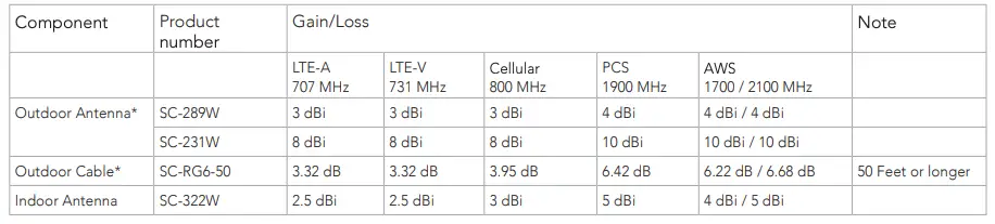
Kitting Information
| Component | Product number | Gain/Loss | Note | ||||
| LTE-A 707 MHz | LTE-V 731 MHz | Cellular 800 MHz | PCS
1900 MHz |
AWS
1700 / 2100 MHz |
|||
| Outdoor Antenna* | SC-289W | 3 dBi | 3 dBi | 3 dBi | 4 dBi | 4 dBi / 4 dBi | |
| SC-231W | 8 dBi | 8 dBi | 8 dBi | 10 dBi | 10 dBi / 10 dBi | ||
| Outdoor Cable* | SC-RG6-50 | 3.32 dB | 3.32 dB | 3.95 dB | 6.42 dB | 6.22 dB / 6.68 dB | 50 Feet or longer |
| Indoor Antenna | SC-322W | 2.5 dBi | 2.5 dBi | 3 dBi | 5 dBi | 4 dBi / 5 dBi | |
| PreAGC | PreAGC | |||||
| Pulse GSM | 4.1 MHz AWGN | |||||
| Frequency (MHz) | Input (dBm) | Output (dBm) | Gain (dB) | Input (dBm) | Output (dBm) | Gain (dB) |
| Uplink: 1710-1755 | -49.5 | 20.0 | 69.5 | -49.0 | 19.4 | 68.4 |
| Uplink: 1850-1915 | -49.5 | 22.1 | 71.6 | -45.8 | 21.6 | 67.4 |
| Uplink: 824-849 | -39.3 | 25.3 | 64.5 | -36.6 | 26.0 | 62.6 |
| Uplink: 698-716 | -36.8 | 25.0 | 61.8 | -37.1 | 25.2 | 62.3 |
| Uplink: 777-787 | -38.6 | 22.1 | 60.7 | -38.4 | 20.5 | 58.9 |
| Downlink: 2110-2155 | -55.2 | 12.5 | 67.7 | -57.0 | 10.4 | 67.4 |
| Downlink: 1930-1995 | -57.2 | 11.2 | 68.4 | -60.4 | 8.2 | 68.6 |
| Downlink: 869-894 | -51.2 | 11.8 | 63.0 | -50.8 | 10.9 | 61.7 |
| Downlink: 728-746 | -47.5 | 14.5 | 62.0 | -50.7 | 10.7 | 61.4 |
| Downlink: 746-757 | -45.8 | 11.8 | 57.6 | -49.4 | 8.5 | 57.9 |
CONSUMER GUIDELINES
This is a CONSUMER device
BEFORE USE, you MUST REGISTER THIS DEVICE with your wireless provider and have your provider’s consent. Most wireless providers consent to the use of signal boosters. Some providers may not consent to the use of this device on their network. If you are unsure, contact your provider. In Canada, BEFORE USE you must meet all requirements set out in ISED CPC-2-1-051 You MUST operate this device with approved antennas and cables as specified by the manufacturer. Antennas MUST be installed at least 20 cm (8 inches) from (i.e. MUST NOT be installed within 20 cm of) any person. You MUST cease operation of this device immediately if requested by the FCC (or ISED in Canada) or a licensed wireless service provider.
WARNING: E911 location information may not be provided or may be inaccurate for calls served by using this device.
This device may be operated ONLY in a fixed location, for in-building use.
Register your cellular booster with your wireless carrier at the following :
Verizon: http://www.verizonwireless.com/wcms/consumer/register-signal-booster.html
AT&T: https://securec45.securewebsession.com/attsignalbooster.com
T-Mobile: https://support.t-mobile.com/docs/DOC-9827
Sprint: https://www.sprint.com/legal/fcc_boosters.html
U.S. Cellular: http://www.uscellular.com/uscellular/support/fcc-booster-registration.jsp
This device complies with Part 15 of FCC Rules. Operation is subject to the following two conditions:
- this device may not cause harmful interference, and
- this device must accept any interference received, including interference that may cause undesired operation.
CAN ICES-3 (B)/NMB-3(B) (Canada) :
This Class B digital apparatus meets all requirements of the Canadian Interference Causing Equipment Regulations. Operation is subject to the following two conditions:
- this device may not cause harmful interference, and
- this device must accept any interference received, including interference that may cause undesired operation
The Manufacturer’s rated output power of this equipment is for single carrier operation. For situations when multiple carrier signals are present, the rating would have to be reduced by 3.5 dB, especially where the output signal is re-radiated and can cause interference to adjacent band users. This power reduction is to be by means of input power or gain reduction and not by an attenuator at the output of the device.
WARRANTY
Three-Year Product Warranty
Activate your three-year manufacturer’s warranty at www.SureCall.com/activate
SureCall warrants its products for three years from the date of purchase against defects in workmanship and/or materials. Specifications are subject to change. The three-year warranty only applies to products meeting the latest FCC Certification Guidelines stated on 2/20/2013 and going into effect April 30, 2014. A two-year warranty applies to any products manufactured before May 1, 2014. Products returned by customers must be in their original, un-modified condition, shipped in the original or protective packaging with proof-of-purchase documentation enclosed, and a Return Merchandise Authorization (RMA) number printed clearly on the outside of the shipping container.
Buyers may obtain an RMA number for warranty returns by calling the SureCall Return Department toll-free at 1-888-365-6283. Any returns received by SureCall without an RMA number clearly printed on the outside of the shipping container will be returned to sender. In order to receive full credit for signal boosters, all accessories originally included in the signal booster box must be returned with the signal booster. (The Buyer does not need to include accessories sold in addition to the signal booster, such as antennas or cables.)
This warranty does not apply to any product determined by SureCall to have been subjected to misuse, abuse, neglect, or mishandling that alters or damages the product’s physical or electronic properties. SureCall warrants to the Buyer that each of its products, when shipped, will be free from defects in material and workmanship, and will perform in full accordance with applicable specifications. The limit of liability under this warranty is, at SureCall’s option, to repair or replace any product or part thereof which was purchased up to THREE YEARS after May 1, 2014 or TWO YEARS for products purchased before May 1, 2014, as determined by examination by SureCall, prove defective
in material and/or workmanship. Warranty returns must first be authorized in writing by SureCall. Disassembly of any SureCall product by anyone other than an authorized representative of SureCall voids this warranty in its entirety. SureCall reserves the right to make changes in any of its products without incurring any obligation to make the same changes on previously delivered products.
As a condition to the warranties provided for herein, the Buyer will prepay the shipping charges for all products returned to SureCall for repair, and SureCall will pay the return shipping with the exception of products returned from outside the United States, in which case the Buyer will pay the shipping charges.
The Buyer will pay the cost of inspecting and testing any goods returned under the warranty or otherwise, which are found to meet the applicable specifications or which are not defective or not covered by this warranty.
Products sold by SureCall shall not be considered defective or non-conforming to the Buyer’s order if they satisfactorily fulfill the performance requirements that were published in the product specification literature, or in accordance with samples provided by SureCall. This warranty shall not apply to any products or parts thereof which have been subject to accident, negligence, alteration, abuse, or misuse. SureCall makes no warranty whatsoever in respect to accessories or parts not supplied by it.
Limitations of Warranty, Damages and Liability
EXCEPT AS EXPRESSLY SET FORTH HEREIN, THERE ARE NO WARRANTIES, CONDITIONS, GUARANTEES, OR REPRESENTATIONS AS TO MERCHANTABILITY, FITNESS FOR A PARTICULAR PURPOSE, OR OTHER WARRANTIES, CONDITIONS, GUARANTEES, OR REPRESENTATIONS, WHETHER EXPRESSED OR IMPLIED, IN LAW OR IN FACT, ORAL OR IN WRITING. SURECALL AGGREGATE LIABILITY IN DAMAGES OR OTHERWISE SHALL NOT EXCEED THE PAYMENT, IF ANY, RECEIVED BY CELLPHONE-MATE, INC. FOR THE UNIT OF PRODUCT OR SERVICE FURNISHED OR TO BE FURNISHED, AS THE CASE MAY BE, WHICH IS THE SUBJECT OF CLAIM OR DISPUTE. IN NO EVENT SHALL SURECALL BE LIABLE FOR INCIDENTAL, CONSEQUENTIAL, OR SPECIAL DAMAGES, HOWSOEVER CAUSED.
All matters regarding this warranty shall be interpreted in accordance with the laws of the State of California, and any controversy that cannot be settled directly shall be settled by arbitration in California in accordance with the rules then prevailing of the American Arbitration Association, and judgment upon the award rendered may be entered in any court having jurisdiction thereof. If one or more provisions provided herein are held to be invalid or unenforceable under applicable law, then such provision shall be ineffective and excluded to the extent of such invalidity or unenforceability without affecting in any way the remaining provisions hereof.
SureCall has made a good faith effort to ensure the accuracy of the information in this document and disclaims the implied warranties of merchantability and fitness for a particular purpose and makes no express warranties, except as may be stated in its written agreement with and for its customers. SureCall shall not be held liable to anyone for any indirect, special or consequential damages due to omissions or errors. The information and specifications in this document are subject to change without notice. © 2020. All Rights Reserved. All trademarks and registered trademarks are the property of their respective owners.
![]()
Cellular signal booster kit with combined booster and indoor antenna
04.02.2020
Introduction
Thank you for purchasing SureCall’s Flare 3.0 cellular signal booster kit. SureCall’s Flare 3.0 was specifically designed to eliminate frustrations over dropped calls and limited range by amplifying incoming and outgoing cellular signals in homes and offices.
If you have any questions during setup, please reach out to our US-based experienced support technicians:
Call: 1-888-365-6283
Email: [email protected]
Or, visit: www.surecall.com/support
![]() Watch installation, optimization and troubleshooting techniques
Watch installation, optimization and troubleshooting techniques

 Stay up to date with all things SureCall
How It Works
- An outside antenna collects signal from the cell tower.
- The outside antenna sends the signal to the booster through coax cable.
- The booster amplifies the cell signal and rebroadcasts the signal indoors to all mobile devices within range.
- The booster amplifies outgoing cell signal back to the tower.

Package Contents
Unpack all package contents. For missing or damaged items, contact your reseller.
Turn over the signal booster and record the model and serial number for reference:
Serial #: ________________________________________________________________
Purchase Date: __________________________________________________________
Keep the carton and packing material to store the product in case you need to return. Your Flare 3.0 signal booster package includes the following items:
- SureCall Flare 3.0 signal booster
- Power supply
- Cable for connecting the outside antenna to the signal booster
- Outside Yagi antenna
Warning: Unauthorized antennas, cables, and/or coupling devices are prohibited by FCC new rules. Please contact FCC for details: 1-888-CALL-FCC. Changes or modifications not expressly approved by SureCall could void the user’s authority to operate the equipment.
Before Installation
- Prior to securing the location of any booster parts, a “soft install” is recommended as adjustments may be needed to optimize performance.
- Note that the outside antenna can be mounted to an exterior surface or a 1-2” diameter pole. A mounting pole is available separately (SC-J-Mount) . PVC piping from your local hardware can also be used.
- Your planned location for the booster (central to where signal is needed) should be near an existing electrical outlet.
- Ensure adequate separation between the planned locations of the booster and outside antenna (at least 25 ft.).
- Ensure sufficient cable length between the outside antenna location and booster location. The length of the provided cable is 50 ft.
Installation
Installation Overview
Step 1. Find the outside area with the strongest signal.
Step 2. Install the outside antenna
Step 3. Place the Flare 3.0 on a table or desktop, center of the area where signal is needed.
Step 4. Connect the booster to an AC power source.
Installation
Step 1. Find the Area With the Strongest Signal
Using your phone, identify the outside location with the strongest signal for placement of your outside antenna. Generally, this is found above the roofline on the side facing your nearest cell tower and as high as possible – where the antenna can ‘see’ your cell tower. To find the location of your carrier’s closest cell tower, go to www.antennasearch.com.
The coverage area that the booster provides is directly related to the strength of incoming signal received by the outdoor antenna. Mounting the outside antenna where the signal is the strongest will provide the best results. Please note, if signal is extremely weak where the outside antenna is installed, indoor coverage will be limited.
Note that Bars are not always a reliable measure of signal. The best way to confirm signal coverage is the ability to place and hold a call.
Step 2. Install the Outside Antenna
After identifying the area of strongest signal, choose the surface where you will mount the outside antenna.
 Using the provided hardware, mount the outside antenna at the highest possible elevation, allowing a minimum separation of 25 feet from the planned location of the booster.
Once the outside antenna is secured, connect one end of the provided cable to the outside antenna and tighten the connection.
Do not collocate antennas or operate the outdoor antenna with any other antenna or signal booster.
Outside Yagi Antenna Installation
Before installing a Yagi, or directional antenna, note that the antenna should be mounted on a pole or pipe (not provided), at the highest possible location and mounted horizontally, aimed in the direction of your nearest cell tower. To find the location of your carrier’s closest cell tower, go to www.antennasearch.com.
 Ensure that the mounting area has at least a 12-inch radius clear of obstructions and other radiating elements and orient the antenna with the drip hole at the bottom.
Once you have identified your install location, assemble the u-bolt, bracket, nuts and washers onto a pole or pipe (not provided) as shown in the illustration. Keep the connections loose enough to allow the antenna to rotate until the optimum direction is found.
Once the outside antenna is secured to a pipe or pole, connect antenna to one end of the provided RG6 cable and tighten the connection. Run the cable along route to planned location of your booster.
Note: This booster is rated for 5-15V input voltage. DO NOT use the booster with a higher voltage power supply. This can damage the booster, cause personal injury, and void your warranty.
This booster should not be used near open fire or flame. Storage and transportation: Store and place in non-extreme room-temperature and dry environment.
Step 3. Place the Booster
 Place the booster in a central location where signal is needed and at least 25 ft. from the outdoor antenna location. When placing the booster, note that further separation between the booster and outside antenna will increase booster performance. Connect the open end of the RG6 cable from the outside antenna to the booster and tighten connection. Please note that the performance and range of your booster depends on three factors:
- Signal strength at the location of the outside antenna.
- Interior building materials between the booster and your mobile device.
- Distance between the outside antenna and booster (while at least 25 ft. separation is recommended, further separation will increase performance).
Step 4: Connect to Power
 Once the booster and outside antenna are connected and in place, connect the power cord to the signal booster and plug into a power outlet.
Enjoy Boosted Signal
Place a call in the room where the booster is located to confirm that your phone is receiving a boosted signal. Remember: Bars are not always a reliable measure of signal. The best way to confirm signal coverage is the ability to place and hold a call.
FCC 27.5 (d)(4): Fixed, mobile, and portable (hand-held) stations operating in the 1710-1755 MHz band as well as mobile and portable stations operating in the 1695- 1710 MHz and 1755-1780 MHz bands are limited to 1 watt EIRP.
Fixed stations operating in the 1710-1755 MHz band are limited to a maximum antenna height of 10 meters above ground.
IF YOU WANT TO IMPROVE PERFORMANCE
- Identify a location outside that receives a stronger signal and move the outside antenna to that location (higher is usually better).
- Increase the distance between the booster and outside antenna.
- See more tips and tricks or contact us at www.SureCall.com/support
Troubleshooting
If you have any questions during setup, please reach out to our US-based experienced support technicians: Call: 1-888-365-6283, Email: [email protected], or Visit: www.surecall.com/support
Booster LED Diagram
LED Indicators
NOTE: Normal operation is indicated by LEDs that are OFF -or- YELLOW Flashing. Only the presence of RED LEDs indicate potential need for adjustments.
Note that power cycling the booster after each adjustment may be necessary.
Specifications
Kitting Information
*Note: The Flare 3.0 booster is suitable for use with all equivalent and lower gain antennas, as well as, equivalent or greater lengths of cable.
Kitting
Consumer Guidelines
This is a CONSUMER device
BEFORE USE, you MUST REGISTER THIS DEVICE with your wireless provider and have your provider’s consent. Most wireless providers consent to the use of signal boosters. Some providers may not consent to the use of this device on their network. If you are unsure, contact your provider.
In Canada, BEFORE USE you must meet all requirements set out in ISED CPC-2-1-051
You MUST operate this device with approved antennas and cables as specified by the manufacturer. Antennas MUST be installed at least 20 cm (8 inches) from (i.e. MUST NOT be installed within 20 cm of) any person.
You MUST cease operation of this device immediately if requested by the FCC (or ISED in Canada) or a licensed wireless service provider.
WARNING: E911 location information may not be provided or may be inaccurate for calls served by using this device.
This device may be operated ONLY in a fixed location, for in-building use.
Register your cellular booster with your wireless carrier at the following urls:
Verizon: http://www.verizonwireless.com/wcms/consumer/register-signal-booster.html
AT&T: https://securec45.securewebsession.com/attsignalbooster.com/
T-Mobile: https://support.t-mobile.com/docs/DOC-9827
Sprint: https://www.sprint.com/legal/fcc_boosters.html
U.S. Cellular: http://www.uscellular.com/uscellular/support/fcc-booster-registration.jsp
This device complies with Part 15 of FCC Rules. Operation is subject to the following two conditions: (1) this device may not cause harmful interference, and (2) this device must accept any interference received, including interference that may cause undesired operation.
CAN ICES-3 (B)/NMB-3(B) (Canada) :
This Class B digital apparatus meets all requirements of the Canadian Interference Causing Equipment Regulations. Operation is subject to the following two conditions: (1) this device may not cause harmful interference, and (2) this device must accept any interference received, including interference that may cause undesired operation
The Manufacturer’s rated output power of this equipment is for single carrier operation. For situations when multiple carrier signals are present, the rating would have to be reduced by 3.5 dB, especially where the output signal is re-radiated and can cause interference to adjacent band users. This power reduction is to be by means of input power or gain reduction and not by an attenuator at the output of the device.
1 For details on the requirements specified in ISED CPC-2-1-05, visit: http://www.ic.gc.ca/eic/site/smt-gst.nsf/eng/sf08942.html
SureCall, Inc
48346 Milmont Drive
Fremont, California 94538, USA
888.365.6283 | www.surecall.com
Contents
1. FIND AREA OUTSIDE WITH STRONGEST SIGNAL
Using your phone, identify the outside location with the strongest signal. Generally, this is found on the side facing your nearest cell tower and as high as possible.
Note that Bars are not always a reliable measure of signal. The best way to confirm signal coverage is the ability to place and hold a call. For specific dB signal measurements, use the methods below. Note that dB measurements appear as a negative number where the closer to 0, the stronger the signal (eg. -100 dB would be considered a weak signal while -65 dB a strong signal). Apple iPhones: Dial *3001#12345#* and press Call. In the top-left corner, a dB number appears instead of bars. Android devices: download the app “Network Signal Info” in the Google Play store. This signal booster requires a minimum cellular signal reading of -100dB at the location of the outside antenna. Signal between -70dB and -90dB is recommended for best performance. Please note: Signal stronger than -50dB may cause the affected frequency bands to turn off.
2. INSTALL THE OUTSIDE ANTENNA
Outside Antenna Assembly
(not included) at the highest possible elevation. The directional Yagi antenna works best when facing the direction of your carrier’s cellular tower. To find the location of your carrier’s
closest cell tower go to www.cellreception.com. To install the outside antenna, assemble the u-bolt, bracket, nuts and washers as shown in the illustration. Keep the connections loose enough to allow the antenna to rotate until the optimum direction is found. Note: The outside antenna may be installed on a variety of pipe angles. Ensure that the mounting area has at least a 12-inch radius clear of obstructions and other radiating elements and orient the antenna vertically with the drip hole at the bottom. Once the outside antenna is secured to a pipe or pole, connect one end of the provided 50 ft. coax cable to the antenna and tighten the connection.
3. INSTALL THE SIGNAL BOOSTER AND INSIDE ANTENNA
Choose a location for mounting the directional panel antenna on vertical surface. The antenna should be at the approximate height of your cell phone when in use and facing a central area where signal is needed. Please note: Be sure to provide enough separation from outside antenna – at least 25 ft. Also, the outside and inside antennas should face away from one another. Using the plate, mark position of desired screw placement and screw mounting plate into place with the slide panel protruding towards you (see panel antenna illustration below). Slide antenna securely onto mounting plate.
To install the booster, select a location that is near the inside panel antenna and a working AC outlet*. Use the supplied screws or appropriate screws for surface of mounting location and drill through screw tab holes on booster (see Booster Components Diagram illustration) and mount the booster to a wall. Connect the inside antenna and booster by connecting one end of the provided 20 ft. of coax cable to the inside antenna and
the other end of the cable to the booster port marked “INSIDE” and hand-tighten the connection. Next, connect the outside antenna and booster by connecting the remaining end of the 50 ft. cable leading from the outside antenna to the port of the booster marked “OUTSIDE”.
4. CONNECT POWER
Connect the AC power cord to the booster and plug into a 110V AC power outlet. Once the booster has been completely assembled, turn the booster’s power switch on.
Note: If the Power LED does not turn ON or the Alert LEDs continue to flash, see the Troubleshooting section. This booster is rated for 5-15V input voltage. DO NOT use the booster with a higher voltage power supply. This can damage the booster, cause personal injury and void your warranty
CONFIGURE GAIN SETTINGS
The SureCall gain dials should always be at maximum level unless the control light in a specific band is flashing red or flashing red-yellow. In either of these cases, the first action should be to increase the antenna isolation between the inside and outside antenna as much as possible and restart the booster. If the situation continues, you can lower the gain with an attenuator or, as the last resort, reduce the booster gain by 5dB at a time until the control light in the frequency band flashes yellow.
Quick Install Guide
Download the complete manual at www.SureCall.com
Booster Components Diagram
Install Overview
LED Indicators
| LED | LED | |
| Color | Condition | Indication |
| Yellow | Solid | Indicates that the band is Inactive. After a period of time, if there’s no activity the band will go into sleep mode. Light is off while band is active. This is part of normal operation. |
| Yellow | Flashing | Flashing Indicates that the Automatic Gain Control (AGC) is self-adjusting. This is part of normal operation |
| Red | Flashing | Indicates that the booster is receiving too much signal which could cause the affected band to automatically turn off. When this happens:
|
| Yellow/ | Alternately | Oscillation is detected. |
| Red | Flashing | First, try increasing the separation between the inside and outside antennas. If your booster kit uses two directional antennas (example: outside Yagi antenna and inside panel antenna), ensure that they are facing away from one another. If oscillation continues, lower the dB gain in small increments until the light turns off or flashes yellow |
| Red | Solid | Band is off. If a red light has been flashing for an extended time, the band will automatically shut off and display a solid red light. This can also happen when the booster attenuation has been turned all the way down. |
WARNING: Do not attenuate the uplink and downlink dB settings below 35dB. This could cause the affected frequency band to turn off.
If you Want to Improve Coverage
- Find a location that receives a stronger signal and relocate the outside antenna to that location.
- Optimize the Yagi antenna angle.
- Increase the distance between the outside and inside antenna.
- Set each dial on the booster to maximum gain.
Troubleshooting
| Problem | Resolution |
| Signal booster has no power | Connect the power supply to an alternate power source. Verify that the power source is not controlled by a switch that has removed power from the outlet. If the POWER LED on the signal booster is OFF, contact tech support at: 1-888-365- 6283 or [email protected] |
| After completing installation, indoor signal coverage has not improved |
(1) Verify that all cable connections are tightly fitted. (2) Try further separating the booster and antenna. (3) Verify that there is usable signal where the outside antenna is placed. Remember: Bars are not always a reliable measure of signal. The best way to confirm signal coverage is the ability to place and hold a call. |
Specifications
Fusion4Home 3.0 (US) Fusion4Home 3.0 CA (Canada)
Uplink Frequency Range (MHz):698-716 / 776 – 787 / 824-849 / 1850-1915 / 1710-1755 (G Block Included
Downlink Frequency Range (MHz): 728-746 / 746 – 757 / 869-894 / 1930-1995 / 2110-2155 (G Block Included)
Maximum Gain: 72 dB
Supported Standards: CDMA, WCDMA, GSM, EDGE, HSPA+, EVDO, LTE and all cellular standards
Input Impedance: 75Ω donor port / 50Ω server port
Noise Figure: 8 dB
AC Input: Input AC110V, 60 Hz; Output DC 5-15V
Maximum Output Power: 1 Watt EIRP
Cable: RG6 / SC-240
RF Connectors: F Female / N Female
Power Consumption: <15W
Operation Temperature: -4º to +158º F
Certifications FCC ID: RSNF4HOME
Have questions?
We have answers! Reach out to our US-based support team:
Call: 1-888-365-6283
Email: [email protected]
Visit: www.surecall.com/support to download the user manual for:
» Detailed setup instructions » Troubleshooting tips » Warranty information
3-Year Warranty
Thank you for your SureCall purchase. Please take the time to register your new product at www.surecall.com/activate (US) or www.surecall.com/CA/activate (Canada) SureCall warranties its products for three years from the date of purchase against defects in workmanship and/or materials. Products returned by customers must be in their original, un-modified condition, shipped at the customer’s expense in the original or protective packaging with proof-of-purchase documentation enclosed and a Return Merchandise Authorization (RMA) number printed clearly on the outside of the shipping container. RMA numbers are obtained by contacting Customer Support. This warranty does not apply to any product determined by SureCall to have been subjected to misuse, abuse, neglect, or mishandling that alters or damages the product’s physical or electronic properties. For complete warranty text, including limitations and liability, see the Fusion4Home 3.0 full user manual, available online.
This is a CONSUMER device.
BEFORE USE, you MUST REGISTER THIS DEVICE with your wireless provider and have your provider’s consent. Most wireless providers consent to the use of signal boosters. Some providers may not consent to the use of this device on their network. If you are unsure, contact your provider. In Canada, BEFORE USE you must meet all requirements set out in ISED CPC-2-1-05. You MUST operate this device with approved antennas and cables as specified by the manufacturer. Antennas MUST be installed at least 20 cm (8 inches) from (i.e., MUST NOT be installed within 20 cm of) any person. You MUST cease operating this device immediately if requested by the FCC (or ISED in Canada) or licensed wireless service provider.
WARNING: E911 location information may not be provided or may be inaccurate for calls served by using this device. This device may operate in a fixed location only, for in-building use. This device complies with Part 15 of the FCC Rules. Operation is subject to the following two conditions: (1) this device may not cause harmful interference, and (2) this device must accept any interference received, including interference that may cause undesired operation.