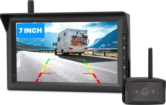
Introduction
Thank you for purchasing this digital wireless backup camera kit.
Please read all of the installation instructions carefully before installing the product. Improper installation will void manufacturer’s warranty. The installation instructions do not apply to all types of vehicles, and are written as guidelines to assist in installing the backup camera kit.
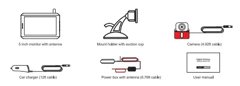
Package Contents
Key Features
- Support two cameras connection (One camera included. The second camera is sold separately)
- Flip the image Mirror/Normal/Up/Down (Optional)
- Six different sizes of guidelines
- 2.4 GHz wireless transmission
- Wide-angle (Diagonal 118°)
- User-friendly menu
- Simple and quick installation
Installation
Prior to installing your backup camera, test all components using your vehicle
power or an external power supply to ensure proper functionality.
Install the backup camera
Step1: Remove the license plate.
Step2: Find the installation location and clean it with a microfiber cleaning cloth and alcohol (To ensure the camera stick firmly).
Step3: You can install the camera above/below your license plate. When you install ii below, flip the image vertically up/down in the setting menu if the image upside down.
Step4: Fix your license plate with screws.
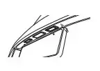
Steps: Hole for camera cable. Look for an opening or drill a hole near the license plate to thread the camera cable into the interior of the vehicle.
For good visibility and easy installation, we would recommend you to remove the interior trim near the license plate.
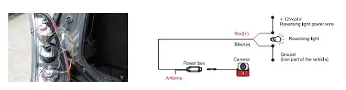
Step6: Connect the camera cable. Connect the camera cable to the 4-pin socket of the power box. Make sure the cables are not pinched or knotted.
Step7: Connect the power box wire.
- Open the inner plastic panel and remove it from the hatch or tailgate. (The panels are usually attached to the tailgate by clips. This may take a bit longer time to avoid clip damages. Once this panel is removed, the rest of the work will be easy to finish.)
- Find the power wire (positive) of reversing light and connect it to the power box red wire. Then connect the black wire of the power box to the ground (iron part of the vehicle).
How to find the reverse light (Positive)?
a. Switch the key to ACC position, then shift your vehicle into R-gear.
b. Prepare a test light, connect the clip or clamp to a known ground source, then use the pointed end to pierce the plastic insulation on your wires to check if power is present. If the bulb of the test light illuminates confirming the wire has power, it might be the reverse light wire.
c. Shift your vehicle into another gear. Test all the wires which have power in R-gear again, if the bulb turns off, the wire should be the positive pole of the reverse light.
Note: For the best performance, we recommend placing the antenna vertically and not placing it in an airtight environment.
Step8: Run the power box cable. Secure the camera cable and power box cable with cable ties in the rear carriage. To avoid interference of the transmission, make sure there are no electrical loads or metal between the monitor and antenna.
Step9: Check the connection of the power box. First, engage the hand brake and be sure the vehicle is not shifted into gear. Vehicles with automatic transmission must be in “P” for parking lock. Turn the ignition to ON (II) but do not start the engine. Put the car charger into cigarette lighter to power on the monitor. If the power box is correctly connected, the camera signal will be transmitted to the monitor while reversing, and the monitor will display the camera image.
Note: The above wiring also applies to the second camera. The red wire should be connected to a positive electrode and the black wire should be connected to a ground wire. You can also connect the camera to other ACC power supplies or external power supplies.
Install the monitor
Step1: Connect the antenna to the monitor.
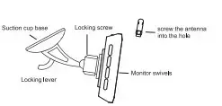
Step2: Open the locking screw and adjust the monitor to the desired
viewing angle then tighten the locking screw to secure the monitor.
Step3: Clean the area of the windshield or dashboard where you would like to mount your monitor. Press the suction cup against the mounting surface and push the suction cup lock lever down to lock the suction cup in place.
Step4: Connect the car charger with the monitor. Plug the car charger into 12V/24V power port in your vehicle.
Note: For a clean installation, you can hide the charging cable into the decorative seam around the edge of the dashboard, and if necessary, bundle the additional wires with a cable tie. The location of the monitor must not obstruct the visibility of the driver.
Operating Instructions
Monitor operations
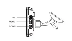
M: Menu/Return/Confirm.
Forward/increase.
Back/decrease.
Monitor menu settings
- Press the M button to access menu mode.
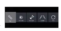
- Press A. or T to increase, decrease or advance the following menu items: Pair: pair the monitor with backup cameras. B/C Control: adjust the monitor brightness and contrast.
M/U Control: switch to Mirror/Normal/Up/Down Image. Guide Line: activate or deactivate guidelines. Reset: return to factory settings.
Note: No operation within 5 seconds, the monitor will automatically exit setup state.
Basic operations
Choose the sizes of guidelines
Step1: Activate guidelines (Guideline set to ON on the setting menu).
Step2: Put your vehicle into reverse and let the monitor displays camera image. Make sure the monitor is in a non-menu interface.
Step3: Press and hold M for about 3 seconds until guidelines flash.
Step4: Press A or T to choose preferable guidelines. Press M to confirm.
Note: If there is no operation within 3 seconds, the guidelines setting interface will exit automatically and current parameters will be saved. Turn off the monitor
The monitor will be on standby (Indicator light stays solid red) when ii is not displaying image. The monitor will only turn off when your engine is off (The power to the screen is cut off).
WARNING: Some vehicles provide constant power to the 12V/24V outlet. If your outlet has a constant power, unplug the monitor when not in use to avoid battery draining.
Pair the Cam2 (If you have installed two cameras)
- Power the monitor, then press the M button to enter the menu.
- Press A or T turn to Pair and press M to confinm.
- Press A or T turn to Cam2, press M to confirm. The indicator on the monitor will flash indicating the monitor is ready to pair.
- Shift your vehicle into reverse gear (If your camera is powered by reversing light). The pairing will start when the camera gets power.
- The monitor will display the image of the second camera if the pairing is successful.
Note: Do not power the backup camera before completing steps 1-3.
The camera in the package is Cam1. Cam1 is pre-paired and set as rear camera as default.
Pairing more than 30 seconds will be closed (timed out). In this case, try pairing again. If you keep receiving no images after several attempts, contact customer support to assist in troubleshooting.
Switch Cam1/Cam2 display
If the monitor has been paired with both Cam1 &Cam2, and the monitor is not on any selling interface, press and hold T for 3 seconds lo switch between Cam1 and Cam2 display. Switching will be invalid in the following situations:
- When the monitor is only paired with one camera.
- When the monitor is paired with 2 cameras, but only one is connected successfully.
Note: The settings including Guide Line, M/U Control are set separately by channel. For example, when you change guidelines parameters on Cam1 channel, ii will only be changed on Cam1 but not on both cameras.
Confirm version number
When the monitor displays image (non-menu interface) without red indicator (CH1/CH2) flashing, press and hold A for 3 seconds. The firmware version will be displayed in the upper and middle of the screen for 3 seconds. The screen version number starts with RX and the cameras’ with TX. For example, Cam1 is TX1: xxx, Cam2 is TX2: xxx.
Care and Maintenance
For maintaining its condition and performance, please follow the guidelines below.
- Keep your system away from excessive moisture, extreme heat or cold.
- Keep liquids away from the display.
- Wipe the unit gently with a soft cloth moistened with water. Do not allow residue or liquids to enter any part of the appliance as this may cause risk of electrocution.
CAUTION: Be sure to disconnect the power before cleaning. Never use solvents such as benzene, thinner or cleaners available commercially to clean the system.
Technical Specifications
Troubleshooting
The ignition is on and the R-gear is engaged, but the monitor display is blank.
- When you charge the monitor, the brand logo is not displayed on the screen. CD Possible cause: The car charger is broken. Solution: Check if the red light of the car charger lights up, if not, please contact the seller to replace a new car charger.
- When you charge the monitor, the brand logo is displayed on the screen. CD Possible cause: The camera is placed in a metal/sealed place. Solution: Please keep the camera away from metal or sealed place, and put the camera close to the monitor as possible as you can.
Possible cause: The camera cables maybe not correctly connected or loose. Solution: Check if cables are connected to the reverse light correctly and lightly.
Possible cause: The camera doesn’t pair to the monitor well. Solution: Try re-pair the camera with monitor. See ‘Pair the Cam2’ on page 7. Pairing of Cam1 and Cam2 are in the same way.
The monitor image isn’t clear enough.
- Possible cause: Bright light enters the camera lens. Solution: Move the backup camera out of the area of the interfering light.
- Possible cause: The protective films on the monitor and backup camera aren’t removed. Solution: Remove films from the monitor and backup camera. GE
- Possible cause: The camera lens may be dirty. Solution: Carefully clean the camera lens.
The image is flashing/the image delay is more than 2 seconds.
- Possible cause: The camera is placed in a metal/sealed place. Solution: Please keep the camera away from metal or sealed place, and put the camera close to the monitor as possible as you can.
- Possible cause: Your vehicle is longer than 7 meters. And when you put the camera closer to the monitor the image is stable. Solution: We suggest you to purchase extension cord if your vehicle is longer than 7 meters.
A red channel icon (CH1/CH2) flashes at the top-left corner of the monitor while reversing.
- Possible cause: The monitor is not paired with the camera, or the monitor cannot find the paired camera. Solution: Try re-pair the camera with monitor. See ‘Pair the Cam2’ on page 7. Pairing of Caml and Cam2 are in the same way.
Warranty and Service
You (as the end-user) receive a 12 months guarantee from the date of purchase. In addition, you can contact our service representative through the email address on the warranty card to extend the warranty for 6 months. If we repair or replace a product, the repaired or replaced product shall be warranted for the remaining time of the original warranty period. If for any quality problem not satisfied with your purchase, you shall return any item in its original condition within 30 days of receipt and we will gladly provide a refund, replacement, or an exchange. Any items received after 30 days will not be accepted for refund. For any items received after 30 days, we will provide repair service during the warranty period.
Our warranty does NOT cover the following situations:
- Warranty expired
- Damage caused by human factors, accident, misuse of the product
- Products purchased from unauthorized channels
- Unauthorized alternation to or change of parts or components of the product
- Fail to provide a receipt or proof of purchase 6. Malfunctions caused by phenomena such as fire, natural disasters
For speedy processing of your warranty claim you will need:
- Copy of the receipt showing the purchase date.
- Reason for the claim (description of defect). For more information or support, see www.auto-vox.com. Alternatively, send an e-mail to a service representative at [email protected]. 12
FCC Statement
This equipment has been tested and found to comply with the limits for a Class B digital device, pursuant to Part 15 of the FCC Rules. These limits are designed to provide reasonable protection against harmful interference in a residential installation. This equipment generates uses and can radiate radio frequency energy and, if not installed and used in accordance with the instructions, may cause harmful interference to radio communications. However, there is no guarantee that interference will not occur in a particular installation. If this equipment does cause harmful interference to radio or television reception, which can be determined by turning the equipment off and on, the user is encouraged to try to correct the interference by one or more of the following measures:
— Reorient or relocate the receiving antenna.
— Increase the separation between the equipment and receiver.
— Connect the equipment into an outlet on a circuit different from that to which the receiver is connected.
— Consult the dealer or an experienced radio/TV technician for help.
This device complies with part 15 of the FCC Rules. Operation is subject to the following two conditions:
(1) This device may not cause harmful interference, and (2) this device must accept any interference received, including interference that may cause undesired operation.
Changes or modifications not expressly approved by the party responsible for compliance could void the user’s authority to operate the equipment.