Air Injection 2510-SXT Installation & Startup Guide
The Air Injection AIO Filter, when properly applied, is an efficient and cost-effective system for the removal of iron and Hydrogen Sulfide. The AIO control valve maintains a compressed “air pocket” in the top of the tank while the system is in service. As the water passes thru the air pocket, iron and Iron are oxidized. Additionally, dissolved oxygen is added to the water. The Air Injection AIO filter media bed then removes the iron and hydrogen sulfide from the water.
A daily backwash will remove accumulated iron and replenish the filter media bed. The regeneration process also adds a fresh air pocket to the system.

Application parameters w/iron-iron Removal Media
pH(Minimum) 6.8
iron(Maximum) 7ppm
iron(Maximum) 4gpm
Service Flow (Maximum) 8gpm
Backwash Flow (Minimum) 3.0pgm
Iron Air Injection 2510-SXT Installation & Startup Guide
Pre-Installation
- If you are going to be turning off the water to the house and you have an electric water heater, shut off the power to the water heater before beginning installation in case water heater is accidentally drained.
- Pick a suitable location for your filter system on a dry level spot where it won’t be exposed to freezing temperatures. A minimum of 20 PSI is required. Maximum pressure is 90 PSI.
- Get all of your plumbing parts together before beginning installation. Installation typically takes 3 to 5 hours. However, after installation the 2510 SXT Air Injection Filter must be allowed to run through a complete backwash and rinse cycle.
- After the system is installed and running, your water may be discolored, or full of sediment or rust, particularly if this is older or corroded piping. Typically, this clears up over a day or two.
Assembly and Installation Instructions
- The 2510 SXT Air Injection filter is installed after the pressure tank. If you are also installing a water softener, install the softener after the 2510 SXT Air Injection filter.
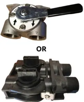
- Make sure to follow to connect the in pipe to the Fleck 2510 SXT inlet and the outlet to the outlet (see below). As you face the Fleck 2510 SXT control from the front, the water enters on the right and exits on the left. From the back (see below) the water enters on the left. The inlet and outlet are attached to the bypass valve which is marked with arrows as well.
- Make sure there is a working gate or ball valve before the Fleck 2510 SXT AIO filter and also one after. Pressure gauges are optional and perhaps not necessary but a hose bib (which is a faucet that you can attach a garden hose to) is strongly recommended after the 2510 SXT AIO filter before the second ball valve. This makes it easy to rinse your new 2510 SXT AIO filter on startup and gives you a place to test the water before it enters your household plumbing.
- If you will be using copper piping, do not sweat the copper pipe directly on to the Fleck 2510 SXT control valve. Avoid heating up the Fleck 2510 SXT control valve plastic with the torch.
- You do not need unions to install your Fleck 2510 SXT control. If you need to remove it, the Fleck 2510 SXT has quick-release couplings that make it easy to put the 2510 SXT AIO filter on by-pass and remove the filter system from the piping.
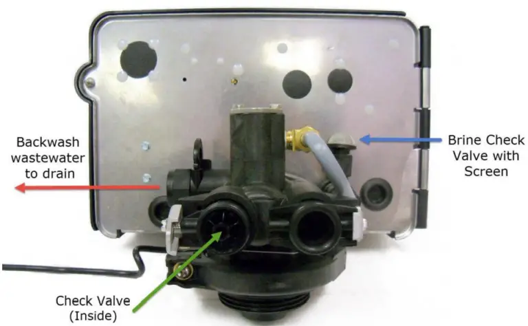
- The drain line tubing (not supplied) is connected to a drain from the drain outlet using flexible 1⁄2” ID tubing. Note that the drain can run up above the Fleck 2510 SXT control and into a drain, it does not have to drain down, as the filter backwashes under line pressure from your well pump.
- Ensure the brine line check valve with screen is installed on the brine valve (See below) This is the AIR DRAW point of entry.
System Limitations
Chlorine or other strong oxidizers will damage the filter media bed of these systems and should ever be used. The AIO Filter utilizes air, oxidation and filtration for the removal of Iron and Iron. This process will leave some air or effervescence in the water. The effervescence may give the water a milky appearance and is simply excess air in the water. While a certain amount of effervescence will always be present, it may be most noticeable during the first 30 days.
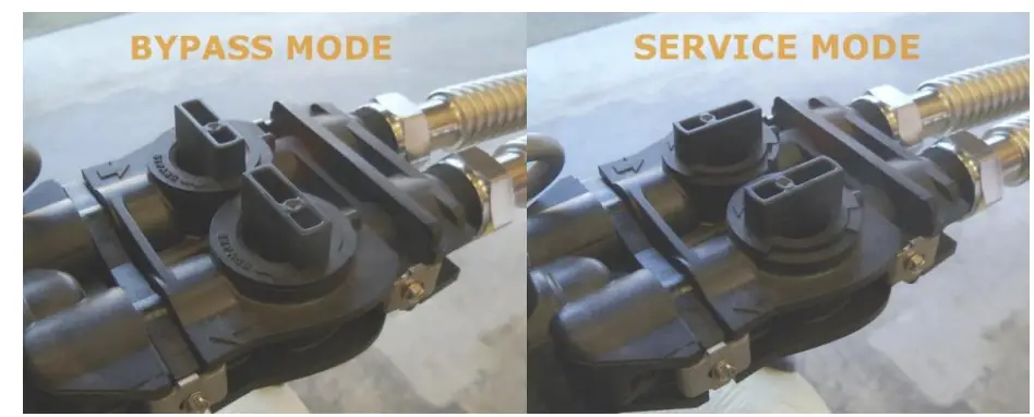
Bypass Assembly
The system must be backwashed once upon startup. First, put the system into service mode.
Normally the system ships in the bypass position. Once the system is properly plumbed in, make sure to turn both of the bypass valve knobs 90 degrees into service mode.
Regeneration Cycle (59 minutes)
- Backwash (14 minutes) During this cycle, the water carrying the iron runs to the drain. Untreated water is available during regeneration.
- Air Recharge (40 minutes) during this cycle, the unit empties water to the drain and is recharged with air. The sound of air being recharged will be heard. Air bubbles should go down to the drain before proceeding to the next step. Adjust cycle time if necessary.
- Rapid Rinse (5 minutes) During this cycle, water enters the tank, compressing the air into a pocket at the top of the tank.
- Brine Refill (Off)
- Unit Returns to the In-Service Position The frequency and time of regeneration can be changed due to the following reasons.
- In conditions of high-water usage and/or high levels of iron, the unit may need to regenerate more frequently than once every three days. The unit can be set for daily regeneration or to regenerate every two days. DO NOT set the regeneration frequency for a longer period than 3 days, as the filter medium can become fouled with iron, rendering the unit ineffective.
For initial programming enter master programming by setting the clock to 12:01 pm. To set the time of day press and hold the up OR down arrow until the service icon is replaced with the programming icon. Use the up and down arrows to set the time of day (PM is indicated in the upper right corner of the screen). Hold the arrow button to advance quickly through the time. Once the time is set, press the extra cycle button to save the setting. Once the parameter display is gone, press and hold the up AND down arrow buttons together for 5-10 seconds until the programming icon appears and [DF] is shown in the parameter code. Once each setting has been entered, use the extra cycle button to advance to the next setting. Please Note: Most of these settings will be left alone.
Depending on your system some settings may not be shown, and some settings may be different than shown here. Do not change any settings unless specifically instructed to do so by these instructions or one of our techs.
| Ensure the time is set to 12:01pm, hold BOTH up and down arrows until programming icon appears | |||
| Required | This setting is required and should be changed if it does not match | ||
| Variable | This setting will vary depending on the system and application. Use these instructions to set appropriately. | ||
| PLEASE NOTE: | Any setting on your system that is not specifically highlighted below will be left at default. This is a list of all possible options, and many will NOT be shown on your system and are included for informational purposes only. | ||
| Code | Parameter | Options | Description |
| DF | Display Format | GAL | Volume is displayed in gallons and time in a 12-hour AM/PM format – These instructions are based on the GAL setting |
| Ltr | Volume is displayed in liters and time in 24-hour format | ||
| VT | Valve Type | dF1b
-OR- AIO |
Downflow single backwash – used on air injection systems that require the air draw. Some systems show an AIO option, but if that is not available use the dF1b setting |
| Fltr | Filter – used for basic backwashing systems that do not need the air draw | ||
| dF2b | Downflow double backwash – similar to the dF1b but with 2 backwashes. Not commonly used. | ||
| UFbd | Upflow brine first – not commonly used. | ||
| UFtr | Uplow filter – not commonly used. | ||
| Othr | Other – not commonly used | ||
| CT | Control Type | FI | Metered (Flow) Immediate – counts down from the programmed gallon capacity and begins a backwash immediately after reaching 0. Only used on dual tank water softeners. |
| Fd | Metered (Flow) Delayed – counts down from the programmed gallon capacity and when 0 is reached queues a backwash cycle for the set regeneration time. Only used on water softeners. | ||
| Tc | Time Clock – will begin a backwash cycle at the set regeneration time after the set number of days has passed. Common setting on all backwashing systems except water softeners to ensure consistent cleaning of the media. | ||
| DAY | Day of the Week – will begin a backwash cycle on the set day(s) at the set regeneration time. More consistent Time Clock setting is recommended in most situations. | ||
| NT | Number of Tanks | 1 | For systems with only 1 media tank (all systems except dual tank softeners). |
| 2 | For systems with 2 media tanks (dual tank softeners only). | ||
| UT | Indicates current tank in service | U1 | Tank 1 is in service |
| U2 | Tank 2 is in service (dual tank softeners only). | ||
| C | Capacity | 1-999.9 (x1000) | System capacity, in grains. Metered softeners only. |
| H | Hardness | 1-199 | Hardness of the water, in grains. Metered softeners only. |
| RS | Reserve Selection | SF | Percentage safety factor – this uses a percentage of the capacity for a reserve. Softener systems only. |
| rc | Fixed reserve capacity – uses a set volume for a reserve. Softener systems only. | ||
| SF | Safety Factor | 0-50% | Only applies to softeners with RS set to SF |
| RC | Reserve Capacity | 1-(half of calculated capacity) | Fixed reserve capacity, softeners only. It is commonly set to the average number of gallons used in a day. If you are unsure of your actual usage, a good rule of thumb is to set it to the number of people in the house times 75. Example, if there are 4 people in the house, you would set it to 300 gallons (4×75). |
| DO | Day Override | 3 | This setting will start the backwash cycle after the set number of days. Typically set to 3 or less to ensure the media gets lifted and cleaned off regularly. This ensures effective filtration and long media life. If you have very dirty water or use large volumes of water you will want to set this to 1 or 2. For Filox media: Filox media used in Platinum systems requires backwashing at minimum every 2 days, with every night recommended for best results. |
| RT | Regen Time | 12:00 | This sets the time that the backwash cycle will start. This process can take up to 2 hours depending on system size and configuration, so schedule it when water will not be used. It is common to set to run when everyone is asleep or out of the house, and ensure it does not conflict with any other systems you may have. |
| BW | Backwash | 10 | This sets the length of the backwash portion of the cycle. During this cycle water flows through the system in reverse to lift the media and rinse off accumulated contaminants, with a strong flow of water going out the drain line. Reducing this cycle can lead to reduced media life and premature system failure. For very dirty water longer times may be needed. |
| BD -OR AD | Brine Draw -OR- Air Draw | 60 | This sets the length of the brine draw portion of the cycle. Air injection systems may show AD, but BD functions the same way. During this cycle a slow flow of water will go down the drain as the air pocket is created in the tank. |
| RR | Rapid Rinse | 1 | The rapid rinse cycle runs water through the tank in the normal direction to get rid of excess air and settle the media for normal operation. During this cycle there will be a steady flow of water down the drain. |
| BF | Brine Fill | 0 | This sets the length of the brine fill portion of the cycle. On air injection systems this will be set to OFF. |
| D1-D7 | Day of the Week Setting | OFF | Set to On or OFF for each day of the week. Only applies to systems with Control Type DAY, not typically used. |
| CD | Current Day | 1-7 | Used to set the current day. Only applies to systems with Control Type DAY, not typically used. |
| FM | Flow Meter Type (metered systems only) | P0.7 | 3/4″ Paddle Wheel Meter |
| Gen | Generic or Other Meter | ||
| P2.0 | 2″ Paddle Wheel Meter | ||
| t1.5 | 1.5″ Turbine Meter | ||
| P1.5 | 1.5″ Paddle Wheel Meter | ||
| t1.2 | 1.2″ Turbine Meter | ||
| t1.0 | 1″ Turbine Meter | ||
| P1.0 | 1″ Paddle Wheel Meter | ||
| t0.7 | 3/4″ Turbine Meter | ||
| K | Meter Pulse Setting | 0.1-999.9 | Pulses per gallon. Only applies to systems with FM set to Gen, not typically used. |
| Pressing the extra cycle button after the final setting will save your changes. If no buttons are pressed for 60 seconds while in programming mode the changes will be cancelled. | |||
| If you accidentally change a setting that does not have a recommended or variable value: Please do a hard reset as outlined in the resets section to return all values to default. You can then go back through the programming to set it up according to the chart above. | |||
| SXT Master Programming Chart | |||
Once you have finished programming use the arrows to set the current time of day. Once the time is set the display should then show the service icon, with the data display flashing between the current time of day and days remaining until the next backwash. Once it reaches 0 the system will queue a backwash for the set time. A flashing service icon indicates that a backwash is queued. A manual backwash can be queued by pressing the extra cycle button. An immediate backwash can be initiated by holding the extra cycle button for about 5 seconds. The service icon indicates that the system is “In Service” and functioning correctly, it does NOT mean that the system needs service.
After initial setup the master programming should not need to be used again unless a system reset is performed.
Even in the event of a power outage all settings are retained. If your water use or water quality changes you can use the user programming to make common changes to the programming as lined out below.
| Ensure the time is NOT set to 12:01pm, hold BOTH up and down arrows until programming icon appears | |||
| Please refer to the master programming chart for proper values each setting. | |||
| Code | Parameter | Options | Description |
| DO | Day Override | 3 | This setting will start the backwash cycle after the set number of days. |
| RT | Regen Time | 2:00 | This sets the time that the backwash cycle will start. |
| CD | Current Day | 1-7 | Sets the current day (day of week systems only) |
| Pressing the extra cycle button after the final setting will save your changes. If no buttons are pressed for 60 seconds while in programming mode the changes will be cancelled. | |||
| SXT User Programming Chart | |||
- DIGITAL Controller – Resets
If your controller is showing odd behavior such as erratic display, no display, or showing an error code, the first step is to try and reset it. Start with the soft reset, and if that does not solve the problem move on to the master reset. If the problem persists contact one of our technicians.
| Reset | Directions | Effect |
| Soft Reset | Hold Extra Cycle and Down buttons for 25 seconds | This will reset all parameters to the system default values, but leaves the days since the last backwash intact. This is a good place to start if you feel you may have changed a default setting. After resetting proceed through the master programming section |
| Hard Reset | Hold Extra Cycle button while plugging the unit in | This will reset all parameters in the system. This is typically reserved for erratic behavior that a soft reset does not resolve. After resetting proceed through the master programming section. |
SXT Controller Resets
Plumbing Guidelines
Before you continue Many homeowners install their own water systems with basic plumbing skills; if you are not comfortable with projects like this, please hire a professional plumber. Make sure to check local plumbing codes and follow any codes that apply. These instructions offer basic plumbing tips and cannot cover every situation. They are intended as a supplement and should not replace local plumbing codes or actual plumbing experience.
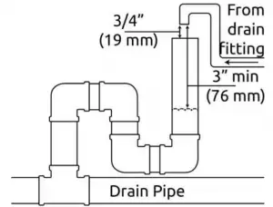
Drain Line Connection
Please note: Drain water comes out under line pressure, so it can be run vertically to connect to an overhead drain pipe. Never make a direct connection into a waste water drain. A physical air gap of at least 3 inches (76 mm) between the end of the drain line and the wastewater level in the drain pipe should be used to avoid contamination of the line. An additional gap of 3/4 inch (19 mm) between the drain pipe and drain line is recommended to prevent any problems in the case of a pipe overflow. Using a simple P-trap as shown is ideal as well, but a stand pipe with a diameter of at least 1.5 inches (38 mm) is adequate. As the water coming out is under pressure, make sure to secure the drain line so that it does not move and create a mess.
Do not tie multiple systems into a single drain line.
If hooking up multiple systems, each system needs a separate, independent drain line to ensure proper operation and prevent damage. Systems can all be run to the same standpipe/sump/outside drain, but the drain line from each system needs to be separate.
Do not use additional fittings on the drain line.
Avoid installing any additional fittings (check valves, ball/gate valves, etc.) as this can prevent proper backwash and cause premature system failure.
Do not overtighten the screws.
The bypass valve will have some up and down movement, this is normal. The clips simply hold the connection fittings together and the screws only need tightened enough to keep the clips in place. Further tightening will not stop leaks and tightening too much can damage the system, which will not be covered under warranty.
Verify flow direction.
Untreated water will enter the system on the side marked with an arrow pointing toward the front of the control head (on both the bypass valve and the control head itself). The inlet side will have a check valve and water will flow through it into the tank, the side shown in image will be facing you. (some models will have an arrow on the check valve itself, and the arrow should point toward the head). Treated water will exit the system on the side marked with an arrow pointing away from the front of the control head (on both the bypass valve and the control head itself).
Correct inlet/outlet connections are vital.
Improper flow direction will prevent proper operation and can damage your system and your plumbing. The direction of flow cannot be changed. Turning the bypass upside down will not change the direction of the water flow.
It is recommended to keep the bypass in the service position when making plumbing connections and turn it to bypass when first turning the water back on. shows the bypass position. In bypass position the handles will be turned 90-degrees and be perpendicular to the inlet and outlet fittings.
When soldering, do not solder directly to the included connection or close to the control head. First solder a short (min 3-inch [7.6-cm]) piece of copper pipe onto the adapters, away from the valve, before connecting the adapter to the bypass or yoke fitting.
For threaded connections, DO NOT tighten the adapters into fittings while they are connected to the control head.
Disconnect the bypass or yoke fitting, and connect the adapter using a high-quality thread sealant (pipe joint compound or Teflon/PTFE tape), and replace.
When installed the bypass valve can move up and down, this is normal
7623 Fulton Ave, North Hollywood CA 91605
For assistance call: 1-661 – 575 -0033
Email us: [email protected]
More information online: www.premierwatersystems.net