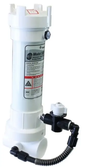
PENTAIR 320 Rainbow Chlorine Bromine Feeder
Information
It is important to read all information BEFORE proceeding with the installation. The information will guide you in installing your feeder properly and to avoid problems due to improper installation.
IF YOUR POOL OR SPA HAS COPPER PLUMBING . . . STOP!!
Never install the feeder into copper plumbing as pipe damage will occur. (See Equipment Safety CAUTION sheet enclosed). NOTE: If heaters are used, a Fireman’s Switch or equivalent must be installed to prevent possible damage and improper operation of Check Valve and other equipment subject to heat damage.
INSTALLATION INSTRUCTIONS MODEL #320
Note: Make sure all pumps and timer switches are in the OFF position.
WHERE TO INSTALL YOUR FEEDER
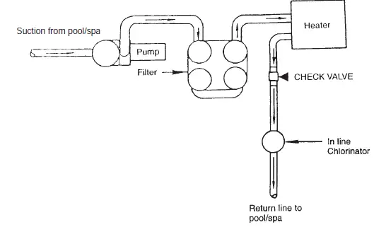
The #320 feeder is designed for permanent installation in the return line of your new pool or spa and must always be installed after the heater, pool cleaner, valves, etc. If your pool does not have a heater, then it must be installed after the filter or any other piece of equipment. DAMAGE TO THE HEATER AND OTHER EQUIPMENT COULD RESULT IF HIGHLY CHLORINATED
WATER FLOWS THROUGH IT.
If your pool is equipped with a solar system it may be necessary to install a HI FLOW KIT. This kit can be installed if your feeder is not getting adequate flow and/or pressure through the system. Refer to the information on sheet enclosed. Your feeder may be installed in existing PVC plumbing but will require a union and/or other fittings. The feeder comes complete for installation with 2″ or 1½” PVC plumbing. Choose a site in the return line where feeder can be installed in a vertical position. Always install as far from any metal equipment as practical since fumes, etc. can corrode them. If optional corrosion-resistant check valve is required refer to installation instructions before next step.
BASIC PLUMBING INSTALLATION INSTRUCTIONS
2″ OR 1½” PVC PIPE: If feeder is being installed on a pool, spa or pool/spa combination, correct plumbing procedures must be followed to insure proper flow through feeder. If pool or spa is plumbed with 2″ PVC pipe, be certain the pump, filter and heater all have 2″ inlet and outlet fittings. If any part of the equipment has less than 2″ fittings or pipe, then a minimum of 6″ x 1½” reducer bushings must be installed directly into the inlet side of the feeder using the 2″ x 1½” reducer bushings supplied. This will build pressure directly into the feeder insuring proper operation. Continue with 2″ PVC pipe on the outlet side of the feeder.
POOL/SPA COMBINATION:
If plumbing and equipment is a full 2″ and the feeder is being installed on the pool return line after the diverter valve, with a portion of the water diverted to the spa, install a minimum section of 6″ x 1½” PVC pipe directly into the inlet side of the feeder using the 2″ x 1½” reducer bushing supplied. Continue with 2″ PVC pipe on the outlet side of the feeder. This will compensate for that portion of water being diverted to the spa. 90° ELBOWS: Plumbing a 90° elbow directly into the inlet side of the feeder may cause turbulence inside the elbow. This will prevent water from being scooped into the feeder. A minimum of a 6″ length of PVC pipe should be installed between the 90° elbow and the inlet side of the feeder.
2″ PVC: Simply glue feeder to the return line using PVC SOLVENT CEMENT. Be sure arrows on feeder point in the direction of water flow returning to the pool or spa.
1½” PVC: Remove (2) 2″ x 1½” slip reducer bushings packed inside the feeder and glue into 2″ slip tee on bottom of feeder. Complete installation by gluing into 1½” return line making sure the arrows on feeder point in the direction of water flow returning to the pool or spa. Use only PVC SOLVENT CEMENT. Follow directions on solvent cement label. Allow to dry. Installation in now complete.
OPERATING INSTRUCTIONS
Before start up of feeder, your pool should be properly conditioned and the residual should be 1.0 to 1.5 ppm.The water in a newly-filled pool should be properly conditioned to insure maximum effectiveness of the feeder. Consult your local dealer for water conditioning information for your area.
- Remove cap of feeder and fill with proper size tablets.
For Pools: 1″ or 3″ dia. tablets For Spas: 1″ dia. tablets in optional Spa Chamber. - Make sure the O-ring is clean, lubricated with Lifegard Silicone and is in place, replace cap. Hand tighten only.
- Turn on the pump and timer switches for a minimum of 6 to 8 hours.
- Adjust control valve according to your pool/spa size. Use a test kit to determine the chemical residual. It is recommended that the chemical residual be checked daily for the first 5 days. Remember . . . hot days, higher water temperature or increased pool/spa activity will cause your pool/spa to use more sanitizer. When possible, increase the feed rate a day or two in advance. Because the chlorine demand in your pool/spa varies and is dependent on many factors (sunlight, bather load, water temperature, etc) your valve setting may have to be changed from time to time to adjust to these conditions. For example, the winter setting may be #2 while the summer setting is #3. Check the chlorine residual daily to find the ideal setting. Note: Higher numbers dispense more chemical. Small gradual changes are imperative for control.
HOW TO RECHARGE FEEDER
- Turn control valve to the closed position. SHUT OFF PUMP.
- Wait one minute. This will allow water and fumes to drain from feeder.
- Leave control valve closed and turn on pump. The check valve will prevent water from entering the feeder.
- Remove cap and fill with proper size tablets or sticks. (See Operating Instructions #1)
- Making sure O-ring is clean, lubricated with Lifegard silicone and is in place, replace cap. Hand tighten only.
- Open control valve to original setting. Inspect inlet line below control valve each time feeder is recharged. Replace lines yearly if necessary.
SPECIAL FEATURES AND INSTRUCTIONS
If while using 3″ diameter tablets the #320 feeder does not provide enough chlorine residual, switch to 1″ tablets. The smaller tablet will erode faster producing more chlorine residual. If this does not correct the situation, the #320 has been fitted with an optional opening at the top of the feeder (which is plugged). To accommodate attachment of the valve and tubing assembly for top entry of water into the feeder, an additional length of tubing has been included.The following procedure should only be used if the suggested change has not solved the situation. Top entry in normal situations can cause over-chlorination.
- Turn off pump and timer switches.
- Remove tubing by unscrewing the compression nut at each end of tubing.
- Remove plug at top of the feeder directly above control valve.
- Remove the control valve. If nipple stays in valve, carefully remove by using pliers at the center of nipple. There is no need to remove the 90° tube fittings.
- Wrapping with 2 or 3 wraps of threaded tape in the opposite direction of tightening. Screw into the opening where control valve was attached. Hand tighten plus 2 or 3 turns. Do not overtighten.
- Wrap threads of nipple with threaded tape.Thread nipple into top opening.Finger tighten only. Thread valve onto nipple. After nipple starts to turn from tightening valve, 2 to 3 more turns is enough. The nipple or valve can be broken by overtightening.
- Slide compression nut over long section of tube. Slide tube over tapered part of 90°tube fitting and tighten. Hand tighten only. Repeat for another end of tubing.
- Set control valve to #1. Turn on the pump and timers. Check residual daily to determine proper setting. Small gradual changes are imperative for control.
BELOW WATER LEVEL INSTALLATION
Feeder should be installed above water level whenever practical. If installed below water level, a drain valve must be installed to prevent spillage and dangerous splash back of high chlorinated water during recharging. Drill and tap a ¼” MPT hole at the same level the control valve is located. Make sure there is no water or tablets inside the feeder before drilling. Install optional drain valve, Part R172060, or suitable chemical resistant drain valve.
BELOW WATER LEVEL RECHARGING INSTRUCTIONS
- Shut off pump and timer switches.
- Shut off the control valve.
- Place a clean container under drain and open drain valve.
- Exercise extreme caution when opening or servicing feeder. Do not inhale fumes. Wear protective gear. Remove cap.Water will now drain from feeder. Empty container back into pool or spa.
- Close drain valve. fill with proper size tablets or sticks.
- Make sure the O-ring is clean, lubricated with Lifeguard Silicone and in in place, replace cap.
- Turn on pump and timer switches.
- Reset control valve to the original setting. Inspect inlet and outlet line each time feeder is recharged. Replace lines yearly if necessary.
D A N GER
READ CAREFULLY
This feeder is designed to use only CLEAN Trichlor-s-trizinetrione OR CLEAN Bromine tables – slow dissolving type. Never use dirty tablets. UNDER NO CIRCUMSTANCES MIX Trichlor or Bromine with Calcium Hypochlorite, with other forms of concentrated chlorine or with other chemicals. Keep inside of feeder clean of dirt and debris at all times. FIRE AND/OR EXPLOSION MAY RESULT. NEVER use oils or grease to lubricate o-ring. Oil in contact with Trichlor OR Bromine may result in FIRE. Lubricate o-ring with Lifegard Silicone o-ring Lubricant ONLY, available at your dealers. If shock treatments or Algaecides containing chemicals other than sanitizers tablets in feeder must be used, turn off Feeder OR remove tablets until the shock or Algae treatment is complete and all granules have dissolved. Failure to do so may result in granules mixing in feeder causing FIRE AND/OR EXPLOSION. The shock or algae treatment dissolved in water is safe with tablets. If you are not the original owner of this feeder, not sure which chemicals was used, or if dirt and/or debris inside feeder, be SAFE and flush thoroughly with fresh water. CAUTION SHOULD BE USED
WHEN REMOVING CAP. DO NOT INHALE FUMES.
CALCIUM HYPOCHLORITE IS NOT TO BE USED IN ANY FORM. Use of chemicals other than listed by the manufacturer may be hazardous.
Bromine Standpipe Installation
To increase erosion of small bromine tablets, install Bromine Standpipe as follows:
- Remove screen from bottom of chamber exposing check valve (F)
- Insert adapter (T) into check valve opening.
- Cut supplied 5/8″ black tube (Q) to 6″ length and push tube into adapter opening.
YOU MAY SUBSTITUTE BROMINE TABLETS OR STICKS FOR TRICHLOR IN THIS FEEDER. DO NOT MIX.
CALCIUM HYPOCHLORITE IS NOT TO BE USED IN ANY FORM.
IMPORTANT OPTION.
SEE CORROSION CAUTION SHEET.
CAUTION
Do not install feeder into copper plumbing. Pipe damage could occur. Never install feeder before heater. Heater damage could occur.
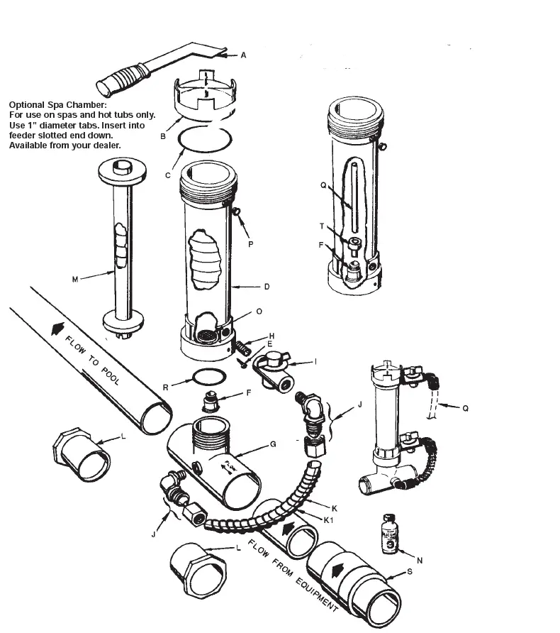
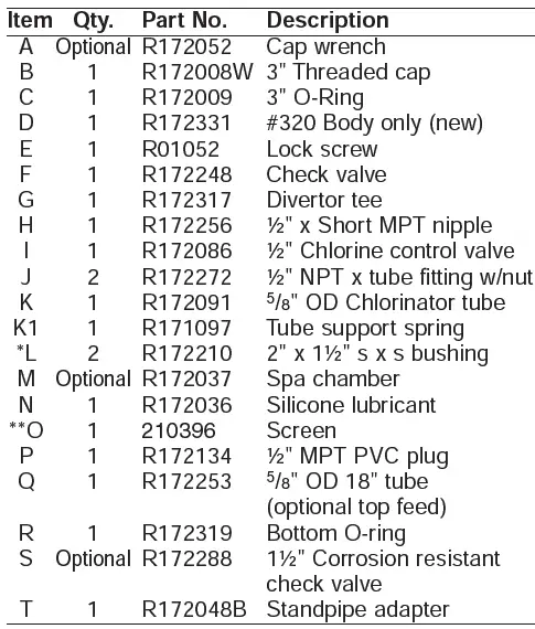
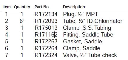
#320 CHLORINE / BROMINE FEEDER PARTS BREAK DOWN DRAWING
*Not used with 2″ PVC, for 1½” PVC only.
**Be sure screen has not come loose in shipment—if loose: Simply snap over 4 posts in bottom of chlorinator to replace.
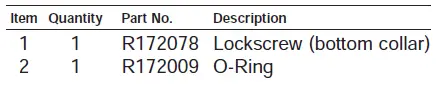
NOTE: To service check valve F, Remove lockscrew E, and unscrew (counter-clockwise) D chlorinator body from G divertor tee. 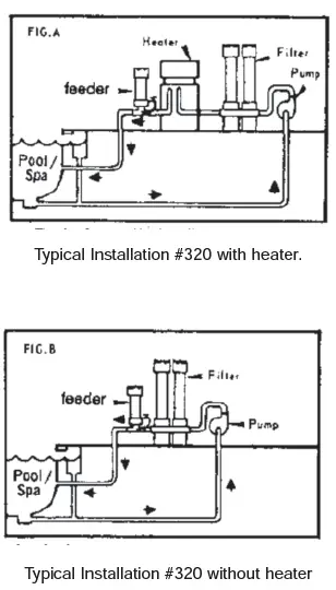
DIRECTIONS
- Turn off pump and timer switches.
- Loosen compression nut and remove Feeder tube and 90° elbow from the diverter tee at base of Feeder.
- Using thread seal tape as thread sealant, wrap ½” MPT plug threads (1) with several turns of the tape only.
Install in place of 90° elbow on diverter tee. - Disconnect another end of Feeder tube from control valve 90° elbow, by loosening the compression nut. Use the compression nuts from old tube to attach new 6′ section (2).
- Push compression nut over tubing end, then push tubing onto tapered end of elbow. Tighten nut firmly by hand.
- Connect another end of plumbing. IF THE POOL/SPA HAS A HEATER, INSTALL IT BETWEEN FILTER AND HEATER. IF YOUR POOL/SPA HAS A SOLAR SYSTEM, INSTALL IT BEFORE SOLAR
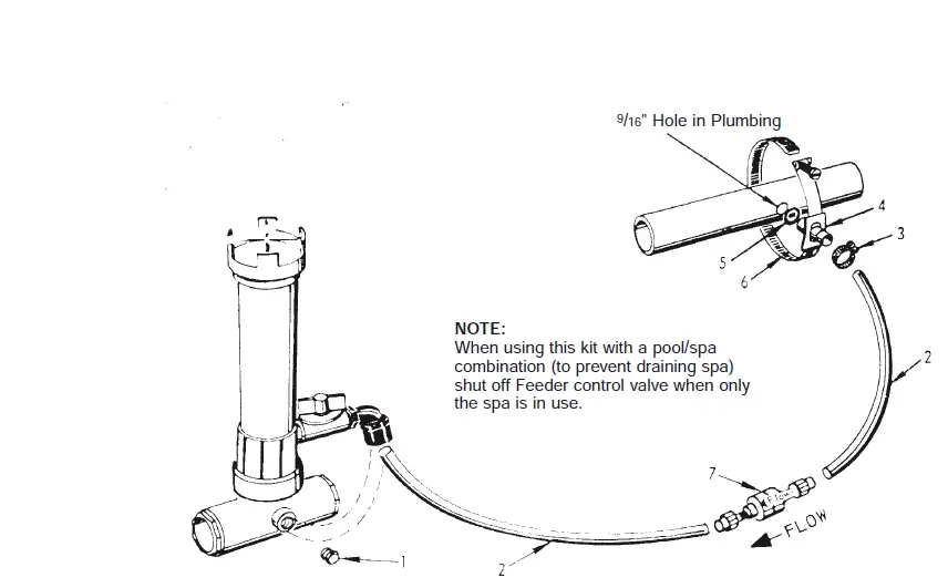
SYSTEM INLET LINE. IF NO HEATER, INSTALL IT BETWEEN PUMP AND FILTER. Drill 9/16″ hole in plumbing, remove burrs, and install saddle clamp assembly. (See illustration) Tighten the clamp with a screwdriver. Slide small stainless steel clamp #3 over tubing #2 and slide tubing over saddle tube fitting #4. Secure tubing to fitting by tightening camp with screwdriver. Make sure clamp is below rib at end of saddle tube fitting. - To install ½” CHECK VALVE, cut tube approximately 6″ away from plumbing connection. Remove compression nuts from check valve. Slide nuts over both ends of tube. Insert check valve ends into both pieces of tubing and tighten compression nuts firmly by hand. Be sure arrow “FLOW” is pointing toward the Feeder.
HI FLO FEEDER KIT #R171099 PARTS BREAKDOWN DRAWING
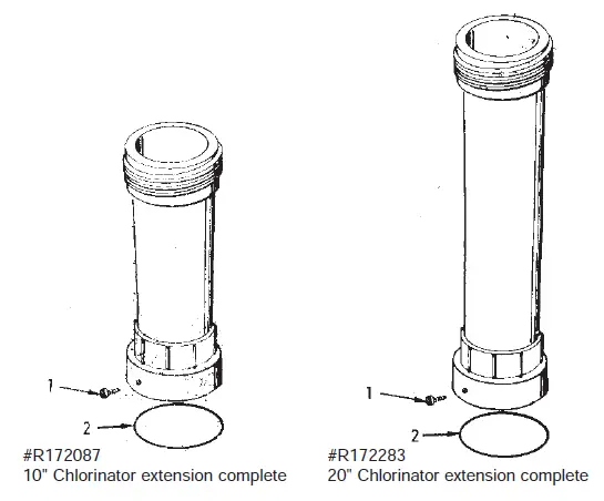
EXTENS IONS
- Going on vacation?
- Need more chlorine?
- Filling Chlorinator/Brominator too frequently?
LIFEGARD CHLORINATOR EXTENSIONS SOLVE THE ABOVE PROBLEMS BY:
- Increasing tablet capacity.
- Larger chamber size allows more erosion of tablets. (See special instructions below)
The 10″ extension doubles and the 20″ extension triples (approximately) the capacity and time between refills. *AVAILABLE THROUGH LIFEGARD DEALERS ONLY.
NOTE: On free standing #300 series chlorinators, the base of the chlorinator should be secured to
prevent the possibility of the chlorinator tipping over due to increased height.
INSTALLATION INSTRUCTIONS
- Follow recharging instructions to the point of filling with tablets
- Making sure O-Ring is clean, lubricated with Lifegard Silicone and in place, screw on extension tightly and secure with lock screw. (You may wish to wait until back in operation before tightening screw to insure against leaks).
- Fill with tablets and continue with normal recharging procedure.
SPECIAL INSTRUCTIONS:
The large chamber size will result in more chlorine being dispensed at the same valve setting, therefore, once installed, several days monitoring will be necessary to readjust chlorinator output.
R 172288 1½ ” & 2 ” SLIP SPRING CHECK VALVE
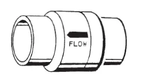
- Special corrosion resistant 1½” & 2″ slip spring check valve can be used
- to check back flow of fluids, air, etc.
- Full free flow design
- Special Spring and Seal for corrosive applications.
- Enclosed spring insuring free operation.
- Very effective when used in conjunction with chlorinator to check back flow
- of chemicals to pool/spa equipment, preventing corrosion problems
- and damage.
- Can be mounted in any position.
Typical check valve installation
NOTE: If heaters are used, a Fireman’s Switch or other safety device must be installed to prevent possible damage and improper operation of Check Valve and other equipment subject to heat damage.
EQUIPMENT SAFETY CAUTION!
PLEASE READ CAREFULLY
Since most pool’s plumbing is not airtight, and a mixture of air and chlorine is highly corrosive to metals, it is important to protect these items from corrosion in the OFF period when no circulation is taking place. (There is no chance for chlorine corrosion when the circulating system is in operation.)
Of course, corrosion or erosion of metal components can still occur independently of any chlorinator installation for the following reasons:
- Water velocity too high.
- Water pH less than 7.2.
- Total alkalinity less than 100 PPM.
If your pool or spa has any of the following equipment, special plumbing procedures must be followed for safe operation:
- Brass or bronze gate, rotary or backwash valves.
- The preceding valves are constructed of PVC or other plastic material with metallic shafts.
- Filters, heaters, heat exchanges or other items with metallic tanks, shafts, coils or tubes.
- NOT FOR USE IN COPPER PLUMBING.
Installation of the OPTIONAL Rainbow #R172288 positive seal, corrosion resistant check valve SHOWN ON REVERSE SIDE will prevent the backflow of corrosive liquids and gases that can damage equipment containing metallic components. Examples listed above.
WARNING: If your pool is equipped with a permanent built in pool-cleaning system, damage could occur to that system if materials are not compatible with low pH Tri-Chloro feeders. Check with the manufacturer for compatibility.
WARNING: Before installing this product, read and follow all warning notices and instructions accompanying this valve. Failure to follow safety warning and instructions can result in severe injury, death, or property damage. Call (800) 831-7133 for additional free copies of these instructions.
IMPORTANT NOTICE!
Attention Installer: This manual contains important information about the installation, operation and safe use of this product. This information should be given to the owner/operator of this equipment.
- The valve must be installed by a qualified serviceman in accordance with the National Electrical Code and all applicable local codes and ordinances.
- Always disconnect power to the equipment at the circuit breaker before servicing any of the equipment. Ensure that the disconnected circuit is locked out or properly tagged so that it cannot be switched on while you are working on the equipment. to do so could result in serious injury or death to servicemen, operator users or others due to electric shock.
- Position the filter and the air relief valve to safely direct water drainage and purged air or water. Water discharged from an improperly positioned filter or valve can create an electrical hazard that can cause severe personal injury as well as damage to property.
For Installation of Electrical Controls at Equipment Pad (ON/OFF Switches, Timers and Automation Load Center)
Install all electrical controls at equipment pad, such as on/off switches, timers, and control systems, etc. to allow the operation (startup, shut-down, or servicing) of any pump or filter so the user does not place any portion of his/her body over or near the pump strainer lid, filter lid or valve closures. This installation should allow the user enough space to stand clear of the filter and pump during system start-up, shut down or servicing of the system filter.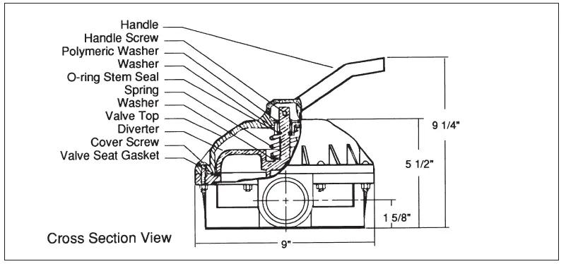
FILTER OPERATES UNDER HIGH PRESSURE.
When any part of the circulating system, (e.g., clamp, pump, filter, valve(s), etc.), is serviced, air can enter the system and become pressurized. Pressurized air can cause the lid to separate which can result in severe injury, death, or property damage. To avoid this potential hazard, follow these instructions:
- Before repositioning valve(s) and before beginning the assembly, disassembly, or adjustment of
the clamp or any other service of the circulating system: (A) Turn the pump OFF and shut OFF any automatic controls to ensure the system is NOT inadvertently started during the servicing; (B) open the manual air relief valve; (C) wait until all pressure is relieved. - Whenever installing the filter clamp FOLLOW THE FILTER CLAMP INSTALLATION INSTRUCTIONS EXACTLY.
- Once service on the circulating system is complete FOLLOW SYSTEM RESTART INSTRUCTIONS EXACTLY.
- Maintain circulation system properly. Replace worn or damaged parts immediately, [e.g., clamp, pressure gauge, valve(s), o-rings, etc].
- Be sure that the filter is properly mounted and positioned according to the instructions provided.
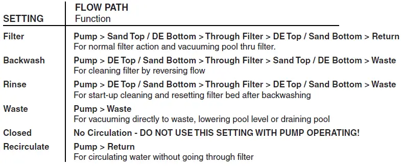
Valve Positions Overview
Valve Installation
This valve is available in two models for use with sand type or diatomaceous earth (DE) type pool filters. Be sure that you have the correct model for your filter. Installing the incorrect model may cause your pump to dead head, or drain the pool when in backwash position.
- Confirm correct valve is being used; DE valves for DE filters and Sand valves for Sand filters.
- Install valve to filter by securing bulkhead nuts on valve to fittings on the filter.
- Plumb pump piping to center pipe in valve.
- Plumb return and waste lines.
Technical Data
Replacement Parts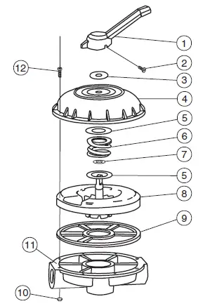
| Item | P/N | Description | Qty. |
| 1 | 272520 | Handle | 1 |
| 2 | 272405 | Screw – Handle | 1 |
| 3 | 272402 | Washer, Plastic | 1 |
| 4 | 272412 | Valve Top | 1 |
| 5 | 271193 | Washer – 18 GA | 2 |
| 6 | 272400 | Spring – Compression | 1 |
| 7 | 272406 | O-ring – Diverter | 1 |
| 8 | 272413Z | Diverter | 1 |
| 9 | 272409 | Seal -Diverter | 1 |
| 10 | 98211400 | Nut – 1/4″ – 20 Hex | 8 |
| 11 | 272415 | Plat – 2″ Valve Bottom | 1 |
| 12 | 272403 | Screw – 1/4″ – 20 | 8 |
| * | 272422 | Valve Top Assembly | 1 |
*This part number includes items 1 thru 9
Note: When replacing gasket P/N 272409, secure it to valve bottom with an instant cyanocrylate adhesive suitable for bonding rubber to plastic.
Head Loss Curves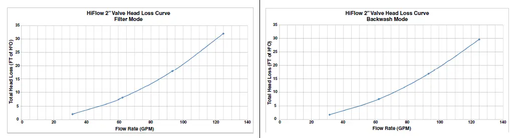
1620 HAWKINS AVE., SANFORD, NC 27330 • (919) 566-8000
10951 WEST LOS ANGELES AVE., MOORPARK, CA 93021 • (805) 553-5000
WWW.PENTAIR.COM
All Pentair trademarks and logos are owned by Pentair or one of its global affiliates. Hi-Flow™ is a trademark of Pentair Water Pool and Spa, Inc. and/or its affiliated companies in the United States and/ or other countries. Unless expressly noted, names and brands of third parties that may be used in this document are not used to indicate an affiliation or endorsement between the owners of these names and brands and Pentair Water Pool and Spa, Inc. Those names and brands may be the trademarks or registered trademarks of those third parties. Because we are continuously improving our products and services, Pentair reserves the right to change specifications without prior notice. Pentair is an equal opportunity employer.
© 2018 Pentair Water Pool and Spa, Inc. All rights reserved. This document is subject to change without notice.
IMPORTANT SAFETY INSTRUCTIONS READ AND FOLLOW ALL INSTRUCTIONS
SAVE THESE INSTRUCTIONS
Technical Support
Sanford, North Carolina (8 A.M. to 4:30 P.M.)
Phone: (800) 831-7133
Fax: (919) 566-8920
Moorpark, California (8 A.M. to 4:30 P.M.)
Phone: (800) 831-7133 (Ext. 6502)
Fax: (805) 530-0194
Web sites: visit www.pentairpool.com and www.staritepool.com
Related manual: ScreenLogic® Interface User’s Guide (P/N 520493)
 FCC Regulatory Safety Notice – This equipment has been tested and found to comply with the limits for a Class B digital device, pursuant to Part 15 of the FCC Rules. These limits are designed to provide reasonable protection against harmful interference in a residential installation. This equipment generates, uses and can radiate radio frequency energy and, if not installed and used in accordance with the instructions, may cause harmful interference to radio communications. However, there is no guarantee that interference will not occur in a particular installation. If this equipment does cause harmful interference to radio or television reception, which can be determined by turning the equipment off and on, the user is encouraged to try to correct the interference by one or more of the following measures:
- Reorient or relocate the receiving antenna.
- Increase the separation between the equipment and receiver.
- Connect the equipment into an outlet on a circuit different from that to which the receiver is connected.
- Consult the dealer or an experienced radio/TV technician for help.
- Modifications not expressly approved by the party responsible for FCC compliance could void the user’s authority to operate the equipment.
In this Installation Guide
Use the information in this manual for installing the ScreenLogic® Interface Wireless Connection kit contents.
- For ScreenLogic Interface system operating instructions, refer to the ScreenLogic Interface User’s Guide (P/N 520493)
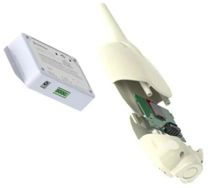
ScreenLogic® Interface Wireless Connection Kit
The ScreenLogic® Interface Wireless Connection interface consists of an indoor and outdoor wireless 2.4 GHz transceiver. Note: The transceivers ship from the factory as a matched pair. The ID numbers on each transceiver must be the same number to function correctly. Transceivers are replaced as a matched pair. For more information, call Customer Support (880) 831.7133.
The transceivers provides a wireless connection between the ScreenLogic Interface Protocol adapter and the IntelliTouch® or EasyTouch® Control System Load Center located at the equipment pad. This wireless connection eliminates the existing hard wire connection from inside your home to the equipment pad.
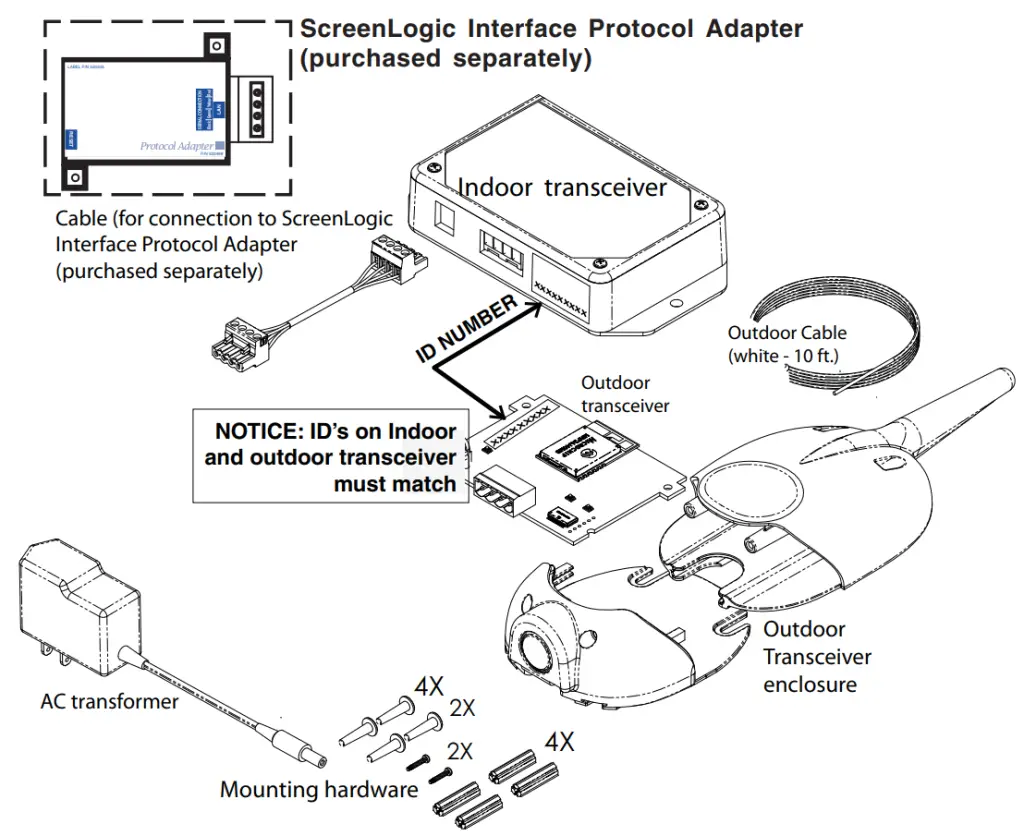
Wireless Connection Kit Contents
The following items are included in the Wireless Connection kit.
- One ScreenLogic Interface indoor wireless transceiver with AC power adapter and one foot connection cable with attached plugs.
- One ScreenLogic Interface outdoor wireless transceiver with 10 ft. cable, provided in kit with enclosure and mounting hardware.
- ScreenLogic Interface Wireless Connection Installation Guide (this manual)

ScreenLogic Interface Wireless Connection Kit Contents
Summary installation steps
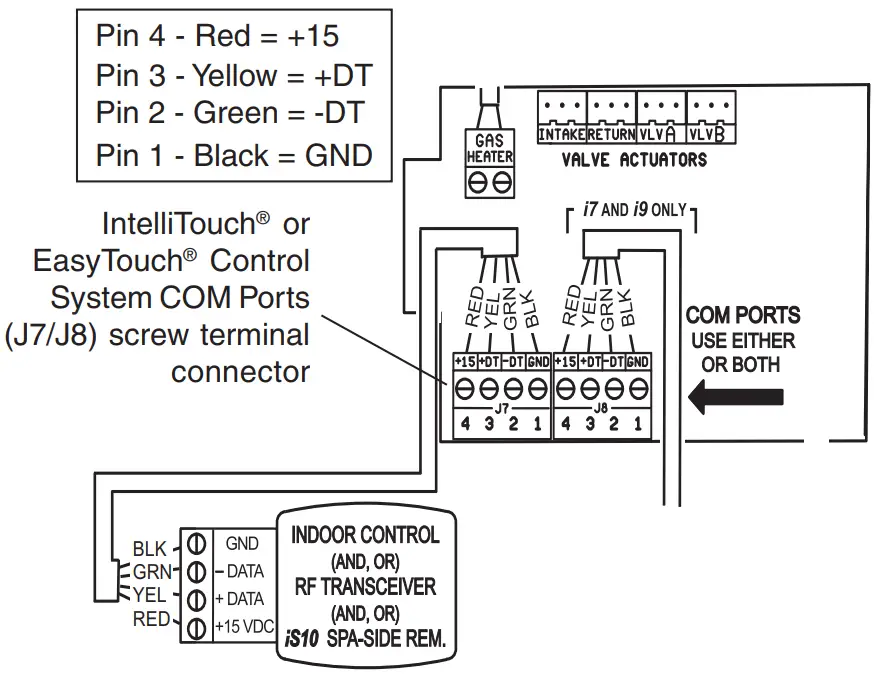
The ScreenLogic® Interface connection diagram on page 2 shows the transceiver locations and connections. To install the ScreenLogic Interface Wireless Connection kit:
- Mount the outdoor transceiver antenna near the IntelliTouch® or EasyTouch® Control System Load Center and connect the transceiver to the COM port connector located in the IntelliTouch® or EasyTouch® Control System Load Center.
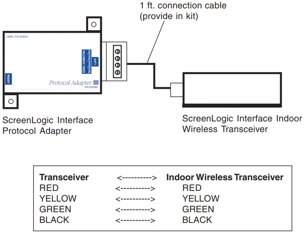
- Use the supplied 12 inch cable to connect the ScreenLogic Interface indoor wireless transceiver to the ScreenLogic Interface Protocol adapter. Plug the transceiver AC power adapter into an AC wall-outlet and into the transceiver unit to power up the unit.
ScreenLogic Interface (Indoor Wireless Transceiver)
ScreenLogic® Interface Connection Diagram
Cable distance limits:
– Ethernet cable distance limit = 300 feet
– Four-wire cable distance limit = 1500 feet Note: (*) Optional wiring for existing Indoor Control Panel. Tap into the Indoor Control Panel connector or pig tail off the four-wire cable connected to the Personality board.
Step 1:
Mount the Outdoor Wireless Transceiver and Connect to the IntelliTouch® or EasyTouch® Control System Load Center
The following describes how to mount the transceiver to the IntelliTouch® or EasyTouch® Control System Load Center and connect the four-wire cable to the COM port connector located in the IntelliTouch or EasyTouch Control System Load Center:
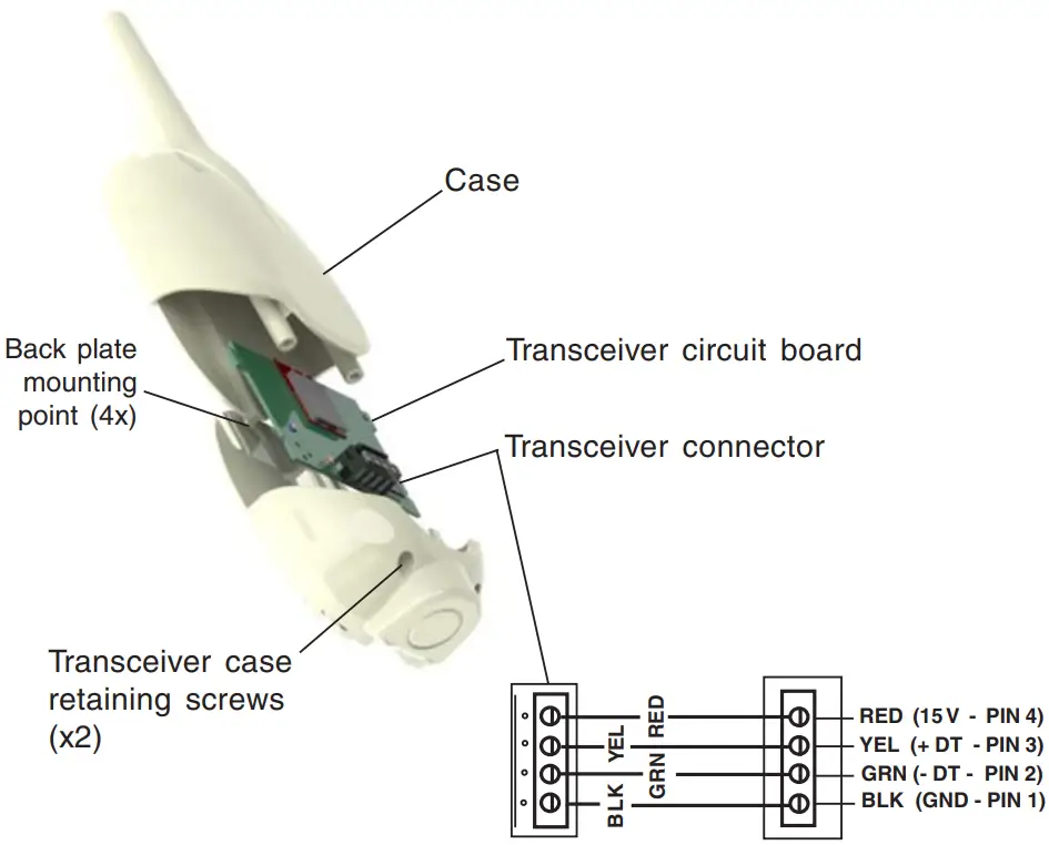
Mount the Transceiver Module
The Transceiver is a two-way radio device with an attached antenna that communicates to and from the IntelliTouch or EasyTouch Control System. Mount the transceiver at a convenient location (on a flat vertical surface) near the load center at a minimum of 5 feet above ground level to optimize the transmit and receive operating range.
- Remove the two retaining screws located on the underside of the transceiver case. Slide the case off the back plate.
- Position the back plate against the mounting surface so that the transceiver is oriented in an upright position with the antenna pointing upwards. Use a pencil to mark the four mounting points. Drill four 3/16 in. diameter holes into the mounting surface and insert the four plastic anchors provided in the kit.
Note: To avoid signal interference, mount the transceiver a minimum of 10 feet away from the load center, any metal surface/structure, or air blower located in the immediate area of the equipment pad. - Position the back plate over the mounting points and secure it with the four mounting screws provided in the kit.
- Carefully position the transceiver circuit board into the mounted back plate. Route the connection wire down through the lower exit hole (left side) at the bottom of the back plate. Carefully pull the wire out the lower hole and position the circuit board in the back plate.
- Position the transceiver circuit board to the left side of the back plate, and slide the case over the circuit board and antenna into the back plate. Secure the circuit board in the case using the two retaining screws.
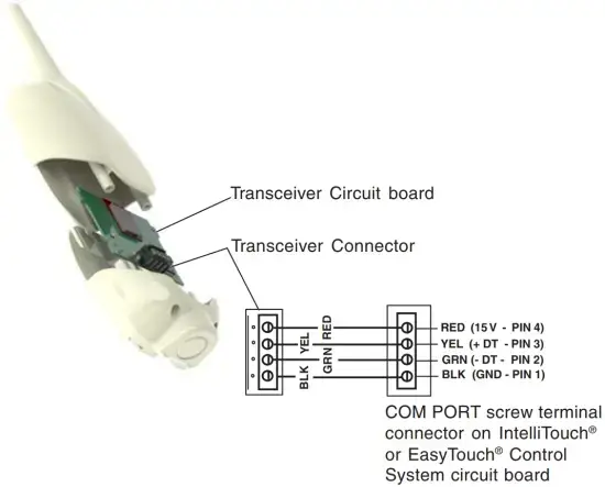
- Proceed to “Connect the Transceiver connection cable to the COM Port on Control Systems Circuit Board” on the next page.
Transceiver Module Wiring
Connect the Transceiver connection cable to the COM Port on Control System Circuit Board
 WARNING Switch OFF the main system power to the Load Center before making any connections.
- Unlatch the enclosure door spring latche(s), and open the door.
- Remove the two retaining screws securing the high voltage cover-panel, and remove it from the enclosure.
- Loosen the two access screws securing the control panel.
IntelliTouch® or EasyTouch® Load Center - Lower down the hinged control panel to access the circuit board.
- Route the four conductor transceiver connection cable into the lower plastic grommet, up through the low voltage raceway to the circuit board.
- Insert the four wires into the screw terminals of the COM PORT plug located on the circuit board as shown on page 6. Using a small flat-blade screwdriver, secure the wires with the screws.
Note: Multiple wires may be inserted into a single screw terminal but increases the chances of a poor or intermittent connection.
Note: Install the ScreenLogic® Interface outdoor wireless transceiver within 10 feet from Load Center
- After the connection has been completed, close the control panel into its original position and secure it with the two access screws.
- Install the front panel and secure it with the two retaining screws.
- Close the Load Center front door. Fasten the spring latche(s).
- Switch the power on to the IntelliTouch® or EasyTouch® Control System Load Center.
- Proceed to the “Connect the ScreenLogic Interface Indoor Wireless Transceiver to the ScreenLogic Interface Protocol Adapter” on page 8.
Step 2:
Connect the ScreenLogic® Interface Indoor Wireless Transceiver to the ScreenLogic Interface Protocol Adapter
To connect the ScreenLogic Interface indoor wireless transceiver to the ScreenLogic Interface Protocol adapter:
- Using the provided connection cable, connect one end of the cable to the ScreenLogic Interface Protocol adapter and the other end to the ScreenLogic Interface indoor wireless transceiver. The cable plugs are keyed for easy connection.
- Plug the ScreenLogic Interface Wireless Connection transceiver AC adapter wall-plug into an AC grounded electrical outlet.

Wiring Configuration
1620 HAWKINS AVE., SANFORD, NC 27330 · (919) 566-8000 10951 WEST LOS ANGELES AVE., MOORPARK, CA 93021 · (805) 553-5000
All Pentair trademarks and logos are owned by Pentair, Inc. Pentair Aquatic SystemsTM, ScreenLogic®, EasyTouch® and IntelliTouch® are trademarks and/or registered trademarks of Pentair Water Pool and Spa, Inc. and/or its affiliated companies in the United States and/ or other countries. iPhone® is a registered trademark of Apple Corporation. Unless expressly noted, names and brands of third parties that may be used in this document are not used to indicate an affiliation or endorsement between the owners of these names and brands and Pentair Water Pool and Spa, Inc. Those names and brands may be the trademarks or registered trademarks of those third parties. Because we are continuously improving our products and services, Pentair reserves the right to change specifications without prior notice. Pentair is an equal opportunity employer.
© 2014 Pentair Aquatic Systems. All rights reserved.
This document is subject to change without notice.
CONTROL INTELLITOUCH® AND EASYTOUCH® CONTROL SYSTEMS FROM YOUR MOBILE DIGITAL DEVICE
Now you can use your iPad®, iPhone® or iPod touch® mobile digital device or Android® device, to control all key functions of your pool or spa, from across the deck or around the globe. New software that communicates with the ScreenLogic interface of your new or existing IntelliTouch or EasyTouch control system is now available as a free download from the App Store® or Google PlayTM. Once it’s installed, you can control everything from pool and spa temperatures to jets, lighting, water features and more–right from your iPhone or other mobile digital device.

No other pool or spa control device offers such convenience.
- Easily turn on your spa and set it to the perfect temperature on your way home from work.
- Control all circuits when you are away–including waterfalls, pool lights, fountains and more.
- Use the History page to monitor temperature, pool/spa, heater and lights from afar.
WE’VE BROUGHT ENERGY SAVINGS WITHIN EASY REACH
The Eco Select® Brand designates eco-friendly products that conserve energy, minimize water usage, reduce noise or otherwise contribute to a more environmentally responsible pool system. As the global leader in pool and spa equipment manufacturing, we stand at the forefront in providing greener choices for our customers. We hope you’ll join us in embracing more eco-friendly poolscapes by choosing Eco Select brand products like this one for your swimming pool.

SCREENLOGIC® INTERFACE FOR MOBILE DIGITAL DEVICES

HERE’S ALL YOU NEED TO DO.
The software for your Apple® mobile digital device or Android® platform is a free download from the Apple App Store® or Google PlayTM. It’s easy to get:
- Using your device, visit the App Store or Google Play.
- Search for “Pentair.”
- Choose to download and install the Pentair® ScreenLogic interface.
FINGERTIP CONVENIENCE, WORLDWIDE CONTROL–FROM YOUR FAVORITE MOBILE DIGITAL DEVICE
How can you manage your pool or spa with our ScreenLogic interface app? Just about any way you want–from just about anywhere.
Easy to navigate. To get started, just choose what you want to manage from a simple home screen.
Temperature control for pool and spa. Getting off work an hour from now? Crank up the temperature on the spa, kick on the pool pump and even choose the heater mode: Solar, Solar Preferred, or Heater. When you arrive, your place of relaxation will be waiting.
Like standing in front of the control panel. If you’ve set up a Waterfall, Jets, or Spillway on your IntelliTouch® or EasyTouch® control system, then those circuits–and any others you’ve similarly chosen–will show up on the Circuits screen of your ScreenLogic interface app. Which means you enjoy push-button control anytime from anywhere.
AVAILABLE FROM:
Know what your pool’s been doing. Your ScreenLogic interface app shows you a visual history of your pool and spa’s operation. See how your water temperatures have changed over time. Confirm the exact periods that the Lights, Heater, Solar, Spa, and Pool modes have been used. Know your wishes are being followed and your money is being saved–no guesswork necessary.
If your pool is equipped with an IntelliTouch or EasyTouch system and a PC or Mac® computer ScreenLogic interface to access them, you’re already good to go.
If you don’t yet enjoy the benefits of an IntelliTouch or EasyTouch system, now’s the ideal time to upgrade to electronic convenience and get mobile digital device remote control at the same time. If you’re an IntelliTouch or EasyTouch system owner, you can gain iPad®, iPhone® and iPod touch® mobile digital device or Android® device access through a PC and Mac computer ScreenLogic Interface and Wireless Connection Kit (Part # 522104). This kit lets you remotely manage your pool and spa through your PC or Mac computer as well as your mobile digital devices.

1620 HAWKINS AVE, SANFORD, NC 27330 800.831.7133 WWW.PENTAIRPOOL.COM
All Pentair trademarks and logos are owned by Pentair or one of its global affiliates. ScreenLogic®, IntelliTouch®, EasyTouch®, and Eco Select® are registered trademarks of Pentair Water Pool and Spa, Inc. and/or its affiliated companies in the United States and/or other countries. iPad®, iPhone®, iPod touch®, Mac®, Apple® and App Store® are registered trademarks of Apple, Inc. in the United States and/or other countries. Google PlayTM and Android® are trademarks and/or registered trademarks of Google, Inc. Because we are continuously improving our products and services, Pentair reserves the right to change specifications without prior notice. Pentair is an equal opportunity employer.
pumps · filters · heaters · heat pumps · automation · lighting · cleaners · sanitizers · water features · maintenance products
1/16 Part # P1-096 ©2016 Pentair Water Pool and Spa, Inc. All rights reserved.

Product Information
The OMNIFILTER QuickConnect Water Filtration System is a
tankless reverse osmosis system designed to provide clean and
purified water. This system is manufactured by Pentair, a trusted
brand in water filtration technology.
Before installing the tankless reverse osmosis system, it is
important to ensure that your water supply meets the following
operating specifications:
- Recommended Feed Pressure Range: [Insert recommended feed
pressure range] - Production Rate (GPD): [Insert production rate]
- Pressure Range: [Insert pressure range]
- Temperature Range: [Insert temperature range]
- Operating Voltage: [Insert operating voltage]
- TDS (Total Dissolved Solids): [Insert maximum TDS]
- Maximum Hardness: [Insert maximum hardness level]
- Sulfide, Iron, and Manganese: [Insert tolerance for sulfide,
iron, and manganese] - Chlorine in Water Supply: [Insert tolerance for chlorine
presence] - pH Limits: [Insert pH limits]
- Overall Dimensions: [Insert dimensions of the system]
- Weight: [Insert weight of the system]
Please note that failure to comply with these operating
specifications may reduce the effectiveness of the system and void
the warranty.
Product Usage Instructions
- Ensure that your water supply meets the operating
specifications mentioned above. - Select an appropriate location for installing the OMNIFILTER
QuickConnect Water Filtration System. It should be near a cold
water supply line and a drain for wastewater. - Shut off the main water supply to your home or building.
- Install the pre-filter cartridge(s) according to the provided
instructions. This step may vary depending on the specific model of
the system. - Connect the system’s inlet valve to the cold water supply line
using the provided fittings. Ensure a secure and leak-free
connection. - Connect the system’s outlet valve to a faucet or dispenser
using the provided fittings. Again, ensure a secure
connection. - Connect the wastewater drain line to a suitable drain. Make
sure it is positioned to prevent any backflow or leaks. - Turn on the main water supply and check for any leaks. If leaks
are detected, immediately shut off the water supply and fix them
before proceeding. - Allow the system to flush for a few minutes to remove any air
or impurities. - Follow the system-specific instructions for turning on and
operating the reverse osmosis filtration process. - Regularly replace the filter cartridges as recommended by the
manufacturer to ensure optimal performance and water quality.
For more detailed installation and operation instructions, refer
to the OMNIFILTER QuickConnect Water Filtration System Tankless
Reverse Osmosis System Installation and Operation Manual provided
by Pentair.
Remember to consult a professional plumber or contact the
manufacturer’s customer support if you encounter any difficulties
during installation or have any questions regarding the product
usage.
View Fullscreen
OMNIFILTER
QUICKCONNECT WATER FILTRATION SYSTEM TANKLESS REVERSE OSMOSIS SYSTEM INSTALLATION AND OPERATION MANUAL
©2022 Pentair Residential Filtration, LLC
pentair.com
IMPORTANT: Before installing this tankless reverse osmosis system, make certain your water supply complies with the following operating specifications. Failure to do so may reduce the effectiveness of the system and will void the warranty.
· Please read all instructions and precautions before installing and using your Tankless Reverse Osmosis system.
· For standard, under-sink installation on 3/8″ (9.52 mm) steel, brass, or copper cold water line.
· When selecting a location of the system, take into consideration the length of tubing required for connections between existing plumbing and system components. Some installation sites may require more tubing than provided in the kit.
· Ensure that the system’s installation location is within 5 feet (1.52 meters) of a 110 volt grounded outlet.
· Numbered diagrams correspond with numbered steps.
SPECIFICATIONS
Recommended Feed Pressure Range: Production Rate (GPD): Pressure Range: Temperature Range: Operating Voltage:
TDS: Maximum Hardness: Sulfide, Iron and Manganese: Chlorine in Water Supply: pH Limits: Overall Dimensions:
Weight:
10 to 60 psi (0.694.14 bar) 396.4 gpd (1500 Lpd) 15 to 100 psi (2.756.89 bar) 40100°F (4.437.8°C) Input Voltage: 100-240V AC Output Voltage: 24V DC <2000 ppm <10 gpg (170 mg/L) <0.01 ppm <2 ppm 311 5.51″ W x 17.60″ D x 17.10″ H (140mm x 447mm x 434mm) 25.35 lbs (11.5 kg)
If the hardness of your water is above 10 gpg (171 mg/L), lime scale will build up rapidly on the membrane. Scale buildup will plug the membrane and make the system ineffective. We do not recommend these tankless reverse osmosis systems be used with water in excess of 10 gpg (171 mg/L) hardness.
A maximum total level of approximately 0.01 ppm sulfide, iron or manganese is permissible. See your local dealer to reduce these substances in your water.
PARTS INCLUDED:
· Main Body Assembly · Power Adapter · Composite Filter (CF) & Carbon Filter (CB) Cartridges · RO Membrane Cartridge (RO) · Inlet Water Adapter · Smart Faucet · 1/4″ Tubing – White · 1/4″ Tubing – Red · 3/8″ Tubing – White · 1/4″ Quick Connect Locking Clip · 3/8″ Quick Connect Locking Clip · 1/4″ Quick Connect Fitting · Drain Line Clamp · Front Cover · Owner’s Manual · Quick Reference Guide
Tools and Materials Required
· Hand or electric drill (cordless preferred) · (2) Adjustable wrenches · Slotted and Phillips screwdrivers · File · Safety glasses · Drill bits: 1/8″, 3/16″, 1/4″, 3/8″ · Tube cutter or utility knife · Pencil · Towel · Bucket If sink does not have hole for separate faucet: · Center punch · 3/4″ hole saw or drill bit · Safety mask
NOTE: All tools may not be necessary for installation. Read installation procedures before starting to determine what tools are necessary.
CALIFORNIA PROPOSITION 65 WARNING
WARNING: This product contains chemicals known to the State of California to cause cancer or birth defects or other reproductive harm.
PRECAUTIONS
GENERAL
WARNING: Do not use with water that is microbiologically unsafe or of unknown quality without adequate disinfection before or after the system.
CAUTION RO System must be protected against freezing,
which can cause cracking of the RO components and water leakage. NOTE:
· Your water must be within required limits for satisfactory operation. If not, your membrane life may be shortened and your warranty will be voided (see Specifications on page 2).
· This tankless reverse osmosis system will not protect against disease-causing bacteria or remove naturallyoccurring harmless bacteria.
· Install on cold water line only. · Make certain that installation complies with all state and
local laws and regulations. · The replacement cartridges and tankless reverse osmosis
element included with this system have limited service lives. Changes in taste, odor, and color of the water being filtered indicate that the cartridge should be replaced. · After prolonged periods of non-use (such as during a vacation) it is recommended that the system be flushed for 5 minutes before it is used. · A drinking water cartridge may contain carbon fines (very fine black powder). After installation, flush the system for 5 minutes to remove the carbon fines before using the water. · It is recommended that you run the tap at least 20 seconds prior to using water for drinking or cooking purposes. · The contaminants or other substances removed or reduced by this water treatment device are not necessarily present in your water.
2 · QUICKCONNECT TANKLESS RO Installation and Operation Manual
HOW REVERSE OSMOSIS WORKS
The Tankless Reverse Osmosis (RO) System uses a semipermeable membrane to reduce dissolved salts and minerals, improving the taste and odor of your water. The RO membrane is made of layers of micron-thin film wound around a hollow center core. Water molecules can pass through the membrane, but dissolved salts and minerals are rejected.
The Tankless Reverse Osmosis System features 3-stage filter action. Your water supply is pre-filtered to reduce dirt and chlorine that may foul the membrane. The RO membrane separates this pre-filtered water into PRODUCT WATER and DRAIN or REJECT WATER. Incoming water pressure forces the product water through the membrane. Dissolved solids and other contaminants cannot pass through the membrane and are sent to the drain as reject water.
For each gallon of water produced, less than 1 gallon of water goes to the drain. When used under the Specifications on page 2 of the manual, your Tankless Reverse Osmosis membranes should last 12-24 months.
INSTALLATION
GROUNDING INSTRUCTIONS: This appliance must be grounded. In the event of a malfunction or breakdown, grounding will reduce the risk of electric shock by providing a path of least resistance for electric current. This appliance is equipped with a cord having an appliance-grounding conductor and a grounding plug. The plug must be plugged into an appropriate outlet that is installed and grounded in accordance with all local codes and ordinances.
WARNING: Improper connection of the appliancegrounding conductor can result in a risk of electric shock. Check with a qualified electrician or service representative if you are in doubt whether the appliance is properly grounded. Do not modify the plug provided with the appliance; if it will not fit the outlet, have a proper outlet installed by a qualified technician.
A. The power-supply receptacle for the appliance shall be installed in a cabinet or on a wall adjacent to the undercounter space in which the appliance is to be installed;
B. There shall be an opening through the partition between the compartments specified in (A) that is large enough for the attachment plug to pass through. The longest dimension of the opening shall not be more than 1-1/2 in (38 mm);
C. The edges of the opening specified in (B) shall, if the partition is wood, be smooth and rounded, or, if the partition is metal, be covered with an edge protector provided for this purpose by the manufacturer; and
D. Care shall be exercised, when the appliance is installed or removed, to reduce the likelihood of damage to the supply cord.
QUICKCONNECT TANKLESS RO Installation and Operation Manual · 3
INSTALLATION CONTINUED . . .
1. Installing the Water Supply Adapter
1
The supply adapter fits 1/2″-14 NPS supply threads or 3/8″ x 3/8″ compression. If local codes permit, it may be used to connect the system to the cold water supply line. If local codes do not permit the use of the supply adapter, alternate connectors can be obtained from your local supplier.
Directions:
(A) Turn off cold water supply line. If cold water line does not have a shut-off valve under the sink, you should install one.
(B) Turn on the cold water faucet and allow all water to drain from line.
(C) Disconnect riser cold water supply valve.
(D) Ensure the sealing gasket is fully seated into the feed adapter valve female thread.
(E) Install feed adapter valve onto supply valve as desired. The feed adapter valve may be installed at the bottom of the supply hose or the top of the cold water line. Hand tighten only.
(F) Connect the riser to the feed adapter valve.
NOTE: Be careful not to cross-thread.
2. Selecting the Faucet Location
The drinking water faucet should be positioned with function, convenience, and appearance in mind. An adequate flat area is required to allow faucet base to rest securely. The faucet fits through a 3/4″ hole. Most sinks have pre-drilled 1-3/8″ or 1-1/2″ diameter holes that may be used for faucet installation. If these pre-drilled holes cannot be used or are in an inconvenient location, it will be necessary to
drill a 3/4″ hole in the sink to accommodate the faucet.
CAUTION This procedure may generate dusts which can cause severe irritation if
inhaled or come in contact with the eyes. The use of safety glasses and safety mask for this procedure is recommended.
CAUTION DO NOT ATTEMPT TO DRILL THROUGH AN ALL-PORCELAIN SINK. If
you have an all-porcelain sink, mount the faucet in pre-drilled sprayer hole or drill through countertop next to sink.
CAUTION When drilling through a countertop, make sure the area below the
drilled area is free of wiring and piping. Make certain that you have ample room to make the proper connections to the bottom of the faucet.
CAUTION Do not drill through a countertop that is more than 1″ thick.
CAUTION Do not attempt to drill through a tiled, marble, granite or similar
countertop. Consult a plumber or the countertop manufacturer for advice or assistance.
The following instructions apply to stainless steel sinks ONLY.
(A) Line bottom of sink with newspaper to prevent shavings, parts or tools from falling down the drain.
(B) Place masking tape over the area to be drilled to help prevent scratches if drill bit slips.
(C) Mark point with center punch. Use a 1/4″ drill bit to drill a pilot hole through sink.
(D) Use a 1-1/4″ hole saw to enlarge hole. Smooth rough edges with a file.
2
4 · QUICKCONNECT TANKLESS RO Installation and Operation Manual
Pilot Hole
B
C D
1/41″/4″C
11/4″ 11/4″
D
Mounting A
Hole
INSTALLATION CONTINUED . . .
3
3. Mounting the Faucet
NOTE: Not all parts provided with the faucet may be needed for installation.
(A) Slide chrome plate and black rubber washer onto faucet by threading both drain tubes through the holes on the plate and washer.
(B) Attach large diameter white 1/4″ drain tube to barb fitting at the faucet base.
(C) Slide white extension spacer onto long threaded section of faucet. Open end of extension should come in contact with base of faucet.
(D) Screw washer, and locking nut onto end of faucet threads.
(E) Screw quick connector onto end of faucet threads.
(F) Wet end of 1/4″ white tube. Push into bottom of quick connector. Tug gently to be sure connection is complete. Insert 1/4″ quick coupling lock plate between quick connect port and claw of tubing.
NOTE: To remove the tube, push on the fittings’ collar and pull the tube out.
(G) Holding the faucet, feed the tube through the hole in the sink. Position the faucet handle at a desired location.
(H) Center the faucet. Tighten the locking nut with a wrench until it is tight.
4. Installing the Drain Clamp
NOTE: If you have a single-basin sink with a disposal unit, call Technical Support
5
for options.
NOTE: Before installing the drain clamp, check the drainpipes under the sink
B
for corrosion. Corroded pipes should be replaced before continuing with
installation.
(A) Attach the drain clamp to a vertical section of the drainpipe, about 6″ above the trap. Make sure the opening on the drain clamp is facing towards the drinking water faucet.
(B) Using the fitting hole of the drain clamp as a guide, drill a 1/4″ hole through one side of the drainpipe.
(C) Remove the drain clamp from the drainpipe and enlarge the hole with a 3/8″ drill bit. Use a file to remove rough edges from the drilled hole.
5
(D) Make sure the black rubber gasket is adhered to the inside of the drain clamp and place the drain clamp assembly over the drilled hole. Look through the hole and position the clamp so that the center of the clamp hole is slightly higher (about 1/16″) than the center of the drilled hole. Tighten the clamp securely.
(E) Screw the plastic compression nut onto the drain clamp until hand-tight.
5. Connecting the System to the Drain
CAUTION This is a gravity drain line. Any loops, kinks or sharp bends must be
eliminated before proceeding.
(A) Locate the 1/4″ red tubing.
(B) Insert one end of the tubing into the “Drain” port on the back of the system. Insert 1/4″ quick coupling lock plate between the quick coupling and the jack
6
catch of the tubing.
(C) Run the other end of the tubing to the desired drain location.
6. Installing the System
WARNING: When selecting a installation location of the system, take into consideration the length of tubing required for connection between components. Some installation sites may require more tubing than provided in the kit.
(A) Select a location under the sink, or other suitable area where the system will be installed.
NOTE: The system carton can be used to determine the operational footprint required for installation of the system and replacement cartridges.
(Figure 6) Carton is oversized 4-6″ in each direction for packing materials.
(B) The system should be set on a firm, solid surface that is able to support the weight of the system.
Faucet Body Upper Gasket Countertop Gasket Ring Below Gasket Installation Knob Inlet Water Threaded Pipe Direct Quick Coupling 1/4″ Quick Coupling Lock Plate 1/4″ PE Pipe
3/8″ Tube
C
QUICKCONNECT TANKLESS RO Installation and Operation Manual · 5
7
INSTALLATION CONTINUED . . .
7. Connecting the Faucet to the System
(A) Determine the length of plastic white tubing needed to connect from the system to the faucet. Be sure to allow enough tubing to prevent kinking and cut the tubing squarely. Use a marker to mark one end of the tubing 5/8″ from the end. Wet the end of the 1/4″ tube and push into the port on the back of the system labeled “Drinking Faucet”. Insert 1/4″ quick coupling lock plate between quick connect port and claw of tubing.
CAUTION Do not bend or crimp tube while inserting.
(B) Gently pull back on the tube to ensure it is connected properly.
8. Connecting the System to the Water Supply Adapter
(A) Locate remaining length of 3/8″ plastic white tubing.
8
(B) Place a mark on the tubing 5/8″ from the end. Moisten the end of the tubing
with water and insert with a twisting motion push into inlet quick connect
fitting on the back of the system labeled “Inlet”. Insert the 3/8″ quick
coupling lock plate between the quick connect port and the claw of the water
inlet tubing.
(C) Cut the tube to a length that will allow connection to the Water Supply Adapter that was installed in Step 1. Ensure the tubing does not kink. Place the Compression Nut and Compression Sleeve over the Plastic tubing and then place the Insert Fitting into the end of the Tubing. Tighten the Compression Nut onto the Water Supply Adapter.
9. Connecting the Power Adapter
(A) Locate the electrical adapter, and plug the smaller end into the power receptacle on the back of the system.
9
(B) Locate the Faucet power cord and plug into the port titled “Faucet Power” on the back of the system. Screw the movable nut on the aviation connector clockwise until tightened.
10. Filter Installation
(A) Remove filter cartridges from their packaging and remove the rubber stoppers at the top of each cartridge.
(B) The order sequence of the cartridges is as follows: Top: RO Membrane Cartridge Middle: CB Filter Cartridge Bottom: CF Filter Cartridge
(C) Insert filter cartridges with handle parallel to the floor, turn 90° so that the handle is now perpendicular to the floor.
11. System Start-up
10
(A) Connect machine to power supply and plug into electrical outlet. When the machine is first powered on, a small beep will occur and four indicator lights will flash.
(B) The machine will automatically flush for 5 minutes. During this time the water quality indicator light will flash red.
(C) Open faucet and allow to run for 30 minutes. During this time the water quality indicator light will flash with the actual water quality color.
(D) While flushing occurs, check the tightness of all parts and fittings carefully to ensure no leaks at the connection points.
(E) Once flushing is complete, the faucet can now be closed. The machine will enter a normal water production state and the water indicator light will remain on with the actual water quality color.
CAUTION Visually check the entire system for leaks. If a leak is present, see
Troubleshooting on page 8.
NOTE: To complete 24-hour flushing, reference page 9. Flush 24-hours upon start or before first use. For the first 24-hours use water for cooking and/or cleaning.
6 · QUICKCONNECT TANKLESS RO Installation and Operation Manual
Filter Cartridge Replacement
NOTE: The life of the filter cartridges depends on water volume used and the quality of the feed water. It is recommended that the filter cartridges be replaced every 12 months, or when there is a noticeable change in taste, odor, or flow of filtered water.
Ensure the correct cartridge is purchased for the system. Pentair Tankless RO System #4006877 uses the following replacements: #4006882 / ROM-24M / Replacement RO Membrane #4006943 / CF-12M / CB-12M / Replacement Filter 2-Pack
Cartridge Sequence
Cartridge Replacement A. Twist cartridge 90 degrees counter-clockwise and remove
from system. B. Install new cartridge in the proper location, push firmly and
twist clockwise.
Indicator Lights
Indicator Lights · CF: CF Filter Cartridge Lifetime Indicator · RO: RO Membrane Cartridge Lifetime Indicator · CB: CB Filter Cartridge Lifetime Indicator · Water Drop: Water Quality Indicator (TDS indicator)
Smart Faucet Indicator Lights
· To quickly and easily get filter life indication, the Smart Faucet includes an LED ring around the base of the faucet which indicates filter life.
· Blue – Normal, filter life is good · Purple – Needs attention, filter life will expire soon.
Indicator will change when there are 15 days of filter life remaining. · Red – Expired, filter should be changed
Inserting Cartridges into System
Cartridges Fully Engaged in System
Troubleshooting
QUICKCONNECT TANKLESS RO Installation and Operation Manual · 7
Indicator Status
System Error Indications
Error Type Timeout fault
Indicator Lights 3 red indicators flash
Frequent start-stop Water leakage
Low temperature
3 purple indicators flash 4 red indicators flash 3 indicators flash
Filter Cartridge Lifetime Display
Fault Indicator Go out Go out
Red indicators flash Red indicators flash
Recover Method
Power off and then power back on the system
Power off and then power back on the system
Locate and repair water leak
Power off and then power back on the system
Lifetime status
Life Time Left (Days)
Treatment Capacity Remaining
Warning Type
Filter cartridge indicator
Buzzer
Normal Early Warning
Alarming
Greater than 15 days
Greater than 0 and less than 15 days
Zero days
Greater than 150 liters
Continuous Blue light on
No warning reminder
Greater than 0 and less than 15 liters
Zero
Continuous Purple light on Continuous Red light on
Beeps twice during water production (beep 0.3
seconds, stop 1 second)
Beeps during production (beep 0.3 seconds, stop 1
second)
Water Quality Indicator Display
Blue < 100 ppm
TDS LED Color Purple > 100 < 150 ppm
Red > 150 ppm
8 · QUICKCONNECT TANKLESS RO Installation and Operation Manual
Machine Functions
Function
Action logic
Filter Cartridge Indicator
Initial system power on
Beeps 0.1 second, indicator display 3 seconds
Blue-Purple-Red indicator light
First time use washing
Replacement filter flushing
Automatic flushing 5 mins
User turns on the faucet, allows water to flush for 24 hours
NOTE: View To Complete 24-hour Flushing section on the bottom of page 9.
1. CF filter cartridge: turn on the faucet and flush for 5 minutes.
2. RO filter cartridge: turn on the faucet and flush for 30 minutes.
3. CB filter cartridge: turn on the faucet and flush for 15 minutes.
4. Reset the RO filter cartridge together with other filter cartridge: turn on the faucet and flush for 5 minutes, then re-flush for 30 minutes.
5. Reset the CF filter cartridge and CB filter cartridge: turn on the faucet and flush for 15 minutes.
Water production
Water making action
Standby
The machine stops making water and goes into standby mode
Blue light always on
Blue light always on
Light always on (base on filter lifetime
display) Light always on (base on filter lifetime
display)
Fault Indicator Blue-Purple-Red
indicator light Red flashing Flashing according to current water quality status
Water quality indicator light red flashing during
flushing
Light always on according to current
water quality Go out
To reset the filter cartridge: Press and hold the corresponding filter cartridge reset key for 5 seconds. A small beep will sound, the corresponding filter cartridge life indicator will flash purple twice and then turn blue.
To Complete 24-Hour Flushing
A. Within 10 seconds of plugging the system in, press the CF filter button 5 times. You will hear 2 beeps.
NOTE: If the system is already plugged in, unplug the system first and plug it back in to complete this step.
B. Open the faucet and allow water to run for 24-hours. C. Close the faucet. D. Unplug the system and plug it back it. Within 10 seconds
of plugging the system in, press the CF filter button 5 time. You will hear 1 long beep for 3 seconds. E. The system is ready for operation.
QUICKCONNECT TANKLESS RO Installation and Operation Manual · 9
Leaks from tubing fittings
1. Relieve pressure by turning off the water supply to the system and opening faucet until water flow stops. Place a bucket or towel under the system to catch any water drips.
2. Depress collet on system or inlet supply adapter tubing fittings and pull tubing from fitting. Inspect surface of tubing for scratches or debris. Clean or cut back tubing to access clean surface.
3. Wet the end of the inlet tubing and press into the inlet fitting of the system. Ensure the tubing is fully pushed past the fitting O-rings. Place system into operation and check for leaks. If leaks persist, turn off the water supply and contact Technical Support at 1-800-279-9404.
Leaks on quick-connect fittings
1. Close the cold water supply.
2. Depress plastic collar and pull out tubing.
3. Cut off 1″ of tubing and place a mark 5/8″ from end of tubing. Tubing should be cut squarely. The internal and external burrs should be removed.
4. Push tubing 5/8″ into fitting.
5. Open the cold water supply. If leaks persist, call Technical Support.
High TDS in Product Water
If high levels of TDS (Total Dissolved Solids) are detected in your product water as determined by a TDS Monitor, the
cartridge membrane may need to be replaced. See your dealer or plumber to check product water TDS.
Reduced production
Slow or no product water flow usually indicates a clogged cartridge. Replace the CF and CB filter cartridges.
Gradual return of taste and odor
Gradual return of unpleasant taste and odor over a period of time may indicate that your cartridges need to be replaced.
Sudden return of taste and odor
If shortly after complete servicing noticeable taste and odors return, contact Technical Support.
10 · QUICKCONNECT TANKLESS RO Installation and Operation Manual
TANKLESS RO REPLACEMENT PARTS
PART NUMBER
DESCRIPTION
Quantity
Image
4006967
SMART FAUCET
1
4006889
POWER ADAPTER, 120V 60Hz US PLUG
1
4006888
3/8″ PE TUBING, WHITE
60 inches
4006887
1/4″ PE TUBING, WHITE
60 inches
4006886
1/4″ PE TUBING, RED
60 inches
4006882
RO MEMBRANE CARTRIDGE
1
4006943
COMPOSITE AND CARBON FILTERS
1 ea filter (2 total)
For replacement parts, call 800.279.9404 QUICKCONNECT TANKLESS RO Installation and Operation Manual · 11
PERFORMANCE DATA
IMPORTANT: Testing is performed under standard laboratory conditions, actual performance may vary.
Read this performance data and compare the capabilities of this system with your actual water treatment needs. The Tankless RO system contains a replaceable treatment component, critical for the effective reduction of TDS and that product water shall be tested periodically to verify that the system is performing properly.
It is recommended that before installing a water treatment system, you have your water supply tested to determine your actual water treatment needs.
This system has been tested according to NSF/ANSI 58 for the reduction of substances listed below. The concentration of the indicated substances in water entering the system was reduced to a concentration less than or equal to the permissible limit for water leaving the system as specified in NSF/ANSI 58.
WARNING: Do not use with water that is microbiologically unsafe or of unknown quality without adequate disinfection before or after the system.
NOTE: Substances reduced are not necessarily in your water. Filter must be maintained according to manufacturer’s instructions, including replacement of filter cartridges.
The tested efficiency rating for these systems is 54.90%. Efficiency rating means the percentage of the influent water to the system that is available to the user as reverse osmosis treated water under operating conditions that approximate typical daily usage.
The tested recovery rating is 57.50%. Recovery rating means the percentage of the influent water to the membrane portion of the system that is available to the user as reverse osmosis treated water when the system is operated without a storage tank or when the storage tank is bypassed.
MODEL T600R INSTALLED WITH CB-12M, CF-12M, AND ROM-24 CARTRIDGES
Tankless RO Model
Substance
Influent Challenge Reduction
Concentration
Requirements
Standard 58
TotalDissolvedSolids 750 ± 40 mg/L
75%
Average Reduction
96.8%
System tested and certified by NSF International against NSF/ANSI Standard 58 for the reduction of the claim specified on the Performance Data Sheet. C US
This reverse osmosis system contains a replaceable component critical to the efficiency of the system. Replacement of the reverse osmosis component should be with one of identical specifications, as defined by the manufacturer, to ensure the same efficiency and contaminant reduction performance.
12 · QUICKCONNECT TANKLESS RO Installation and Operation Manual
} For Pentair Product Warranties visit:
pentair.com/assets/residentialfiltration-warranty
13845 Bishops Dr. | Suite 200 | Brookfield, WI 53005 | United States P: 262.238.4400 | Customer Service: 800.279.9404 | [email protected] | pentair.com
All indicated Pentair trademarks and logos are property of Pentair. Third party registered trademarks and logos are the property of their respective owners. © 2022 Pentair. All rights reserved.
4006894 REV A DE22

Efficient, dependable filtration for your pool.
The Triton II Filter is the result of over 40 years of product evolution and refinement. It has set the industry standard for effectiveness, efficiency, long runs between service and years of dependable, low-maintenance operation.
The Triton II Filter features a special internal design that keeps the sand bed level, ensuring even water flow and resulting in the most efficient filtration possible.
The best reputation in the industry for all the right reasons.
Besides its filtration performance, the Triton II Filter delivers a level of dependability and ease of operation and maintenance. Every design detail has been refined to make the Triton II Filter the industry standard.
KEY FEATURES
Heavy-duty closure
For easy access with built-in pressure relief valve, making inspection and maintenance faster and easier.
Swing-away water diffuser
Allows instant access to sand and all internal parts.
Combination sand-and-water drain
Speeds servicing and winterizing.
GlasLokTM process one-piece fiberglass-reinforced tank
UV-resistant surface finish for years of dependable, corrosion-resistant, unequaled strength and durability.
Flow system design
Controls filtration quality and helps ensure maximum run times between backwashing to save you time.
Threaded internal parts
For ease of maintenance.
Threaded bulkhead connectors
For easier installation and service.
Time-proven internal design
Ensures that all water receives maximum filtration for crystal-clear results.
SPECIFCIATIONS
| Turnover Capacity–Res. (Gallons) | ||||||||
| Model Number | Filter Area Sq. Ft. | Vertical Clearance* | Filter Diameter | Required Sand** (lbs.) | Flow Rate GPM (Comm.) | 8 hrs. | 10 hrs. | 12 hrs. |
| TR 40 | 1.92 | 32.5″ | 19″ | 175 | 38 | 18,240 | 22,800 | 27,360 |
| TR 50 | 2.46 | 36.75″ | 21″ | 225 | 49 | 23,520 | 29,400 | 35,280 |
| TR 60 | 3.14 | 37.5″ | 24″ | 325 | 63 | 30,240 | 37,800 | 45,360 |
| TR 100 | 4.91 | 41.75″ | 30″ | 600 | 74 | 35,520 | 44,400 | 53,280 |
| TR 140 | 7.06 | 47.25″ | 36″ | 925 | 106 | 50,880 | 63,600 | 76,320 |
* Required clearance to remove the closure.
** Use standard #20 silica sand.
TRADEGRADE
The TradeGrade family of products is exclusively made for and sold by the world’s most demanding pool professionals.
400 Regency Forest Dr | Cary, NC 27518 | United States | 800.831.7133 | www.pentair.com
All indicated Pentair trademarks and logos are property of Pentair. Third party registered and unregistered trademarks and logos are the property of their respective owners. ©2021 Pentair.
All rights reserved.
www.pentair.com
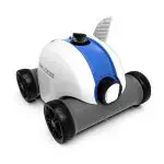
DORADO™
AUTOMATIC POOL CLEANER
INSTALLATION AND USER’S GUIDE
IMPORTANT SAFETY INSTRUCTIONS READ AND FOLLOW ALL INSTRUCTIONS SAVE THESE INSTRUCTIONS
IMPORTANT WARNING AND SAFETY INSTRUCTIONS
![]() Important Notice:
Important Notice:
Attention Installer: This guide contains important information about the installation, operation, and safe use of this product. This information should be given to the owner and/or operator of this equipment after the installation of the pool cleaner.
Attention User: This manual contains important information that will help you in operating and maintaining this pool cleaner. Please retain it for future reference. Consult Pentair with any questions regarding this equipment.
 WARNING: Before installing this product, read and follow all warning notices and instructions which are included. Failure to follow safety warnings and instructions can result in severe injury, death, or property damage. Call (800) 831-7133 for additional free copies of these instructions.
Consumer Information and Safety
This pool cleaner is designed and manufactured to provide many years of safe and reliable service when installed, operated, and maintained according to the information in this manual. Throughout the manual, safety warnings and cautions are identified by the “ ” symbol. Be sure to read and comply with all of the warnings and cautions.
WARNING: HAZARDOUS SUCTION.
![]() Do not play with cleaner or hose or apply to body. Can trap and tear hair or body parts. The hose can trip or entangle swimmers which could result in drowning.
Do not play with cleaner or hose or apply to body. Can trap and tear hair or body parts. The hose can trip or entangle swimmers which could result in drowning.
WARNING:
![]() SUCTION ENTRAPMENT, INJURY, AND DROWNING HAZARD. If your pool has a dedicated suction port (“vac port”) for vacuuming or for an automatic pool cleaner, it must be covered when not in use. A spring-loaded safety cover (a “vac port fitting”) is included with your cleaner. Install it on the suction port to prevent entrapment and injury. If the cover provided does not fit, purchase one that does from your local pool store and install it instead. The cover should conform to IAPMO SPS4-99A.
SUCTION ENTRAPMENT, INJURY, AND DROWNING HAZARD. If your pool has a dedicated suction port (“vac port”) for vacuuming or for an automatic pool cleaner, it must be covered when not in use. A spring-loaded safety cover (a “vac port fitting”) is included with your cleaner. Install it on the suction port to prevent entrapment and injury. If the cover provided does not fit, purchase one that does from your local pool store and install it instead. The cover should conform to IAPMO SPS4-99A.
WARNING: Stop pump before attempting to clean unit. Do not allow swimmers in the pool while the pool cleaner is operating.
WARNING: To reduce the risk of injury, do not let children use or play with the pool cleaner.
WARNING: Do not allow swimmers in the pool while the pool cleaner is operating. The hose can trip or entangle swimmers which could result in drowning.
CAUTION: Moving parts may injure hands or fingers. Stop pump before attempting to clean out pool cleaner head.
General Installation Information
Pre-Installation Check List
Before installing your cleaner, review and understand all warnings and safety information in this guide. Failure to follow these instructions or improper installation of the cleaner can result in damage to the pool finish or the vinyl liner, Most cleaners are not designed to traverse from floor to wall when the pool cove is 90%. There may be other structures installed in the pool that the cleaner cannot navigate, BE AWARE and supervise the cleaner during unique conditions. Pentair Water Pool and Spa, Inc. disclaim any liability for repairs or replacement to any of these structures or components of the customer’s pool.
Before installing the cleaner in a vinyl liner pool:
Check the liner closely for signs of deterioration or damage from age, chemicals, pool wall damage, etc. If any damage is found, have a qualified pool professional make all the necessary repairs. Also, if there are stones, roots, etc., under the liner, remove them before installing the cleaner.
Before installing the cleaner in a gunite pool or a pool that is partially or completely tiled:
Make sure the pool finish is in proper condition as staining, etching, cracking or delaminating may worsen.
Repair loose tiles and tighten any loose light rings.
Before installing the cleaner, clean your filter system:
Make sure you have cleaned the filter, including backwashing, rinsing, and emptying all baskets. A clean system is necessary for proper cleaner operation and coverage.
Before installing the cleaner, understand cleaner coverage:
The cleaner is designed to rid your pool of debris in approximately 4-6 hours. Less time could be needed, depending on the pool size. The cleaner was not designed to automatically clean steps or swim outs or to work under a solar cover. The cleaner may get stuck in these areas which can result in damage to the pool finish or vinyl liner. Pentair Water Pool and Spa, Inc. disclaim any liability for repairs or replacement to any of these structures or components of the consumer’s pool. It was also not designed to do the initial cleanup for a new pool or when opening your pool for the season.
AFTER installing the cleaner, make sure the cleaner is operating correctly:
The cleaner may need some minor adjustments to make sure it is operating properly so there is no damage to the pool finish. Certain vinyl liner patterns are particularly susceptible to surface wear, pattern removal, ink rubbing off, or serious scratches to the pattern caused by objects coming into contact with the vinyl surface, including automatic pool cleaners. Pentair Water Pool and Spa, Inc. is not responsible for any pattern removal, abrasions, or markings on vinyl liners. Periodically inspect the cleaner components and the cleaner performance to ensure it is operating as designed. Replace and/or repair any worn or damaged components. Failure to follow instructions or improper installation of the cleaner may result in damage to the cleaner, pool finish, or vinyl liner.
Warnings and safety instructions for Pentair Water Pool and Spa Pumps and other related products are available at: http://www.pentairpool.com/pool-owner/safety-warnings/ or call (800) 831-7133 for additional free copies of these instructions.
Please refer to http://www.pentairpool.com/pool-owner/safetywarnings/ for warning and safety instructions related to this product.
Disclaimer of Liability About your Pool and Cleaner
There is a multitude of factors that contribute to the life of your pool. The pool cleaner is a very passive product that will have no impact on pool life.
Please be aware that over time, deterioration, discoloration, and brittleness of any pool finish can be caused separately by, or in combination with, age, an imbalance in pool water chemistry, improper installation, and other factors. Pressure side pool cleaners will not remove or cause wear on “good” pool plaster. In fact, the opposite is true–pool plaster will eventually cause wear on the cleaner.
The same situation holds true for vinyl-lined in-ground swimming pools because vinyl liners are also affected by the environment and factors such as pool water chemistry, sunlight, and the pool’s surroundings. Therefore over time, vinyl can become brittle and weak. In addition, vinyl-lined pools are affected by the workmanship, composition, and installation of the liner and the workmanship and quality of construction of the supporting walls and pool base. These are all factors that can contribute to liver failure. The existence of any of these types of conditions in your pool is not caused by the use or operation of the pool cleaner. The manufacturer disclaims any liability for repairs or replacement to any of these structures or components of the customer’s pool.
The pool owner must assume all responsibility for the condition and maintenance of the pool’s surface, water, and deck.
Before the cleaner is installed, please take a moment to record the serial number. This number is located on your warranty card and on the back of the cleaner near the rear jets. You will be asked for this number when you contact our Technical Support Department.
SERIAL #__________________________________
SAVE THESE INSTRUCTIONS
POOL PREPARATION
Congratulations on your purchase of the Dorado™ Automatic Pool Cleaner! Nothing quite compares to the Dorado’s ability to make dirt disappear. With its 15” cleaning path and unique bristle drive, your Dorado automatic pool cleaner will deliver fast, complete coverage of your pool. First, however, you’ll have to install the cleaner and perhaps make some minor adjustments.
This manual covers the steps needed to install, adjust and maintain your new cleaner.
Preparing Your Pool
Before you assemble and install your cleaner, you should make sure that your pool is clean and free of algae. If necessary, make the following preparations before proceeding.
- Chemically balance the pool water
- Brush the pool and let the debris settle
- Hand vacuum the pool thoroughly
- Clean the filter and pump strainer basket (Figure 1)
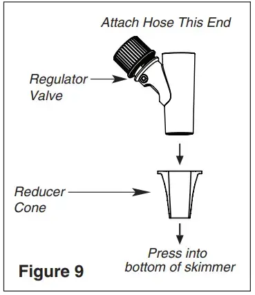
Cleaner Components
Remove the cleaner and all of its parts from the box and check to make sure that all components were included (Figure 2).
- Cleaner
- Swivel Assembly
- Handle Adapter
- Reducer Cone
- Leader Hose: One 40” (1.02 m) length
- Hose: Eleven 40” (1.02 m) lengths
- Vacuum Regulator
- Regulator Cap
- Vacuum Port Fitting
- Flow Gauge

ASSEMBLING THE CLEANER
Attaching Swivel Assembly to Cleaner Head
Installing the swivel assembly is a snap. Just insert it into the Dorado™ Automatic
Pool Cleaner body and give it a quarter-turn (Figure 3).
If you attach an unadapted handle to the swivel for manual vacuuming, be sure it is the special, floating unadapted handle provided with the cleaner (Replacement Part No. GW9019). The use of a different unadapted handle will hinder the cleaner’s performance.
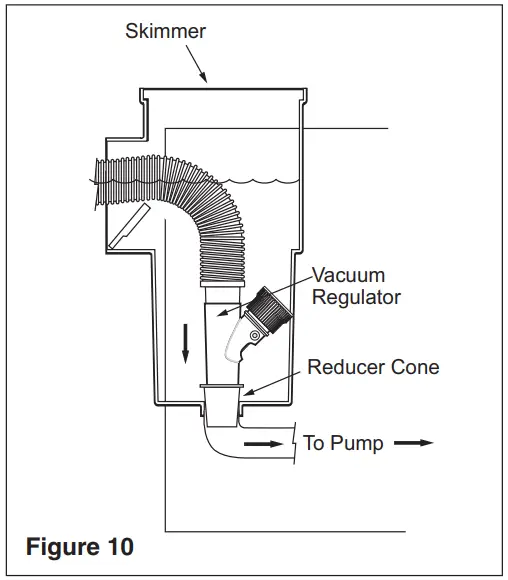
Assembling the Hose
The cleaner includes twelve sections of hose, each 40 in. (1.02 m) in length (Figure 4). Do not cut the hose lengths. You will need to connect these 40” sections of hose to create a combined hose length that is at least 4 ft. (1.22 m) longer than the distance from your suction source (whether skimmer or dedicated suction line) to the farthest point in the pool (Figure 5). Connect the hoses by twisting and pushing the female ends onto the male ends after wetting the ends in the pool (Figure 6).
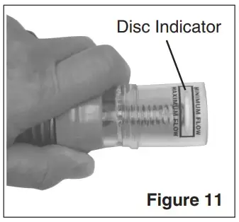
A special “leader” hose section is designed to connect to the cleaner’s swivel assembly and therefore has a larger hose cuff than the other hose lengths (Figures 7 and 8). Failure to use this leader hose section to attach the hose to the cleaner’s swivel assembly will hinder your cleaner’s performance. If the additional hose is needed, use only hoses from your Pentair Water Pool and Spa dealer (order replacement part No. 41200-0131). The use of another manufacturer’s hose will hinder cleaner coverage.
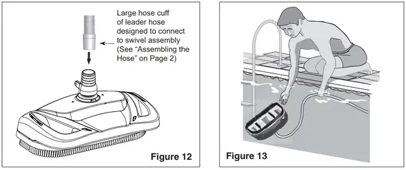
INSTALLATION
This section describes how to install the Dorado™ Automatic Pool Cleaner. The cleaner is designed to work in a wide variety of swimming pools. Both the standard in-skimmer installation and optional vac port installation are covered below. If your pool configuration is unlike any of the examples, contact your Pentair Water Pool and Spa dealer for assistance, or call Pentair at 1-800-831-7133.
Standard Installation
For pools with one skimmer, using the vacuum regulator
The manufacturer recommends the Standard Installation through the pool’s skimmer (Figure 8). The advantage of this installation is its use of the vacuum regulator to balance the water flow between the skimmer and the pool cleaner. The vacuum regulator can be adjusted to changes in the amount of water flow to provide the cleaner with the power necessary to ensure proper cleaning performance, and the manufacturer strongly recommends its use for maximum safety and performance.
- Turn the pool pump off
- Adjust valves for vacuuming
Adjust the pump valves (if your system has valves) to direct all suction to the skimmer. Close the main drain and all suction lines, except the line from the skimmer to which the cleaner will be connected. - Remove the skimmer basket from the skimmer
- Install vacuum regulator

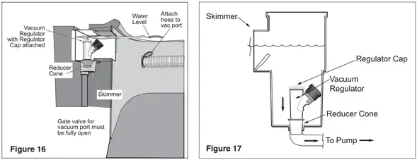 WARNING:Use the vacuum regulator in conjunction with your pool cleaner system at all times. The vacuum regulator has an adjustment knob If suction is too high, the knob is turned counterclockwise to decrease the suction. If the suction is too low, the knob is turned clockwise to increase the suction.
The vacuum regulator must be installed in conjunction with the reducer cone (Figure 9). The reducer cone is required to make most skimmer connections. It will keep the hose and vacuum regulator in place once the filter system is stopped.
To install the vacuum regulator, insert the vacuum regulator and reducer cone in the skimmer. Attach the end of the hose to the regulator (Figure 10).
Make sure the vacuum regulator is submerged at all times. If not, the pump will suck air through the vacuum regulator and lose its prime. This could damage the pump.
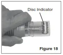
- Check Flow
With the main drain closed, and one end of the hose attached to the regulator installed in the skimmer, insert the flow gauge into the other end of the hose. Keep the hose and flow gauge underwater. Turn on the pump. With the pump running, adjust the vacuum regulator (in your skimmer) until the indicator on the flow gauge is between the minimum and maximum flow (Figure 11). Remove the flow gauge and proceed to step 6.
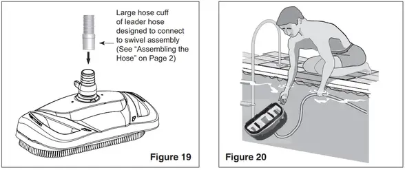
- Connect Hose to the Cleaner’s Swivel Assembly
Connect the large hose cuff (Figure 12) of the leader hose to the swivel assembly on the Dorado™ Automatic Pool Cleaner head (Figure 12). Push the cleaner into the pool and let it sink to the bottom (Figure 13).
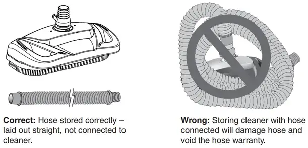
- Turn the pool pump on
After completing the installation, turn the pool pump on and allow it to run for a couple of minutes to ensure that all air cycles out of the system.
Optional Installation
Vac Port Installation with Vacuum Regulator in Skimmer
If your pool has a vac port (Figure 14), you can install Dorado™ Automatic Pool Cleaner using the Optional Installation.
- Turn the pool pump off
- Adjust valves for vacuuming
Adjust the pump valves (if your system has valves) to direct all suction to the dedicated vacuum line and the skimmer. Close the main drain and all suction lines, except the line from the dedicated vacuum line to which the cleaner will be connected, and the skimmer where the vacuum regulator will be installed. - Install vac port door fitting.
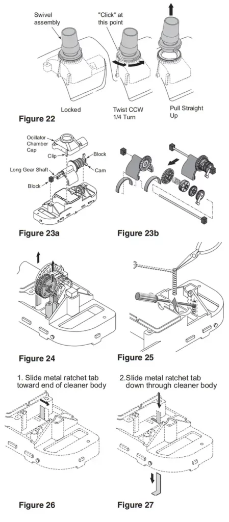
 WARNING: Suction entrapment, injury, and drowning hazard. If your pool has a dedicated suction port (“vac port”) for vacuuming or for an automatic pool cleaner, it must be covered when not in use.
A spring-loaded safety cover (the “vac port fitting”) is included with this pool cleaner (Figure 15). Install it on the dedicated vacuum line to prevent entrapment and injury. For details please refer to the Vac Port Instruction sheet included with your vac port fitting. To install the included vac port fitting:
1. Screw the vac port fitting into the dedicated vacuum line opening.
2. Orient the vac port fitting so the arrow on the door points up.
3. Secure the cover by tightening the Allen screw below the door, into the dedicated vacuum line fitting. - Remove the skimmer basket from the skimmer
- Install vacuum regulator.
WARNING: Hazardous suction. Can cause entrapment with severe personal injury or drowning.
To install the vacuum regulator, insert the vacuum regulator and reducer cone in the skimmer (Figure 16).
To prevent water from flowing through the top of the vacuum regulator, attach the regulator cap to the vacuum regulator (Figure 17). Attach the end of the hose to the vac port fitting installed in the dedicated vacuum line (Figure 16).
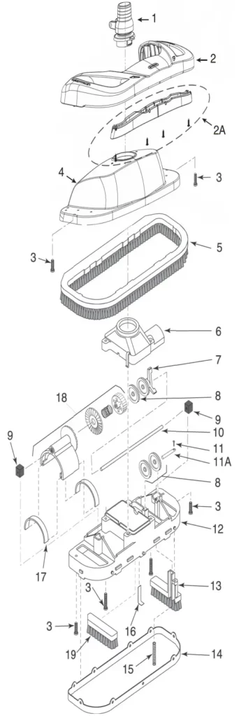
- Check Flow
With the main drain closed, and one end of the hose attached to the vac port fitting installed in the dedicated vacuum line, insert the flow gauge into the other end of the hose. Keep the hose and flow gauge underwater. Turn on the pump. With the pump running, adjust the vacuum regulator (in your skimmer) until the indicator on the flow gauge is between the minimum and maximum flow (Figure 18). Remove the flow gauge and proceed to step 7.
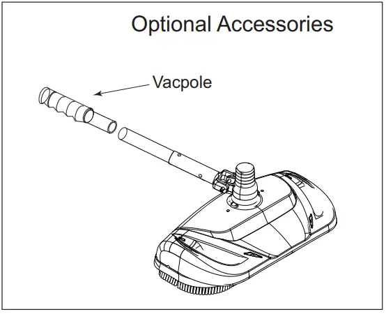
- Connect Hose to the Cleaner’s Swivel Assembly
Connect the large hose cuff (Figure 19) of the leader hose to the swivel assembly on the Dorado™ Automatic Pool Cleaner head. Push the cleaner into the pool and let it sink to the bottom (Figure 20).

- Turn the pool pump on
After completing the installation, turn the pool pump on and allow it to run for a couple of minutes to ensure that all air cycles out of the system.
OPERATION
This section contains information describing the movement and operation of your Dorado™ Automatic Pool Cleaner, as well as tips for “fine-tuning” your pool’s valves and connections to optimize the cleaner’s cleaning ability.
Cleaner Operation and Movement
Clicking sound
This is the sound of the oscillator moving back and forth in the oscillator chamber. The best speed for it is about 500 oscillations per minute. The vibration created by the oscillator moves the bristles and the cleaner. If the oscillator is running too fast, the cleaner will have a tendency to climb up the pool wall past the waterline, or “walk out of the pool” and suck air. Reduce the speed by adjusting the vacuum regulator in the skimmer.
Movement around the pool
Random motion – The cleaner will visit most spots in the pool within a six (6) hour period. It is not specifically programmed, and cannot see the dirt you are seeing. It is a random motion pattern.
The cleaner was designed to spend most of its time in the deep end, where most of the floor and wall area exists. During a six (6) hour period, the cleaner will visit the shallow end a few times.
Rotating motion – The cleaner will rise up on one side and pivot a few times per minute. This is normal and provides the following:
- Allows leaves that are being pushed or dragged along to be sucked up into the vacuum chamber.
- Allows the cleaner to:
Change direction
Get out of corners
Get away from ladders
Submerge below pool water level
Get off of domed main drain covers
Picks up “big stuff”
The cleaner will pick up some debris so large that it may jam. Simply stop the pump and remove the debris from the oscillator, or the swivel assembly.
Fine-tuning Valves and Connections
WARNING: Pool pump suction is hazardous and can cause entrapment with severe personal injury or drowning. Use a vacuum regulator (see instructions below) in the pool cleaner system at all times.
NOTICE: Each pool’s hydraulic system and vacuum connections are different. Be sure you have installed the vacuum regulator before you “fine-tune” the system. This not only regulates vacuum but also acts as a safety device.
WARNING: Suction entrapment, injury, and drowning hazard. If your pool has a dedicated suction port (“vac port”) for vacuuming or for an automatic pool cleaner, it must be covered when not in use. A spring-loaded safety cover (the “Vac Port Fitting”) is included with this pool cleaner. Install it on the vac port to prevent entrapment and injury. For details please refer to the Vac Port Fitting instruction sheet included with your cleaner.
For the novice pool owner for whom pool vacuuming is a new experience, please read all of the following points, installation instructions, and troubleshooting guide carefully.
Please note the following:
- “Vacuum” and “suction” are two words meaning the same thing.
- “Dedicated suction line”, “vac port”, and “vac fitting” are different terms for a hole in the sidewall of a pool; this hole is connected to the pump suction and is dedicated to vacuuming.
- Some pools do not have a vac port. If your pool does have one, please read the “Suction Entrapment” warning above.
For the seasoned pool owner: The Dorado™ Automatic Pool Cleaner connection and vacuum adjustments can be similar to using your manual pool vacuum. Please read on.
Valves (Pump, Skimmer, and Main Drain) and Vacuum Adjustments
You may need to spend some time adjusting the skimmer and main drain valves in order to obtain the best vacuum setting for good cleaner operation. Once you have found the correct valve settings for the best operation, we suggest you mark the valves to ensure repeated success.
At first, set valves to give maximum vacuum to the skimmer or vac fitting you have elected to use.
Too Much Vacuum?
You have too much vacuum if the cleaner climbs up the pool wall past the water line to the point that the cleaner sucks air and the pump loses prime. Frequent loss of prime will damage the pump. To correct this, adjust the regulator by turning the adjustment knob counterclockwise. This will decrease the suction. If the cleaner still climbs out and sucks
air, open the main drain valve slightly.
Not Enough Vacuum?
You don’t have enough vacuum if the cleaner moves sluggishly or not at all. Be sure the filter system is clean and the regulator and all valves are adjusted to give you maximum vacuum. If the cleaner is still not moving, your pump may not be strong enough to operate the cleaner. Please refer to “Troubleshooting” on Page 17.
In-Line Leaf Canisters
If your pool is exposed to large quantities of leaves, we suggest purchasing and installing an in-line leaf canister (part no. R211084K). A leaf canister will provide more debris-loading capacity and also provides a water by-pass when the canister is full. It is very important that the pump not starve for water!
Skimmer Connection
For pools that have large quantities of “big stuff” to pick up, we suggest using the bottom of the skimmer connection in conjunction with an in-line leaf canister (part no. R211084K). A leaf canister will provide more debris-loading capacity and also provides a water by-pass when the canister is full. It is very important that the pump not starve for water!
Skimmer Vac Plates
Some pool owners connect the hose to a skimmer vac plate, which allows the skimmer basket to remain in the skimmer. If this method is used, empty the basket frequently. Also, make sure that the vacuum regulator provided is completely submerged so that it will not suck air and damage the pump.
Skimmer Vac Plate Vacuum Control Adjusters
Some pool owners use one of a variety of manufacturers’ skimmer vac plates. Some have a vacuum control adjuster, and some do not. The adjuster could be a screw-type, a spring-loaded apparatus, or a dial design. For those vac plates with adjusters, it is important to adjust them when fine-tuning the vacuum for the Dorado™ Automatic Pool
Cleaner.
MAINTENANCE
This section describes the service and maintenance of the Dorado™ Automatic Pool Cleaner.
WARNING: Hazardous suction. Stop pump before attempting to clean pool cleaner.
- Keep the skimmer basket and pump strainer basket clean and free of debris.
- If cleaner jams with large debris (leaves, sticks, etc.), try cleaning debris first from the bottom of the unit. If this doesn’t clear the unit, remove the top swivel assembly (turn 1/4 turn) and clear the debris from the top.
- Remove the pool cleaner from the pool before super chlorinating (shocking) or chemical balancing. Wait at least four hours after the chemical procedure before reinstalling the cleaner.
- Make sure that the cleaner’s brush bristles don’t become deformed during storage. Store the unit so that it doesn’t sit on the bristles and so that nothing compresses them.
- Do not coil the hose. Remove the hose from the cleaner when removing the cleaner from the pool. Store the hose flat and straight.
- Periodically examine bristles and vacuum skirts for wear or distortion. Replace if necessary. See “Reassembly”, Page 17.
- Don’t store the cleaner with the hose connected to the cleaner body or with the hose coiled. To do so will cause the hose to take a set or kink over a period of time. When reinstalled in the pool, the hose will tend to stay coiled and will cause the cleaner to malfunction.
- If the hose has taken a set, uncoil it as far as possible without damaging it and lay it out in the sun for several hours to straighten itself. Once it has relaxed and straightened out, store it laid out flat and straight (no coiling).
- Make sure the lift brush is retracted during storage. If the lift brush is down during storage and the cleaner rests on it, the brush bristles will collapse over time and the cleaner will no longer turn during operation as it was designed to do.
Hose Storage
Disassembly
- Remove swivel assembly (Figure 22) from the top of the Dorado™ Automatic Pool Cleaner by turning it 1/4-turn counterclockwise and pulling it straight up on it.
- Turn the cleaner upside down. Remove 6 screws and remove the lower body assembly from the shroud.
- Turn lower body assembly right side up. Unsnap the 2 clips on the oscillator chamber cap (Figure 23a); lift it off.
- Pull the long gear shaft straight up (Figure 23a) by the blocks on the ends of the shaft. Hold the seals in the oscillator and the blocks on the shaft. The cam may interfere with the shaft mounting post; if so, turn it slightly on the shaft until it clears the post. The shaft assembly can now be disassembled (Figure 23b).
- Slide the long gear shaft out of the oscillator (with gears, complete); make sure that you don’t lose the seals out of the oscillator which may fall out at this point (Figure 23b).
5A. Oscillator seals are replaceable.
5B. Ratchet gear set and long shaft are replaceable as a unit. - Remove the set screw, short gear shaft, and gears (Figure 24); be sure to keep the gears on.
- With a small screwdriver (such as a jeweler’s screwdriver), a pencil, or a pen point, depress and remove the coil spring from the lift brush mounting post (Figure 25). Replace the brush and the spring if necessary.
- The metal ratchet tab slides out of its slot sideways; replace it by removing the center brushes and sliding in a new ratchet tab until it is flush with the edge of the plastic holder (Figures 26 and 27). Replace the center brushes.
- The brush ring pops out of the cleaner body for easy replacement.
- If you need to replace the bumper, turn the shroud and bumper assembly upside down and remove the two screws holding the bumper to the shroud.
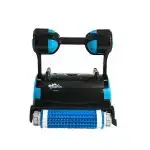
Reassembly
- Put both white seals in the oscillator; hold them in place.
- Install the oscillator on the long gear shaft. Install the ratchet gear on the shaft so that the teeth engage the ratchet on the oscillator. Install the spring, ratchet drum, pinion gear (large gear first), and cam (gear end first) on the shaft (see Figure 28). Hold the gears on the shaft while installing them, and compress the clutch spring to allow the assembly to slip into place between the posts (see Figure 28).
- Install the long gear shaft and end blocks in the cleaning head with the large arm of the cam down (see Figure 29).
- Reinstall the short gear shaft, set screw, and two gears (see Figure 30); the small pinion gears and the shaft set screw go on the side toward the end of the cleaner – away from the oscillator box. Make sure that the gears engage the gears on the long gear shaft.
- Install the oscillator chamber cap and clip it in place.
- Install the rubber vacuum skirt on the cleaner with the word ‘OUTSIDE’ showing. Start at the large pin on the back of the cleaner head (see Figure 31) and work around the cleaner. Make sure the skirt is flush against the stop strips on the cleaner head (see Figure 32).
- Turn the cleaner over. If you removed the bumper and brush ring, replace them now.
- Install the lower body assembly in the shroud. Fasten the cleaning head in place with 6 screws (2 long, 2 short – see Figure 33).
NOTE: Make sure that you do not dislodge the rubber vac skirt while inserting the lower body assembly past the brush ring.
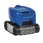
Illustrated Parts List


| Item No. | Description | Part No. |
| 1 | Swivel Assembly | GW9012 |
| 2 | Bumper | 360152 |
| 2A | Bumper Insert Kit (Incl. 2 Bumper Inserts and 4 Bumper Insert Screws) | 360154 |
| 3 | Screw Kit (6 short, 2 long) | GW9504 |
| 4 | Shroud | 360153 |
| 5 | Brush Ring | GW9505 |
| 6 | Oscillator Chamber Cap | GW9506 |
| 7 | Cam Kit (2 & 3 Leg Cams) | GW9507 |
| 8 | Idler Gear Kit (Incl. 3 Gears) | GW9509 |
| 9 | Block Kit (Incl. 2 Blocks) | GW9512 |
| 10 | Long Gear Shaft (Stainless Steel) | GW9513 |
| 11 | Set Screw #4 Self Tapping## | |
| 11A | Shaft Kit, Stainless Steel (Incl. Set Screw) | GW9536 |
| 12 | Lower Body* | GW9535 |
| 13 | Lift Brush | GW9517 |
| 14 | Vacuum Skirt | GW9508 |
| 15 | Lift Brush Spring | GW9522 |
| 16 | Ratchet Tab (Stainless Steel) | GW9523 |
| 17 | Oscillator Seal Kit (Incl. 2 Seals) | GW9004 |
| 18 | Oscillator Assembly Kit (Incl. Key #17) (Ratchet Assembly not sold separately) | GW9503 |
| 19 | Center Brush Kit (Set of 2) | GW9013 |
| • | Hose Kit, 12 sections, every 4 ft in length | 41200-0131 |
| • | Vacuum Regulator | 41200-0200 |
| • | Vacuum Regulator Cap | 41200-0211 |
| • | Reducer Cone | GW9015 |
| • | Unidad Handle | GW9019 |
| • | Vac Port Fitting | GW9530 |
| • | Flow gauge | 41200-0210 |
(•) – Note Shown
(*) – Includes Item Nos. 6, 11A, 13, 15, 16, two idler gears, and a 2-arm cam
(##) – Not available separately
DORADO™ Automatic Pool Cleaner Installation and User’s Guide
TROUBLESHOOTING
| SITUATION | SOLUTIONS: |
| The cleaner does not move Oscillator is very slow | 1. Backwash and/or clean filter. Empty all baskets. This should help your cleaner attain the desired oscillation. Correct oscillator speed can be determined by using the flow gauge provided with the cleaner (see page 4). 2. Clear all debris from the oscillator chamber, hose, or vac plate by-pass (if you have one). 3. Repair all sources of vacuum leaks (cracked vac plate, vac plate or reducer cone not seated properly, cracked hose, vac regulator adjusted too loosely). 4. Adjust valves to give maximum vacuum to the vacuum port or skimmer to which you are attaching the cleaner hose. Reduce or shut off other skimmers and the main (floor) drain.NOTE: Each pool’s hydraulic system is different. It may require some adjustments to the skimmer and main valves before you achieve the vacuum setting required for the best cleaner operation. Once determined, mark the valves at that position to ensure repeated success. 5. Filtration system (pump) does not develop enough vacuum. Consult your pool service professional. |
| Cleaner climbs past the waterline of the pool causing the pump to lose prime (suck air) | 1. Oscillator is running too fast. Make sure the vacuum regulator is installed and adjusted. 2. If step 1 does not solve the problem, slightly open the main drain valve until the cleaner no longer climbs out of the pool. |
| Cleaner coverage not as expected | 1. A clean filter system will help the cleaner to move much faster. Also, be sure to clean all baskets. 2. Vinyl liner pools with a deep end hopper will require 6-8 hours to clean. During this time the cleaner should make at least 4 trips to the shallow end. If not, call Customer Service at 1-800-831-7133. 3. Examine the lift brush mechanism as the cleaner is operating. To do this, you will have to turn the cleaner over while it is running and submerged. If the lift brush does not move to the “down” position within 2 minutes, call Customer Service at 1-800-831-7133. 4. The cleaner was not designed to work under solar covers. If you have a solar cover, only minimal coverage can be expected. 5. Any cleaner might miss a spot. Your cleaner has been designed to accommodate the attachment of a vac-pole (telephone) by use of the handle in the accessory bag. Attach pole for spot cleanups, steps, and swim outs. |
| Cleaner “stuck” in one spot (more than 15 mins) | 1. Examine the lift brush mechanism as the cleaner is operating. To do this, you will have to turn the cleaner over while it is running and submerged. If the lift brush does not move to the “down” position within 2 minutes or less, call Customer Service at 1-800-831-7133. |
| Steps and “swim-outs” are not clean | 1. This cleaner was not designed to clean these areas. Use the handy telephone attachment, connect the pole, and clean missed areas. |
| The cleaner flips on its back when the pump stops | 1. This is normal with some filter systems that develop a surge of back pressure when the system shuts off. The cleaner will right itself when the system is restarted. |
| Hose comes loose when the pump stops | 1. Use the reducer cone when connecting to the skimmer or vac port. |
| Cleaner hovers in one area with hose fully extended | 1. Hose might be too short. The desired length can be measured from the point where the hose is connected, to the furthest point of the pool, plus a minimum of an additional 4’. If needed, purchase an extension hose from your local dealer. Do not cut the extension hose – use its full length even if it is a little long. |
| Hose keeps coiling up | 1. For best results, when the hose is not in use, store it uncoiled, flat, and straight. 2. Lay the hose out flat and straight in the sunlight for a few hours prior to use. |
| Cleaner avoids shallow end of the pool | 1. This could be caused by a buoyancy issue. Add a hose weight (P/N 41201-0238; sold separately) to the cleaner hose. |
CUSTOMER SERVICE/TECHNICAL SUPPORT
If you have questions about ordering Pentair Aquatic Systems replacement parts, and pool products, please use the following contact information:
Customer Service (8 A.M. to 4:30 P.M. — Eastern and Pacific Times)
Phone: (800) 831-7133
Fax: (800) 284-4151
Web site
visit: www.pentairpool.com or www.staritepool.com to find more information about Pentair products.
Technical Support
Sanford, North Carolina (8 A.M. to 4:30 P.M. ET)
Phone: (919) 566-8000
Fax: (919) 566-8920
Moorpark, California (8 A.M. to 4:30 P.M. PT)
Phone: (805) 553-5000 (Ext. 5591)
Fax: (805) 553-5515

1620 HAWKINS AVE., SANFORD, NC 27330 • (919) 566-8000
10951 WEST LOS ANGELES AVE., MOORPARK, CA 93021 • (805) 553-5000
WWW.PENTAIRPOOL.COM
All Pentair trademarks and logos are owned by Pentair or one of its global affiliates. Pentair Aquatic Systems and Dorado™ are trademarks and/or registered trademarks of Pentair Water Pool and Spa, Inc. and/or its affiliated companies in the United States and/ or other countries. Unless expressly noted, names and brands of third parties that may be used in this document are not used to indicate any affiliation or endorsement between the owners of these names and brands and Pentair Water Pool and Spa, Inc. Those names and brands may be the trademarks or registered trademarks of those third parties. Because we are continuously improving our products and services, Pentair reserves the right to change specifications without prior notice. Pentair is an equal opportunity employer.
© 2016 Pentair Water Pool and Spa, Inc. All rights reserved. This document is subject to change without notice.
]]>