BEFORE YOU BEGIN
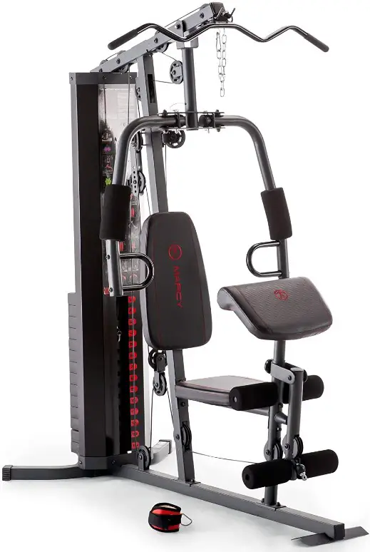
Thank you for selecting the MARCY HOME GYM MWM-989 by IMPEX® INC. For your safety and benefit, read this manual carefully before using the equipment. As a manufacturer, we are committed to provide you complete customer satisfaction. If you have any questions, or find there are missing or damaged parts, we guarantee you complete satisfaction through direct assistance from our factory. To avoid unnecessary delays, please call our TOLL-FREE customer service number. Our Customer Service Agents will provide immediate assistance to you.
IMPORTANT SAFETY NOTICE
PORTANT SAFETY NOTICE
This exercise equipment is built for optimum safety. However, certain precautions apply whenever you operate a piece of exercise equipment. Be sure to read the entire manual before you assemble or operate your equipment. In particular, note the following safety precautions:
- Keep children and pets away from the equipment at all times. DO NOT leave children unattended in the same room with the equipment.
- Only one person at a time should use the equipment.
- If the user experiences dizziness, nausea, chest pain, or any other abnormal symptoms STOP the workout at once. CONSULT A PHYSICIAN IMMEDIATELY.
- Position the equipment on a clear, leveled surface. DO NOT use the equipment near water or outdoors.
- Keep hands away from all moving parts.
- Always wear appropriate workout clothing when exercising. DO NOT wear robes or other clothing that could become caught in the equipment. Running or aerobic shoes are also required when using the equipment.
- Use the equipment only for its intended use as described in this manual. DO NOT use attachments not recommended by the manufacturer.
- Do not place any sharp object around the equipment.
- Disabled person should not use the equipment.
- Before using the equipment to exercise, always do stretching exercises to properly warm up.
- Never operate the equipment if the equipment is not functioning properly.
- A spotter is recommended during exercise.
- This equipment is designed and intended for home and consumer use only, not for commercial use.
WARNING: BEFORE BEGINNING ANY EXERCISE PROGRAM, CONSULT YOUR PHYSICIAN. THIS IS ESPECIALLY IMPORTANT FOR INDIVIDUALS OVER THE AGE OF 35 OR PERSONS WITH PRE-EXISTING HEALTH PROBLEMS. READ ALL INSTRUCTIONS BEFORE USING ANY FITNESS EQUIPMENT. IMPEX INC. ASSUMES NO RESPONSIBILITY FOR PERSONAL INJURY OR PROPERTY DAMAGE SUSTAINED BY OR THROUGH THE USE OF THIS PRODUCT.
SAVE THESE INSTRUCTIONS.
EXERCISE GUIDELINES
Building Muscle and Gaining Weight
Unlike aerobic exercise, which emphasizes endurance training, anaerobic exercise focuses on strength training. A gradual weight gain can occur while building the size and strength of muscles. While developing muscle mass, your body adapts to the stress placed upon it. You can modify your diet to include foods such as meat, fish and vegetables. These foods help muscles recover and replenish important nutrients after a strenuous workout.
Muscle Strength and Endurance
To achieve the greatest benefit from exercise, it is important to develop an exercise program that allows you to work all of the major muscle groups equally.
To increase muscles strength; follow this principle:
Increasing resistance and maintaining the number of repetitions of an exercise results in increased muscle strength.
To tone your body, follow the principle: Decreasing resistance plus increasing the number of repetitions of an exercise results in increased body tone.
Once you feel comfortable with an exercise, you can change the resistance, the number of repetitions, or the speed at which you do the exercise. It is not necessary to change all three variables. For example, let’s say that you are training at 50 lb / 22.5 kg and performing the exercise 10 times in 3 minutes. When this becomes too easy, you may decide to move up lifting 60 lb / 27 kg for the same number of repetitions in the same amount of time. Lifting more weights fewer times most often develops muscle strength. To gain both muscle strength and endurance, it is recommended that you perform each exercise 15 to 20 reps per set.
Training Intensity
How hard you begin to train depends on your overall level of fitness. The soreness you experienced can be lessened by decreasing the load you place on your muscles and by performing fewer sets. To avoid injury, you should gradually work into an exercise program and set the load to your individual fitness level. The load should increase as your fitness level increases.
Muscle soreness is common, especially when you first start exercising. If you are painfully sore for a long time, it may be time to change your program. Eventually, your muscle system will become accustomed to the stress and strain placed on it.
Beginning a Strength Building Program
Warming Up
To begin strength training, it is important to stretch and perform light exercise for 5 to 10 minutes.
This helps prepare the body for more strenuous exercise by increasing circulation, raising your body temperature and developing more oxygen to your muscles.
Workout
Each workout to keep in mind that muscle soreness that lasts for a long period in not desirable and may mean that injury has occurred.
Cool Down
At the end of each workout, perform slow stretching exercises for 5 to 10 minutes. Ease into each stretch only going as far as you can. This stage allows your muscles wind down after training.
To provide a total workout program it is also recommended that 2 to 3 days of aerobic exercise is performed in addition to the strength training.
Drinking Water
For the body to function properly, it must be properly hydrated. If you are exercising, you should increase your fluid intake. The reason for this is that the water you take in will leave your system through the sweating mechanism that cools your body during exercise. The water you lose through exercise must be replaced so that the muscles can recover properly.
Rest Day
Although you may not feel like doing it, taking a rest day at least once a week is important because it gives your body a chance to heal itself. Continuously working your muscle will result in over training which will not benefit in the long run.
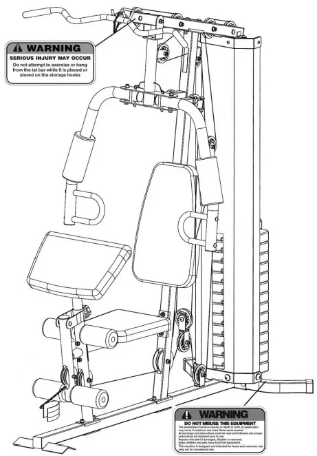
WARNING LABEL PLACEMENT
The warning labels shown here have been placed on the Rear Stabilizer and Upper Frame. If the labels are missing or illegible, please call customer service at 1-800-999 8899 for replacements. Apply the labels in the location shown.
IMPORTANT ASSEMBLY INFORMATION
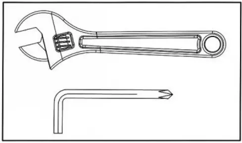
- Tools Required for Assembling the Bench: Two Adjustable Wrenches and Allen Wrenches.
- NOTE: It is strongly recommended that this equipment is assembled by two or more people to avoid possible injury.
- Ensure Carriage Bolts are inserted through the SQUARE holes on components that need to be assembled. Attach washer only to end of the Carriage Bolt.
- Use Allen Bolts or Hex Bolts inserted through the ROUND hole on components that need to be assembled.
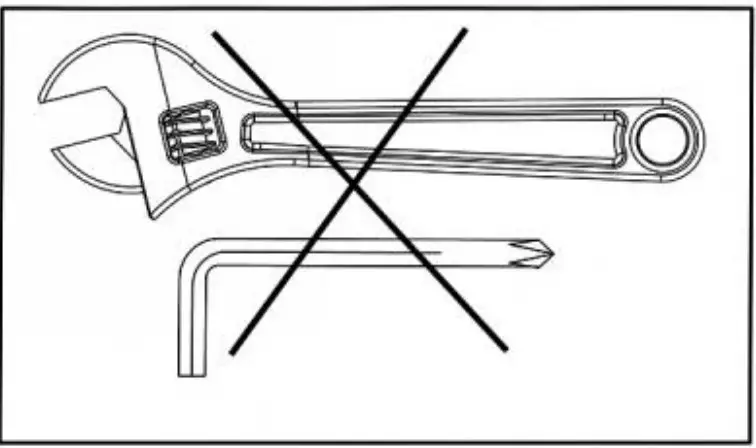
- Always wait until all bolts are assembled onto the bench before tightening the bolts. Do not tighten each bolt right after it is installed.
Fasten Nuts and Bolts
Securely tighten all Nuts and Bolts after all components have been assembled in current and previous steps.
NOTE: Do not over tighten any component with pivoting function.

Make sure all pivoting components are able to move freely.
Do not tighten all Nuts and Bolts in this step.
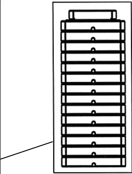
Weight Plate Installation
Slide weight plates onto Guide Rod from top to bottom.
The deep groove on each weight plate needs to face front and downwards.
OPERATION NOTES
Weight Plate Selection
- Use the Weight Selector Pin to select the number of weight plates to exercise.
- Do not insert weight selector pin while the weight stack or top plate is in elevated position.
- Be certain the weight Selector Pin is completely inserted.
- Each Weight Plate weights approximately 10 lb / 4.5 kg.
- Please refer to Weight Resistance Chart page.
- Never use dumbbells or other means to increase the weight resistance. Use only weight plates provided by manufacturer.
- For safety purpose while the equipment is not in use. Insert the Lock Pin into the hole on Guide Rod and use Combination Lock to lock the Pin to prevent the movement of Weight Plates. Please refer to the Combination Lock set up.
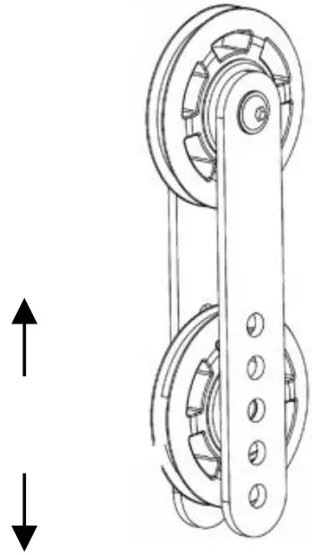
Cable Tension Adjustment
Adjust the tension of the Cable System by moving the position of lower Pulley on the two Double Floating Pulley Brackets.
If the tension is too loose, move the lower pulley up by one hole.
If the tension is too tight, move the lower pulley down by one hole. Lower Pulley
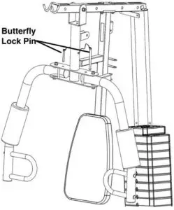
Front Press and Butterfly Exercises
- Insert the Butterfly Lock Pin through the holes on
Front Press Base and Butterfly to lock the Butterfly in position when doing Front Press exercises. - Pull out the Butterfly Lock Pin when doing Butterfly exercises.
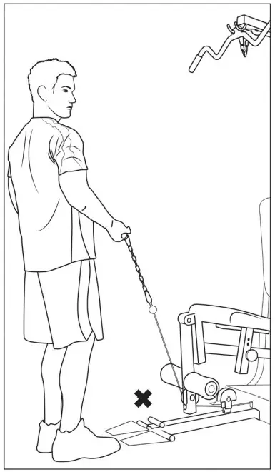
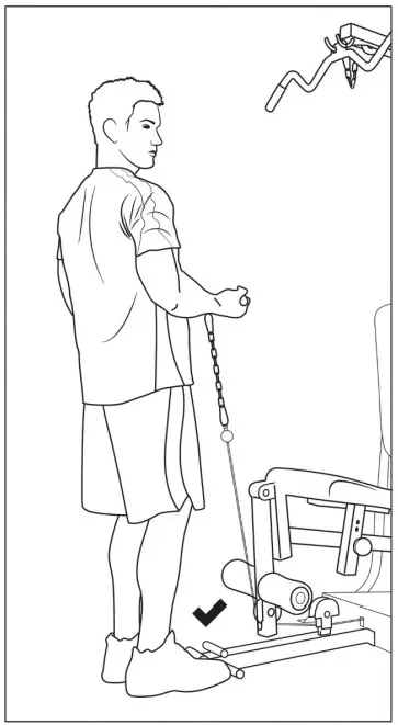
WARNING
Please ensure to step with both feet on the included foot- plate while performing lower pulley exercises to avoid any unwanted movement of the exercise machine.
CARE AND MAINTENANCE
- Lubricate moving parts with WD-40 or light oil periodically.
- Inspect and tighten all parts before using the equipment.
- The equipment can be cleaned using a damp cloth and mild non abrasive detergent.
DO NOT use solvents. - Examine the equipment regularly for signs of damage or wear.
- Replace any defective components immediately and/or keep the equipment out of use until repair.
- Failure to examine regularly may affect the safety level of the equipment.
WEIGHT CAPACITY AND DIMENSION
- Maximum user weight: 300 lbs. (136 kg)
- Assembled Dimension: 68” x 36” x 79” (1727.2mm x 914.4mm x 2007mm)
MWM-989 PARTS LIST
| PART NO | DESCRIPTION | SIZE | SIZE (Metric) | Qty |
| 1 | Upper Frame | 1 | ||
| 2 | Vertical Frame | 1 | ||
| 3 | Base Frame | 1 | ||
| 4 | Rear Stabilizer | 1 | ||
| 5 | Leg Developer Holder | 1 | ||
| 6 | Seat Support | 1 | ||
| 7 | Leg Developer | 1 | ||
| 8 | Front Press Base | 1 | ||
| 9 | Right Butterfly | 1 | ||
| 10 | Left Butterfly | 1 | ||
| 11 | Front Press Handle | 2 | ||
| 12 | Butterfly Cable Bracket | 2 | ||
| 13 | Arm Curl Stand | 1 | ||
| 14 | Swivel Pulley Bracket | 2 | ||
| 15 | Angled Double Floating Pulley Bracket | 1 | ||
| 16 | Weight Stack Cover | 1 | ||
| 17 | Guide Rod | 2 | ||
| 18 | Lat Bar | 1 | ||
| 19 | Selector Rod | 1 | ||
| 20 | Bracket | 1 ¾” x 4 ¾” | 45 mm x 120 mm | 4 |
| 21 | U-shaped Bracket | 2” x 7” | 51 mm x 178 mm | 1 |
| 22 | Lock Knob | 1 | ||
| 23 | Foam Tube | 2 | ||
| 24 | Backrest Board | 1 | ||
| 25 | Seat Pad | 1 | ||
| 26 | Arm Curl Pad | 1 | ||
| 27 | Large Foam Roll | Ø 1⅞”x Ø 8⅝” | Ø 48 mm x 220 mm | 2 |
| 28 | Foam Roll | Ø ⅞” x Ø 7” | Ø 22 mm x 180 mm | 4 |
| 29 | Weight Stack Cover Bracket | 2 | ||
| 30 | Double Floating Pulley Bracket | 2 | ||
| 31 | Rear Stabilizer End Cap | 2 | ||
| 32 | Weight Selector Pin | 1 | ||
| 33 | Chain | 1 | ||
| 34 | C-clip | 2 | ||
| 35 | Selector Stem | 1 | ||
| 36 | Weight Plate | 14 | ||
| 37 | Bushing | Ø1” | Ø 25 mm | 8 |
| 38 | Front Press Axle | 3” | 75 mm | 1 |
| 39 | Butterfly Axle | 2⅝” | 66 mm | 2 |
| 40 | Leg Developer Axle | 1 | ||
| 41 | Weight Plate Rubber Bumper | Ø2⅜”x 1” | Ø 61 mm x 25 mm | 2 |
| 42 | Pulley | 16 | ||
| 43 | Pulley Bushing | Ø ⅞”x ½” | Ø 22 mm x 14 mm | 14 |
| 44 | Rubber Bumper | Ø1⅞”x 2 ½” | Ø 44 mm x 64 mm | 1 |
| 45 | Rubber Bumper | Ø1 ½” x ⅝” | Ø 37 mm x 16 mm | 1 |
| 46 | Butterfly Lock Pin | 2 | ||
| 47 | Ankle Strap | 1 | ||
| 48 | Upper Cable | 116” | 2960 mm | 1 |
| 49 | Butterfly Cable | 91” | 2330 mm | 1 |
| 50 | Lower Cable | 134” | 3420 mm | 1 |
| 51 | Cone-shaped End Cap | Ø1” | Ø 25 mm | 1 |
| 52 | End Cap | 2” x 2” | 50 mm | 3 |
| 53 | End Cap | Ø 2” | Ø 50 mm | 7 |
| 54 | End Cap | Ø1” | Ø 25 mm | 4 |
| 55 | Carriage Bolt | M10 x 2 ¾” | M10 x 70 mm | 10 |
| 56 | Allen Bolt | M10 x 2 ¾” | M10 x 70 mm | 9 |
| 57 | Allen Bolt | M10 x 2 ½” | M10 x 65 mm | 2 |
| 58 | Allen Bolt | M10 x 2” | M10 x 50 mm | 2 |
| 59 | Allen Bolt | M10 x 1 ¾” | M10 x 45 mm | 9 |
| 60 | Allen Bolt | M10 x ¾” | M10 x 20 mm | 13 |
| 61 | Allen Bolt | M8 x 2 ¾” | M8 x 70 mm | 2 |
| 62 | Allen Bolt | M8 x ⅝” | M8 x 16 mm | 6 |
| 63 | Allen Bolt | M6 x 3/5” | M6 x 16 mm | 8 |
| 64 | Philips Screw | M6 x ⅝” | M6 x 16 mm | 2 |
| 65 | Washer | Ø ¾” | Ø 10 mm | 50 |
| 66 | Washer | Ø ⅝” | Ø 8 mm | 8 |
| 67 | Washer | Ø ½” | Ø 6 mm | 10 |
| 68 | Spacer | Ø 1” x Ø ⅜” | Ø 25 mm x Ø 11 mm | 6 |
| 69 | Aircraft Nut | M10 | 41 | |
| 70 | Aircraft Nut | M6 | M6 | 2 |
| 71 | Self Tapping Screw | ST5 x ⅜” | ST5 x 10 mm | 2 |
| 72 | Lock Pin | 1 | ||
| 73 | Combination Lock | 1 | ||
| 74 | Cable Retainer | 2 | ||
| 75 | Handle Grip | 2 |
EXPLODED DIAGRAM
Combination Lock Set Up Instruction
The Lock is set at the manufacturer to the open at 0-0-0 (all zeros are positioned in the middle).
It is recommended to change the combination to ensure safety.
Please follow the below steps to change the combination:
- Push and hold the combination adjustment button (#1) as indicated below, while holding down the adjustment button, turn the numerical dial (#2) to set the desired combination in the middle. Release the button (#1). Set the two other numerical dials the same way. This only needs to be done once.
- To lock, turn the dials so the Lock shows random numbers.
- To unlock, turn the dials to the combination setup in step one, press the shackle (#3) to open.
| MWM-989 WEIGHT RESISTANCE CHART | ||||||||
| Weight Plate | Front Press | Butterfly | Lat Pull | Low Pulley | ||||
| Lb. | Kg. | Lb. | Kg. | Lb. | Kg. | Lb. | Kg. | |
| 1 | 31 | 14.1 | 15 | 6.8 | 30 | 13.4 | 30 | 13.4 |
| 2 | 44 | 20 | 20 | 9 | 40 | 17.9 | 40 | 17.9 |
| 3 | 57 | 25.9 | 25 | 11.2 | 50 | 22.4 | 50 | 22.4 |
| 4 | 70 | 31.8 | 30 | 13.4 | 60 | 26.9 | 60 | 26.9 |
| 5 | 83 | 37.7 | 35 | 15.6 | 70 | 31.4 | 70 | 31.4 |
| 6 | 96 | 43.6 | 40 | 17.8 | 80 | 35.9 | 80 | 35.9 |
| 7 | 109 | 49.5 | 45 | 20 | 90 | 40.4 | 90 | 40.4 |
| 8 | 122 | 55.4 | 50 | 22.2 | 100 | 44.9 | 100 | 44.9 |
| 9 | 135 | 61.3 | 55 | 24.4 | 110 | 50.4 | 110 | 50.4 |
| 10 | 148 | 67.2 | 60 | 26.6 | 120 | 54.9 | 120 | 54.9 |
| 11 | 161 | 73.1 | 65 | 28.8 | 130 | 60.4 | 130 | 60.4 |
| 12 | 174 | 79 | 70 | 31 | 140 | 64.9 | 140 | 64.9 |
| 13 | 187 | 84.9 | 75 | 33.2 | 150 | 70.4 | 150 | 70.4 |
| 14 | 200 | 91 | 80 | 35.4 | 160 | 74.9 | 160 | 74.9 |
Note: Each plate weights 10 lb. (4.53 kg) Numbers are approximate. Actual weights may vary. Values for Butterfly are for each arm.
IMPEX® INC. LIMITED WARRANTY
IMPEX Inc. (“IMPEX®”) warrants this product to be free from defects in workmanship and material, under normal use and service conditions, for a period of two years on the Frame from the date of purchase. This warranty extends only to the original purchaser. IMPEX’s obligation under this Warranty is limited to replacing or repairing, at IMPEX’s option.
All returns must be pre-authorized by IMPEX. Pre authorization may be obtained by calling IMPEX Customer Service Department at 1-800-999-8899. All freights on products returned to IMPEX must be prepaid by the customer. This warranty does not extend to any product or damage to a product caused by or attributable to freight damage, abuse, misuse, improper or abnormal usage or repairs not provided by an IMPEX authorized service center or for products used for commercial or rental purposes. No other warranty beyond that specifically set forth above is authorized by IMPEX.
IMPEX is not responsible or liable for indirect, special or consequential damages arising out of or in connection with the use or performance of the product or other damages with respect to any economic loss, loss of property, loss of revenues or profits, loss of enjoyments or use, costs of removal, installation or other consequential damages or whatsoever natures. Some states/provinces do not allow the exclusion or limitation of incidental or consequential damages. Accordingly, the above limitation may not apply to you.
The warranty extended hereunder is in lieu of any and all other warranties and any implied warranties of merchantability or fitness for a particular purpose is limited in its scope and duration to the terms set forth herein. Some states/provinces do not allow limitations on how long an implied warranty lasts. Accordingly, the above limitation may not apply to you.
This warranty gives you specific legal right. You may also have other rights which vary from states/provinces to states/provinces.
Register on-line at www.marcypro.com
IMPEX® INC.
2801 S. Towne Ave.
Pomona, CA 91766
ORDERING REPLACEMENT PARTS
Replacement parts can be ordered by calling our Customer Service Department toll-free at 1-800-999 8899 during our regular business hours: Monday through Friday, 9 am until 5 pm Pacific standard time. [email protected]
When ordering replacement parts, always give the following information.
- Model
- Description of Parts
- Part Number
- Date of Purchase
MARCY DIAMOND ELITE
OLYMPIC BENCH
MD-857
IMPORTANT: Please read this manual before commencing assembly of this product
IMPEX®INC.
2801 S. Towne Ave., Pomona, CA 91766
Tel: (800) 999-8899 Fax: (626) 961-9966
www.marcypro.com
[email protected]
NOTE: Please read all instructions carefully before using this product
Model – MD-857
Retain This Manual for Reference
201216
OWNER’S MANUAL
BEFORE YOU BEGIN
Thank you for selecting the Marcy Diamond Elite MD-857 BENCH by IMPEX ® INC. For your safety and benefit, read this manual carefully before using the machine. As a manufacturer, we are committed to provide you complete customer satisfaction. If you have any questions, or find there are missing or damaged parts, we guarantee you complete satisfaction through direct assistance from our factory. To avoid unnecessary delays, please call our TOLL-FREE customer service number. Our Customer Service Agents will provide immediate assistance to you.
Toll-Free Customer Service Number
1-800-999-8899
Mon. – Fri. 9 a.m. – 5 p.m. PST
www.marcypro.com
[email protected]
IMPORTANT SAFETY NOTICE
PRECAUTIONS
This exercise machine is built for optimum safety. However, certain precautions apply whenever you operate a piece of exercise equipment. Be sure to read the entire manual before you assemble or operate your machine. In particular, note the following safety precautions:
- Keep children and pets away from the machine at all times. DO NOT leave children unattended in the same room with the machine.
- Only one person at a time should use the machine.
- If the user experiences dizziness, nausea, chest pain, or any other abnormal symptoms, STOP the workout at once. CONSULT A PHYSICIAN IMMEDIATELY. 4. Position the machine on a clear, leveled surface. DO NOT use the machine near water or outdoors.
- Keep hands away from all moving parts.
- Always wear appropriate workout clothing when exercising. DO NOT wear robes or other clothing that could become caught in the machine. Running or aerobic shoes are also required when using the machine.
- Use the machine only for its intended use as described in this manual. DO NOT use attachments not recommended by the manufacturer.
- Do not place any sharp object around the machine.
- Disabled person should not use the machine without a qualified person or physician in attendance.
- Before using the machine to exercise, always do stretching exercises to properly warm up.
- Never operate the machine if the machine is not functioning properly.
- A spotter is recommended during exercise.
CARE AND MAINTENANCE
- Inspect and tighten all parts before using the machine.
- The machine can be cleaned using a damp cloth and mild non-abrasive detergent.
DO NOT use solvents. - Maximum on Bar Catch: 300 lbs
- Maximum weight on Leg Developer: 100 lbs
- Maximum user weights: 300 lbs
- Maximum weight capacity 600 lbs (include user’s weight).
WARNING: BEFORE BEGINNING ANY EXERCISE PROGRAM, CONSULT YOUR PHYSICIAN. THIS IS ESPECIALLY IMPORTANT FOR INDIVIDUALS OVER THE AGE OF 35 OR PERSONS WITH PRE-EXISTING HEALTH PROBLEMS. READ ALL INSTRUCTIONS BEFORE USING ANY FITNESS EQUIPMENT. IMPEX INC. ASSUMES NO RESPONSIBILITY FOR PERSONAL INJURY OR PROPERTY DAMAGE SUSTAINED BY OR THROUGH THE USE OF THIS PRODUCT.
SAVE THESE INSTRUCTIONS.
EXERCISE GUIDELINES
Building Muscle and Gaining Weight
Unlike aerobic exercise, which emphasizes endurance training, anaerobic exercise focuses on strength training. A gradual weight gain can occur while building the size and strength of muscles. While developing muscle mass, your body adapts to the stress placed upon it. You can modify your diet to include foods such as meat, fish and vegetables. These foods help muscles recover and replenish important nutrients after a strenuous workout.
Muscle Strength and Endurance
To achieve the greatest benefit from exercise, it is important to develop an exercise program that allows you to work all of the major muscle groups equally.
To increase muscles strength; follow this principle:
Increasing resistance and maintaining the number of repetitions of an exercise results in increased muscle strength.
To tone your body, follow the principle: Decreasing resistance plus increasing the number of repetitions of an exercise results in increased body tone.
Once you feel comfortable with an exercise, you can change the resistance, the number of repetitions, or the speed at which you do the exercise. It is not necessary to change all three variables. For example, let’s say that you are training at 50 lbs and performing the exercise 10 times in 3 minutes. When this becomes too easy, you may decide to move up lifting 60 lbs for the same number of repetitions in the same amount of time. Lifting more weights fewer times most often develops muscle strength. To gain both muscle strength and endurance, it is recommended that you perform each exercise 15 to 20 reps per set.
Training Intensity
How hard you begin to train depends on your overall level of fitness. The soreness you experienced can be lessened by decreasing the load you place on your muscles and by performing fewer sets. To avoid injury, you should gradually work into an exercise program and set the load to your individual fitness level. The load should increase as your fitness level increases. Muscle soreness is common, especially when you first start exercising. If you are painfully sore for a long time, it may be time to change your program. Eventually, your muscle system will become accustomed to the stress and strain placed on it.
Beginning a Strength Building Program
Warming Up
To begin strength training, it is important to stretch and perform light exercise for 5 to 10 minutes. This helps prepare the body for more strenuous exercise by increasing circulation, raising your body temperature and developing more oxygen to your muscles.
Workout
Each workout to keep in mind that muscle soreness that lasts for a long period in not desirable and may mean that injury has occurred.
Cool Down
At the end of each workout, perform slow stretching exercises for 5 to 10 minutes. Ease into each stretch only going as far as you can. This stage allows your muscles wind down after training. To provide a total workout program it is also recommended that 2 to 3 days of aerobic exercise is performed in addition to the strength training.
Drinking Water
For the body to function properly, it must be properly hydrated. If you are exercising, you should increase your fluid intake. The reason for this is that the water you take in will leave your system through the sweating mechanism that cools your body during exercise. The water you lose through exercise must be replaced so that the muscles can recover properly.
Rest Day
Although you may not feel like doing it, taking a rest day at least once a week is important because it gives you body a chance to heal it self. Continuously working your muscle will result in over training which will not benefit in the long run.
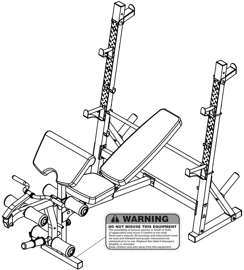
WARNING LABEL PLACEMENT
The Warning Label shown here has been placed on the Front Stabilizer. If the label is missing or illegible, please call customer service at 1-800-999-8899 for replacement. Apply the label in location shown.
FREE AND TRAINING AREA
IMPORTANT ASSEMBLY INFORMATION
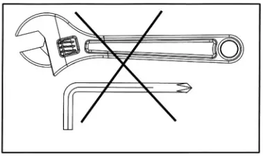
- Tools Required for Assembling the Bench: Two Adjustable Wrenches and Allen Wrenches.
- NOTE: It is strongly recommended that this equipment is assembled by two or more people to avoid possible injury.
- Ensure Carriage Bolts are inserted through the SQUARE holes on components that need to be assembled. Attach washer only to end of the Carriage Bolt.
- Use Allen Bolts or Hex Bolts inserted through the ROUND hole on components that need to be assembled.
- Always wait until all bolts are assembled onto the bench before tightening the bolts. Do not tighten each bolt right after it is installed
Fasten Nuts and Bolts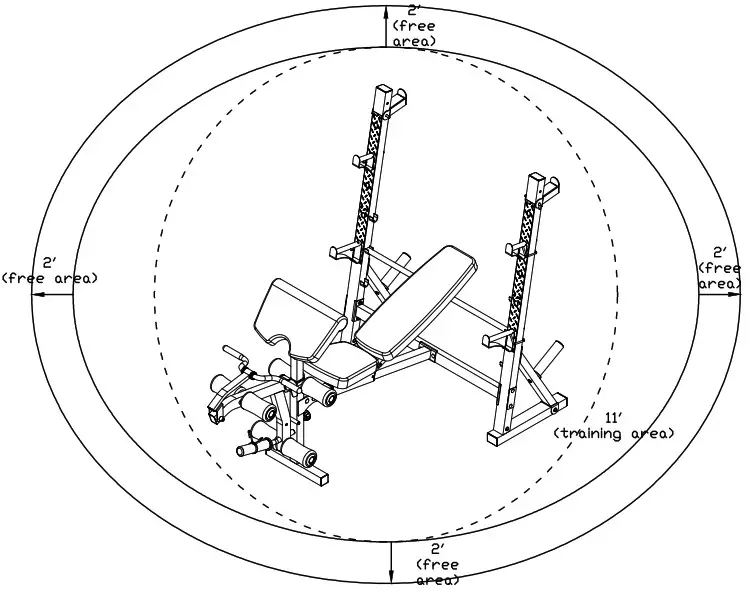 Securely tighten all Nuts and Bolts after all components have been assembled in current and previous steps.
NOTE: Do not overtighten any component with pivoting function.
Make sure all pivoting components are able to move freely.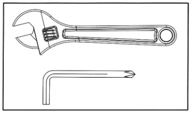
Do not tighten all Nuts and Bolts in this step.
CARE AND MAINTENANCE
- Lubricate moving parts with WD-40 or light oil periodically.
- Inspect and tighten all parts before using the equipment.
- The equipment can be cleaned using a damp cloth and mild non-abrasive detergent.
DO NOT use solvents. - Examine the equipment regularly for signs of damages or wear.
- Replace any defective components immediately and/or keep the equipment out of use until repair.
- Failure to examine regularly may affect the safety level of the equipment.
WEIGHT CAPACITY AND DIMENSION
- Maximum User weight: 300 lbs.
- Assembled Dimension: 79.53” x 48” x 60.63”
PARTS LIST
| Part # | DESCRIPTION | Q’ty | Part # | DESCRIPTION | Q’ty |
| 1 | Left Upright Beam | 1 | 37 | 1 5/8” x ¾” End Cap | 1 |
| 2 | Right Upright Beam | 1 | 38 | Ø 1” End Cap | 8 |
| 3 | Rear Stabilizer | 2 | 39 | Ø 2 3/8” Bushing | 2 |
| 4 | Main Seat Support | 1 | 40 | 2 3/8” x 2” Sleeve | 2 |
| 5 | Cross Brace | 1 | 41 | 2” x 1 ¾” Sleeve | 1 |
| 6 | Backrest Adjustment Bar | 1 | 42 | M18 Lock Knob | 2 |
| 7 | Squat Bar Catch | 2 | 43 | Rubber Bumper | 2 |
| 8 | Rear Diagonal Support | 2 | 44 | Ø 1 ½” Plastic Ring | 4 |
| 9 | Arm Curl Stand | 1 | 45 | Ø ½” Bushing | 2 |
| 10 | Leg Developer | 1 | 46 | Curl Bar Handle Grip | 2 |
| 11 | Curl Bar Handle Support | 1 | 47 | M6 x ½” Philips Screw | 1 |
| 12 | Curl Bar Handle | 1 | 48 | Ø ½” Washer | 1 |
| 13 | Leg Developer Support | 1 | 49 | U-shaped Pin | 1 |
| 14 | Front Stabilizer | 1 | 50 | Spring | 1 |
| 15 | Sliding Block | 1 | 51 | 4 ½” L-shaped Pin | 2 |
| 16 | Left Bar Catch | 1 | 52 | 3 7/8” Lock Pin | 1 |
| 17 | Right Bar Catch | 1 | 53 | 4” L-shaped Pin | 1 |
| 18 | Left Safety Catch | 1 | 54 | Spring Clip | 1 |
| 19 | Right Safety Catch | 1 | 55 | Axle | 1 |
| 20 | Seat Bracket | 1 | 56 | M10 x 3 ½” Carriage Bolt | 4 |
| 21 | Backrest Support | 2 | 57 | M10 x 2 ¾” Carriage Bolt | 2 |
| 22 | Foam Tube | 3 | 58 | M10 x 2 ½” Carriage Bolt | 1 |
| 23 | 4 ¾” x 2” Bracket | 3 | 59 | M10 x 2 3/8” Carriage Bolt | 2 |
| 24 | Weight Post | 2 | 60 | M10 x 3 ¾” Allen Bolt | 2 |
| 25 | Panel | 2 | 61 | M10 x 4 ¾” Allen Bolt | 1 |
| 26 | Backrest Board | 1 | 62 | M10 x ¾” Allen Bolt | 2 |
| 27 | Seat Pad | 1 | 63 | M10 x 5/8” Allen Bolt | 13 |
| 28 | Arm Curl Pad | 1 | 64 | M8 x 5/8” Allen Bolt | 6 |
| 29 | Rivet | 20 | 65 | M8 x 1 5/8” Allen Bolt | 4 |
| 30 | Olympic Sleeve | 3 | 66 | Ø ¾” Washer | 30 |
| 31 | Foam Roll | 6 | 67 | Ø 5/8” Washer | 10 |
| 32 | Foam Roll End Cap | 6 | 68 | M10 Aircraft Nut | 12 |
| 33 | 1 5/8” x 2 3/8” End Cap | 2 | 4# Allen Wrench | 1 | |
| 34 | 2” Square End Cap | 2 | 5# Allen Wrench | 1 | |
| 35 | 2 ¾” x 2” End Cap | 6 | 6# Allen Wrench | 2 | |
| 36 | 1” Square End Cap | 2 |
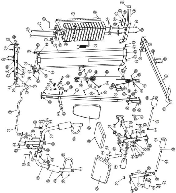
EXPLODED DIAGRAM
IMPEX® INC.
LIMITED WARRANTY
IMPEX Inc. (“IMPEX®”) warrants this product to be free from defects in workmanship and material, under normal use and service conditions, for a period of two years on the Frame from the date of purchase. This warranty extends only to the original purchaser. IMPEX’s obligation under this Warranty is limited to replacing or repairing, at IMPEX’s option.
All returns must be pre-authorized by IMPEX. Pre-authorization may be obtained by calling IMPEX Customer Service Department at 1-800-999-8899. All freight on products returned to IMPEX must be prepaid by the customer. This warranty does not extend to any product or damage to a product caused by or attributable to freight damage, abuse, misuse, improper or abnormal usage. No other warranty beyond that specifically set forth above is authorized by IMPEX.
IMPEX is not responsible or liable for indirect, special or consequential damages arising out of or in connection with the use or performance of the product or other damages with respect to any economic loss, loss of property, loss of revenues or profits, loss of enjoyments or use, costs of removal, installation or other consequential damages or whatsoever natures. Some states do not allow the exclusion or limitation of incidental or consequential damages. Accordingly, the above limitation may not apply to you.
The warranty extended hereunder is in lieu of any and all other warranties and any implied warranties of merchantability or fitness for a particular purpose is limited in its scope and duration to the terms set forth herein. Some states do not allow limitations on how long an implied warranty lasts. Accordingly, the above limitation may not apply to you.
This warranty gives you specific legal right. You may also have other rights which vary from state to state. Register on-line at www.marcypro.com
IMPEX® INC.
2801 S. Towne Ave.
Pomona, CA 91766
ORDERING REPLACEMENT PARTS
Replacement parts can be ordered by calling our Customer Service Department toll-free at 1-800999-8899
during our regular business hours: Monday through Friday, 9 am until 5 pm Pacific standard time.
[email protected]
When ordering replacement parts, always give the following information.
- Model
- Description of Parts
- Part Number
- Date of Purchase
MARCY Regenerating Magnetic Recumbent Bike ME-706

IMPORTANT SAFETY NOTICE
PRECAUTIONS
This Recumbent Bike is built for optimum safety. However, certain precautions apply whenever you operate a piece of the recumbent bike. Be sure to read the entire manual before you assemble or operate your bike.
In particular, note the following safety precautions:
Keep children and pets away from the machine at all times.
DO NOT leave children unattended in the same room with the bike.
- Only one person at a time should use the bike.
- If the user experiences dizziness, nausea, chest pain, or any other abnormal symptoms, STOP the workout at once. CONSULT A PHYSICIAN IMMEDIATELY.
- Position the machine on a clear, leveled surface. DO NOT use the bike near water or outdoors.
- Keep hands away from all moving parts.
- Always wear appropriate workout clothing when exercising. DO NOT wear robes or other clothing that could become caught in the bike. Running or aerobic shoes are also required when using the bike.
- Use the machine only for its intended use as described in this manual. DO NOT use attachments not recommended by the manufacturer.
- Do not place any sharp object around the bike.
- The disabled person should not use the bike without a qualified person or physician in attendance.
- Before using the bike to exercise, always do stretching exercises to properly warm up.
- Never operate the machine if the bike is not functioning properly.
- Read all warnings posted on the recumbent bike.
- Inspect the recumbent bike for worn or loose components prior to use. Tighten/replace any loose or wore components prior to use.
- Care should be taken in mounting or dismounting the recumbent bike. 14. This Recumbent bike is for consumer and home use only.
WARNING: BEFORE BEGINNING ANY EXERCISE PROGRAM, CONSULT YOUR PHYSICIAN. THIS IS ESPECIALLY IMPORTANT FOR INDIVIDUALS OVER THE AGE OF 35 OR PERSONS WITH PRE-EXISTING HEALTH PROBLEMS. READ ALL INSTRUCTIONS BEFORE USING ANY FITNESS EQUIPMENT. PURE-TEC LIMITED ASSUMES NO RESPONSIBILITY FOR PERSONAL INJURY OR PROPERTY DAMAGE SUSTAINED BY OR THROUGH THE USE OF THIS PRODUCT.
EXERCISE GUIDELINES
Using your REGENERATING MAGNETIC RECUMBENT BIKE will provide you with several benefits, it will improve your physical fitness, tone muscle and in conjunction with a calorie controlled diet help you lose weight.
- The Warm-Up Phase
This stage helps get the blood flowing around the body and the muscles working properly. It will also reduce the risk of cramp and muscle injury. It is advisable to do a few stretching exercises as shown below. Each stretch should be held for approximately 30 seconds, do not force or jerk your muscles into a stretch – if it hurts, STOP.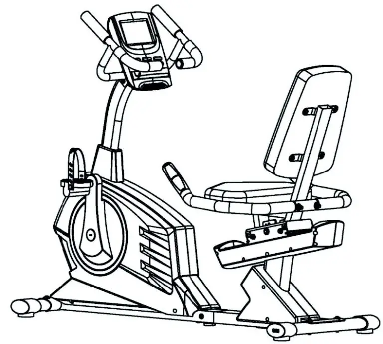
- The Exercise Phase
This is the stage where you put the effort in. After regular use, the muscles in your legs will become more flexible. Work to your but it is very important to maintain a steady tempo throughout. The rate of work should be sufficient to raise your heart beat into the target zone shown on the graph below.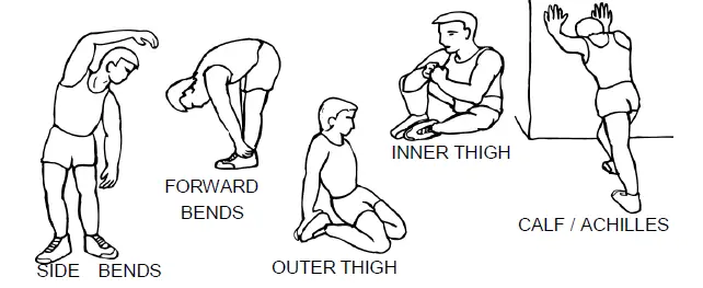
This stage should last for a minimum of 12 minutes though most people start at about 15-20 min. - The Cool Down Phase
This stage is to let your cardio-vascular system and muscles wind down. This is a repeat of the warm up exercise e.g. reduce your tempo, continue for approximately 5 minutes. The stretching exercises should now be repeated, again remembering not to force or jerk your muscles into the stretch.
As you get fitter you may need to train longer and harder. It is advisable to train at least three times a week, and if possible space your workouts evenly throughout the week.
MUSCLE TONING
To tone muscle while on your REGENERATING MAGNETIC RECUMBENT BIKE you will need to have the resistance set quite high. This will put more strain on our leg muscles and may mean you cannot train for as long as you would like. If you are also trying to improve your fitness you need to alter your training program. You should train as normal during the warm up and cool down phases, but towards the end of the exercise phase you should increase resistance making your legs work harder. You will have to reduce your speed to keep your heart rate in the target zone.
WEIGHT LOSS
The important factor here is the amount of effort you put in. The harder and longer you work the more calories you will burn. Effectively this is the same as if you were training to improve your fitness, the difference is the goal.
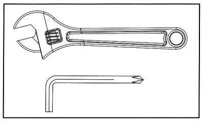
IMPORTANT ASSEMBLY INFORMATION
- Tools required for assembling the bench: 2 adjustable wrenches and Allen wrenches.
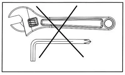
- NOTE: it is strongly recommended that this equipment is assembled by two or more people to avoid possible injury.
- Ensure carriage bolts are inserted through the SQUARE holes on components that need to be assembled. Attach washer only to end of the carriage bolt.
- Use Allen bolts or hex. bolts inserted through the ROUND hole on components that need to be assembled.
- Always wait until all bolts are assembled onto the bench before tightening the bolts.
- Do not tighten each bolt right after it is installed
Fasten nuts and bolts
Securely tighten all nuts and bolts after all components have been assembled in current and previous steps.
NOTE: do not over tighten any component with pivoting function.
Make sure all pivoting components are able to move freely.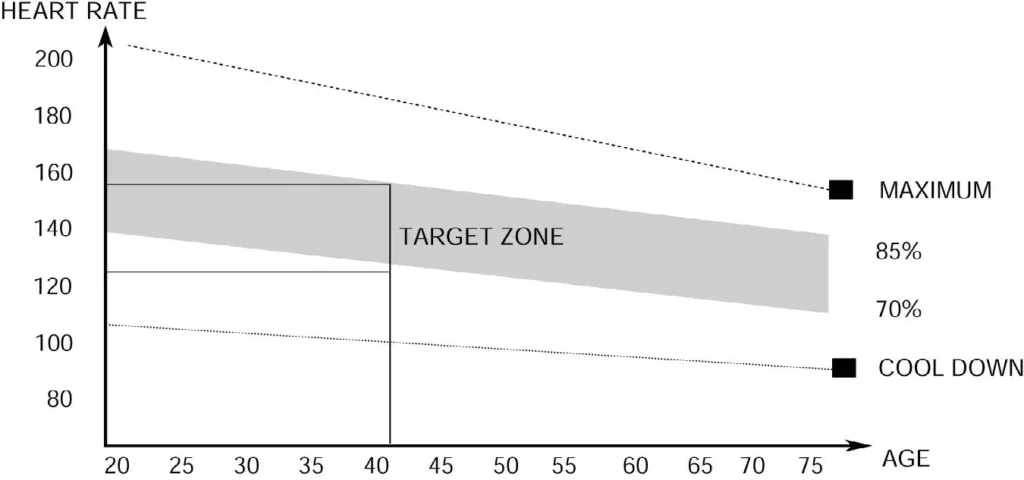
Do not tighten all nuts and bolts in this step. Do not tighten all nuts and bolts in this step.
CARE AND MAINTENANCE
- Lubricate moving parts with WD-40 or light oil periodically.
- Inspect and tighten all parts before using the equipment.
- The equipment can be cleaned using a damp cloth and mild non-abrasive detergent.
DO NOT use solvents. - Examine the equipment regularly for signs of damages or wear.
- Replace any defective components immediately and/or keep the equipment out of use until repair.
- Failure to examine regularly may affect the safety level of the equipment.
WEIGHT CAPACITY AND DIMENSION
1. Maximum user weight: 136 kg.
2. Assembled dimension in cm: 173 long x 61 wide x 107 high
PRE-ASSEMBLY CHECK LIST
| Part No. | Description | Q’ty |
| 1 | Main frame | 1 |
| 7 | Rear support tube | 1 |
| 32 | Seat support bracket | 1 |
| 4 | Front post | 1 |
| 34 | Back cushion | 1 |
| 2 | Front stabiliser | 1 |
| 3 | Rear stabiliser | 1 |
| 8 | Front post cover | 1 |
| 19L/R | Pedal (L&R) | 1 |
| 97L/R | Rear support tube Cover (L&R) | 1 |
| 5L/R | Handlebar L & R | 1 |
| 37 | Rear handlebar | 1 |
| 33 | Seat cushion | 1 |
| 23L/R | Left /Right cover for sliding tube | 1 |
| 6 | Computer | 1 |
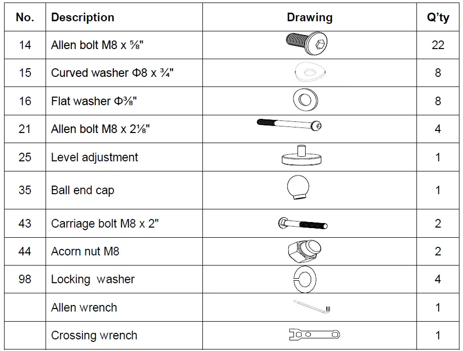
HARDWARE PARTS LIST
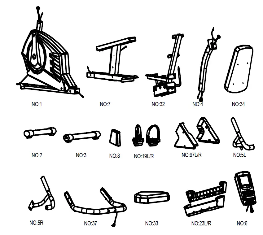
Above described parts are all the parts you need to assemble this machine.
Before you start to assemble, please check the hardware packing to make sure they are included.
CONSOLE INSTRUCTIONS
- A. Program select and setting value
1. Use the UP or DOWN keys to select program mode then press ENTER to confirm your exercise mode.
2. In the Manual mode, use the UP or DOWN keys to set up your exercise TIME, DISTANCE, CALORIES, PULSE.
3. Press the START/STOP key to start exercise.
4. When you reach the target, the computer will beep, then stop.
5. If you set up more than one target and you would like to reach next target, press START/STOP key to keep on exercising. - B. Wake-up function
The monitor will enter SLEEP mode (LCD off) after 4 minutes of inactivity. Press any button to start the monitor.
Functions and Features:
- TIME: shows your elapsed workout time in minutes and seconds. Your computer will automatically count up from 0:00 to 99:59 in one second intervals. You can also program your computer to count down from a set value by using the UP and DOWN keys. If you continue exercising once the time has reached 0:00, the computer will begin beeping, and reset itself to the original time set, letting you know your workout is completed.
- DISTANCE: displays the cumulative distance traveled during each workout up to a maximum of 99.9 MILE.
- RPM: your pedaling speed.
- WATT: the amount of mechanical power the computer is receiving from your exercise.
- SPEED: displays your workout speed value in MILES per hour.
- CALORIES: your computer will estimate the cumulative calories burned at any given time during your workout.
- PULSE: your computer displays your pulse rate in beats per minute during your workout. Pulse function works with hand-pulse. The receiver inside of meter is compatible with Polar 5kHZ chest belt
- AGE: your computer is age-programmable from 10 to 99 years. If you do not set an age, this function will always default to age 35.
- TARGET HEART RATE (TARGET PULSE): the heart rate you should maintain is called your Target Heart Rate in beats per minute.
- PULSE RECOVERY: during the START stage, leave the hands holding on grips then press “PULSE RECOVERY” key, time starts counting from 00:60 – 00:59 – – to 00:00. As soon as 00:00 is reached, the computer will show your heart rate recovery status with the grade F1.0 to F6.0.
1.0 means OUTSTANDING
1.0<F<2.0 means EXCELLENT
2.0≦F≦2.9 means GOOD
3.0≦F≦3.9 means FAIR
4.0≦F≦5.9 means BELOW AVERAGE 6.0 means POOR
Note: if no pulse signal input then the computer will show “P” on the PULSE window. If the computer shows “ERR” on message window, please press the PULSE RECOVERY key and place your hands on the pulse grip. - DISTANCE BAR: every bar indicates 100 meter or 0.1 mile.
Key function:
There are 6 buttons as follows:
- START/STOP key:
a. Quick Start function: Allows you to start the computer without selecting a program. Manual workout only. Time automatically begins to count up from zero
b. During the exercise mode, press the key to STOP exercise.
c. During the stop mode, press the key to START exercise. - UP key:
a. Press the key to increase the resistance during exercise mode.
b. During the setting mode, press the key to increase the value of Time, Distance, Calories, Age and select Gender and Program. - DOWN key:
a. Press the key to decrease the resistance during exercise mode.
b. During the setting mode, press the key to decrease the value of Time, Distance, Calories, Age and select Gender and Program. - ENTER key:
a. During the setting mode, press the key to accept the current data entry.
b. At the stop mode, by holding this key for over two seconds the user can reset all values to zero or default value.
c. During setting the Clock, press this key can accept the setting hour and setting minute. - BODY FAT key: press the key to input your HEIGHT, WEIGHT, GENDER and AGE then to measure your body fat ratio.
- PULSE RECOVERY key: press the key to activate heart rate recovery function.
Program Introduction & Operation:
Manual Program: Manual
P1 is a manual program. User can start exercise by pressing START/STOP key. The default resistance level is 5. Users may exercise in any resistance level (Adjusting by UP/DOWN keys during the workout) with a period of time or a number of calories or a certain distance.
Operations:
- Use UP/DOWN keys to select the MANUAL (P1) program.
- Press the ENTER key to enter MANUAL program.
- The TIME will flash and you can press UP or DOWN keys to set your exercise TIME.
Press ENTER key to confirm your desired TIME. - The DISTANCE will flash and you can press UP or DOWN keys to set your target DISTANCE. Press ENTER key to confirm your desired DISTANCE.
- The CALORIES will flash and you can press UP or DOWN keys to set your exercise CALORIES. Press ENTER key to confirm your desired CALORIES.
- The PULSE will flash and then you can press UP or DOWN keys to set your exercise PULSE. Press ENTER key to confirm your desired PULSE.
- Press the START/STOP key to begin exercise.
Preset Programs: Steps, Hill, Rolling, Valley, Fat Burn, Ramp, Mountain, Intervals, Random, Plateau, Fartlek, Precipice Program
PROGRAM 2 to PROGRAM 13 are the preset programs. Users can exercise with different level of loading in different intervals as the profiles show. Users may exercise in any desirous of resistance level (Adjusting by UP/DOWN keys during the workout) with a period of time or a number of calories or a certain distance.
Operations:
1. Use UP/DOWN keys to select one of the above programs from P2 to P13.
2. Press the ENTER key to enter your workout program.
3. The TIME will flash and you can press UP or DOWN keys to setting your exercise TIME. Press ENTER key to confirm your desired TIME.
4. The DISTANCE will flash and you can press UP or DOWN keys to setting your target DISTANCE. Press ENTER key to confirm your desired DISTANCE.
5. The CALORIES will flash and you can press UP or DOWN keys to setting your exercise CALORIES. Press ENTER key to confirm your desired CALORIES.
6. The PULSE will flash and then you can press UP or DOWN keys to set your exercise PULSE. Press ENTER key to confirm your desired PULSE.
7. Press the START/STOP key to begin exercise.
User Setting Program: User 1, User 2, User 3, User 4
Program 14 to 17 are the user setting programs. Users are free to create the values in the order of TIME, DISTANCE, CALORIES and the resistance level in 10 columns. The values and profiles will be stored in the memory after setup.
Users may also change the ongoing loading in each column by UP/DOWN keys, and they will not change the resistance level stored in the memory.
Operations:
1. Use UP/DOWN keys to select the USER program from P14 to P17.
2. Press the ENTER key to enter your workout program.
3. The column 1 will flash, and then use the UP/DOWN keys to create your personal exercise profile. Press ENTER to confirm your first column of exercise profile. The default level is load 1.
4. The column 2 will flash, and then use the UP/DOWN keys to create your personal exercise profile. Press ENTER to confirm your second column of exercise profile.
5. Follow the above description 5 and 6 to finish your personal exercise profiles.
Press ENTER to confirm your desired exercise profile.
6. The TIME will flash and you can press UP or DOWN keys to set your exercise TIME.
Press ENTER key to confirm your desired TIME.
7. The DISTANCE will flash and you can press UP or DOWN keys to set your target DISTANCE. Press ENTER key to confirm your desired DISTANCE.
8. The CALORIES will flash and you can press UP or DOWN keys to set your exercise CALORIES. Press ENTER key to confirm your desired CALORIES.
9. The PULSE will flash and then you can press UP or DOWN keys to set your exercise PULSE. Press ENTER key to confirm your desired PULSE.
10. Press the START/STOP key to begin exercise.
Heart Rate Control Programs: 55% H.R.C., 65% H.R.C., 75% H.R.C., 85% H.R.C., Target H.R.C.
Program 18 to Program 22 are the Heart Rate Control Programs and
Program 22 is the Target Heart Rate Control program.
Program 18 is the 55% Max H.R.C. – – Target H.R. = (220 – AGE) x 55%
Program 19 is the 65% Max H.R.C. – – Target H.R. = (220 – AGE) x 65%
Program 20 is the 75% Max H.R.C. – – Target H.R. = (220 – AGE) x 75%
Program 21 is the 85% Max H.R.C. – – Target H.R. = (220 – AGE) x 85%
Program 22 is the Target H.R.C. – – Workout by your target heart rate value.
Users can exercise according to their desired Heart Rate program by setting the AGE, TIME, DISTANCE, CALORIES or TARGET PULSE. In these programs, the computer will adjust the resistance level according to the heart rate detected. For example, the resistance level may increase every 20 seconds while the heart rate detected is lower than the TARGET H.R.C. Also the resistance level may decrease every 20 seconds while the heart rate detected is higher than the TARGET H.R.C.
Operations:
1. Use UP/DOWN keys to select one of the heart rate control program from P18 to P22.
2. Press the ENTER key to enter your workout program.
3. The AGE will flash at P18 to P21 programs and you can press UP or DOWN keys to set your AGE. The default age is 35.
4. At program 22, the TARGET PULSE will flash and you can press UP or DOWN keys to set your TARGET PULSE between 80 to 180. The default TARGET PULSE is 120.
5. The TIME will flash and you can press UP or DOWN keys to set your exercise TIME.
Press ENTER key to confirm your desired TIME.
6. The DISTANCE will flash and you can press UP or DOWN keys to set your target DISTANCE. Press ENTER key to confirm your desired DISTANCE.
7. The CALORIES will flash and you can press UP or DOWN keys to set your exercise CALORIES.
Press ENTER key to confirm your desired CALORIES.
8. Press the START/STOP key to begin exercise.
Watt Control Program: Watt Control
Program 23 is a Speed Independent Program. Press ENTER key to set up the values of TARGET WATT, TIME, DISTANCE and CALORIES. During the exercise mode, the level of resistance is not adjustable. For example, the level of resistance may increase while the speed is too slow. Also the level of resistance may decrease while the speed is too fast.
As a result, the calculated value of WATT will close to the value of TARGET WATT setup by users.
Operations:
1. Use UP or DOWN key to select the WATT CONTROL (P23) program.
2. Press ENTER key to enter your workout program.
3. The TIME will flash and you can press UP or DOWN key to set your exercise TIME. Press ENTER key to confirm your desired TIME.
4. The DISTANCE will flash and you can press UP or DOWN key to set your target DISTANCE. Press ENTER key to confirm your desired DISTANCE.
5. The WATT will flash and you can press UP or DOWN key to set your target WATT value. Press ENTER key to confirm your target WATT. The default WATT value is 100.
6. The CALORIES will flash and you can press UP or DOWN key to set your exercise CALORIES. Press ENTER key to confirm your desired CALORIES.
7. The PULSE will flash and then you can press UP or DOWN keys to set your exercise PULSE. Press ENTER key to confirm your desired PULSE.
8. Press the START/STOP key to begin exercise.
NOTE:
1. WATT = TORQUE (KGM) * RPM * 1.03
2. In this program, the WATT value will keep constant value. It means that if you peddle quickly, the resistance level will decrease and if you peddle slowly, the resistance level will increase.
Always try to keep you in the same watt value.
Body Fat Program: Body Fat
Program 24 is a special program design to calculate users’ body fat ratio and to offer a specific loading profile for users. There are 3 body types divided according to the FAT% calculated.
Type 1: BODY FAT % > 27
Type 2: 27 ≧ BODY FAT % ≧ 20
Type 3: BODY FAT % < 20
The computer will show the test results of FAT PERCENT
Operations:
- Use UP/DOWN keys to select the BODY FAT (P24) program.
- Press the ENTER key to enter your workout program.
- The HEIGHT will flash and you can press UP or DOWN keys to set your HEIGHT.
Press ENTER key to confirm your HEIGHT. The default HEIGHT is 170 cm or 5’07” (5feet 7 inches). - The WEIGHT will flash and you can press UP or DOWN keys to set your WEIGHT.
Press ENTER key to confirm your WEIGHT. The default WEIGHT is 70 kg or 155lbs. - The GENDER will flash and you can press UP or DOWN keys to select your sex. Number 1 means male and number 0 means female. Press ENTER key to confirm your Gender. The default sex is 1 (MALE).
- The AGE will flash and you can press UP or DOWN keys to set your AGE. Press ENTER key to confirm your AGE. The default AGE is 35.
- Press the START/STOP key to begin body fat measurement. If the window show E on the window, please make sure your hands are attached well on the grips or the chest belt is touching well on your body.
Then press the START/STOP key again to begin body fat measurement. - After processing your measurements, the computer will show the value of FAT % on the LCD display.
- Press START/STOP key to begin exercise.
Operation guide:
- Sleep Mode:
The computer will enter the sleep mode when there is no signal input and no keys be pressed after 4 minutes. You can press any key to wake up the computer.
Error Messages: E1 (ERROR 1):
Normal state: during workout, when the monitor did not get the count signal from the gear motor more than 4 seconds and check under successive 3 times, then the LCD will show E1.
Power on state: the gear motor will return to zero automatically, when the signal of motor cannot be detected for more than 4 seconds, then the gear motor’s driver will be cut off immediately and show the E1 on the LCD display.
All the other digital and function marks are blank, and the output signals are cut off also.
E2 (ERROR 2): when the monitor read the memory data, if the I.D. code is not correct or the memory IC damages then the monitor will show E2 immediately at power on.
E3 (ERROR 3): after 4 seconds by start mode, the computer detects the faulty motor did not leave the zero point then the LCD bar displays “E3”.
LCD Workout Graphics:

USER SETTING PROGRAM
HEART RATE PROGRAM PROFILES:

WATT CONTROL PROGRAM
EXPLODED DIAGRAM
Parts
| Part # | Description | Qty |
| 1 | Main frame | 1 |
| 2 | Front stabiliser | 1 |
| 3 | Rear stabiliser | 1 |
| 4 | Front post | 1 |
| 5 | Handlebar L & R | 1/1 |
| 6 | Computer | 1 |
| 7 | Rear support tube | 1 |
| 8 | Front post cover | 1 |
| 9 | Middle computer wire | 1 |
| 10 | Front extension hand pulse wire | 1 |
| 11 | Upper foam grip for stationary handlebar | 2 |
| 12 | Screw M5 x ½” | 6 |
| 13 | End cap for handlebar | 4 |
| 14 | Allen bolt M8 x ⅝” | 22 |
| 15 | Curved washer Φ8 x ¾” | 8 |
| 16 | Flat washer Φ⅜” | 17 |
| 17 | Middle extension hand pulse wire | 1 |
| 18 | Lower computer wire | 1 |
| 19 | Pedal (L&R) | 1/1 |
| 20 | End cap for front stabiliser L&R | 1/1 |
| 21 | Allen bolt M8 x 2⅛” | 4 |
| 22 | Rear extension hand pulse wire | 1 |
| 23 | Left /Right cover for sliding tube | 1/1 |
| 24 | End cap for rear stabiliser | 1/1 |
| 25 | Level adjustment | 1 |
| 26 | Self taping screw ST5 x ½” | 24 |
| 27 | Bumper | 2 |
| 28 | Screw M5 x ⅜” | 6 |
| 29 | Quick release handle | 1 |
| 30 | Lower foam grip for handlebar | 2 |
| 31 | End cap for seat support bracket | 2 |
| 32 | Seat support bracket | 1 |
| 33 | Seat cushion | 1 |
| 34 | Back cushion | 1 |
| 35 | Ball end cap | 1 |
| 36 | End cap for rear handlebar | 2 |
| 37 | Rear handlebar | 1 |
| 38 | Upper hand pulse sensor | 2 |
| 39 | Lower hand pulse sensor | 2 |
| 40 | Screw M2.5 | 4 |
| 41 | Foam grip for rear handlebar | 2 |
| 42 | Hand pulse wire | 1 |
| 43 | Carriage bolt M8 x 2″ | 2 |
| 44 | Acorn nut M8 | 2 |
| 45 | Grommet | 1 |
| 46 | End cap for pedal cover | 2 |
| 47 | Flange screw | 2 |
| 48 | Pedal cover | 2 |
| 49 | Left support tube for pedal cover (L&R) | 1/1 |
| 50 | Back cover for pedal cover | 2 |
| 51 | Self tapping screw ST5 x ⅜” | 10 |
| 52 | Phillip screw M5 x ⅜” | 4 |
| 53 | Fixed plate | 2 |
| 54 | Allen bolt M6 x ¾” | 4 |
| 55 | Self tapping screw ST5 x ¾” | 6 |
| 56 | Left / Right chain cover | 1/1 |
| 57 | Flange nut | 2 |
| 58 | C-clip Φ½” | 4 |
| 59 | Axle for flywheel | 1 |
| 60 | Flywheel | 1 |
| 61 | Magnet assembly | 1 |
| 62 | Aircraft nut M8 | 6 |
| 63 | Allen bolt M8 x 2⅛” | 1 |
| 64 | C-clip Φ⅝” | 2 |
| 65 | Bearing 6203 | 2 |
| 66 | Hex bolt M6 x 1″ | 1 |
| 67 | Hex nut M6 | 2 |
| 68 | Spring for magnet assembly | 1 |
| 69 | Spring for idler wheel | 1 |
| 70 | Eye bolt | 1 |
| 71 | Nut M8 | 1 |
| 72 | Idler wheel | 1 |
| 73 | Powder spacer | 1 |
| 74 | Pulley | 1 |
| 75 | Aircraft nut M6 | 4 |
| 76 | Axle for pulley | 1 |
| 77 | Allen bolt M6 x ⅝” | 4 |
| 78 | Sensor bracket | 1 |
| 79 | Belt | 1 |
| 80 | Bushing for seat post | 1 |
| 81 | Bolt M8 x ¾” | 1 |
| 82 | Motor | 1 |
| 83 | Power wire | 1 |
| 84 | Sensor wire | 1 |
| 85 | Motor cable | 1 |
| 86 | Screw for generator | 4 |
| 87 | Generator | 1 |
| 88 | End cap for sliding tube | 2 |
| 89 | Support bracket for sliding tube | 1 |
| 90 | Sliding wheel | 4 |
| 91 | Bearing | 8 |
| 92 | Allen bolt M8 x 1½” | 4 |
| 93 | Sleeve for wheel | 8 |
| 94 | Seat bracket | 1 |
| 95 | Bushing | 2 |
| 96 | Phillip screw M6 x ⅜” | 4 |
| 97 | Rear support tube cover (L&R) | 1/1 |
| 98 | Locking washer | 4 |
| 99 | Audio wire | 1 |
LIMITED WARRANTY
Pure-Tec warrants this product to be free from defects in workmanship and material, under normal use and service conditions. Please refer to www.puretecfitness.com for warranty terms. This warranty extends only to the original purchaser and is valid for home use only. Pure-Tec’s obligation under this Warranty is limited to replacing damaged or faulty parts at Pure-Tec’s option.
All returns must be pre-authorised by Pure-Tec. This warranty does not extend to any product or damage to a product caused by or attributable to freight damage, abuse, misuse, improper or abnormal usage, purchasers own repairs or for products used for commercial or rental purposes. No other warranty beyond that specifically set forth above is authorised by Pure-Tec .
Pure-Tec is not responsible or liable for indirect, special or consequential damages arising out of or in connection with the use or performance of the product or other damages with respect to any economic loss, loss of property, loss of revenues or profits, loss of enjoyments or use, costs of removal, installation or other consequential damages or whatsoever natures.
The warranty extended hereunder is in lieu of any and all other warranties and any implied warranties of merchantability or fitness for a particular purpose is limited in its scope and duration to the terms set forth herein.
Your statutory rights are not affected.
ORDERING REPLACEMENT PARTS
Replacement parts can be ordered by contacting our Customer Solutions Department, Monday to Friday, 8am – 5pm GMT :
Pure-Tec Limited www.puretecfitne
Tel: +44
Email: [email protected]
Monday – Friday 0800 – 1700GMT
When ordering replacement parts, please give the following information,
1. Model
2. Description of parts
3. Part number
4. Date of purchase