LINKSYS User Guide
RE6300/RE6400
Introduction
This User Guide can help you connect the extender to your network and solve common setup issues. You can find more help from our award-winning, 24/7 customer support at
Linksys.com/support.
Contents
Overview . . . . . . ………………………..1
How to install the range extender……………. 2
How to access the browser-based utility ……… 5
Using Wi-Fi Protected Setup………………… 7
How to use Site Survey…………………….. 9
Cross-Band
AC Power Pass-Through
Wireless Music Playback
Troubleshooting…………………………. 10
Specifications………………………….. 13
Overview
Front
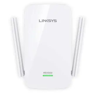
RE6300
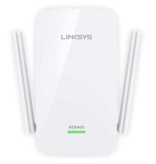
RE6400
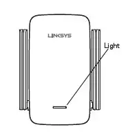
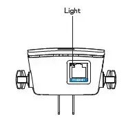
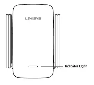
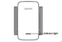
The light on the front of the range extender gives you information about power, updating and signal strength.
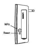
Side
Power Switch European versions only.
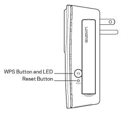
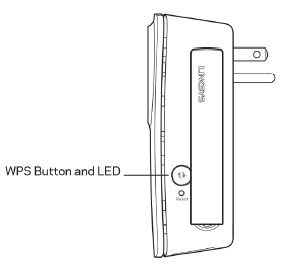
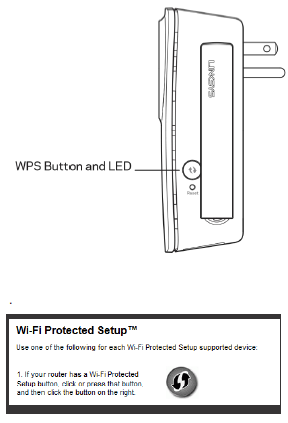
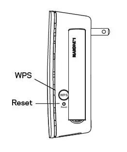
Wi-Fi Protected Setup Button and LED Use Wi-Fi Protected Setup to automatically and securely add compatible wireless devices to your network. Refer to Using Wi-Fi Protected Setup on page 7.
Reset Press and hold for about five seconds to reset to factory defaults. You can also restore the defaults from the Administration> Factory Defaults Screen in the extender’s browser-based utility.
Bottom
How to install the range extender
Before setup, unplug or disconnect any range extenders on the network.
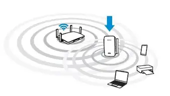
1. Plug in the range extender midway between your router and the area without Wi-Fi.
Be sure you have at least 50% of your router’s Wi-Fi signal at that point on the device you will use for setup. The setup software will help you find the best spot if you have trouble.
2. Wait for a solid light on the cover of the range extender. It could|take up to two minutes. On a computer, phone or tablet, connect to the Wi-Fi network “Linksys Extender Setup.”
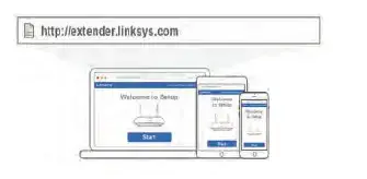
3. If setup doesn’t start automatically, open a browser to http://extender.linksys.com.
Linksys’s Spot finder technology will help you find the right location for your range
extender if you have trouble. You will be guided to place the ra nge extender closer or farther from your router to improve the signal. if you nailed it with your first placement you will not see Spot finder screens.
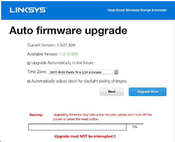
4. During setup you will be asked whether you want the range extender to update itself
automatically. If you allow automatic updates, the range extender will download and install updates when released by Unksys. Automatic updates will take place overnight so they do not disrupt your network activit y.
You also can decide to manually update your range extender at your convenience.
Post set-up LED behavior menbon here as well and in the QSG
TIP
You can also connect the range extender by using Wi.-Fi Protected Setup. For more
information, see “Using Wi-Fi Protected Setup” on page 7.
Special Feature – Music Streaming
Wireless Music Playback
Stream music through your AC12OO MAX range extender to connected speakers.
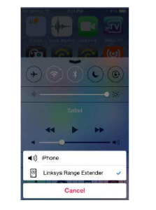
iOS devices:
. Connect iOS device to the same Wi.-Fi network as your range extender.
. Swipe up from the bottom of your screen.
. Tap on Linksys Range Extender.
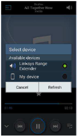
Android devices
For Samsung Galaxy
– Connect Galaxy device to the same Wi-Fi network as your range extender.
– Select Music app 
– Choose music file and tap Screen Mirroring icon
– Choose Linksys Range Extender.
Your screen might look different depending on your device model and version of Android.
For other Android devices, stream music with MediaHouse, UPnPlay, Skifita, ArkMC,
BubbleUPnP, Pixel Media, and 2Player 2.0.
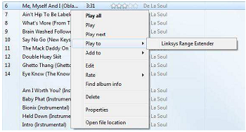
Windows
– Open Windows Media Player
– Right-click on music file and choose Linksys Range Extender.
This list of supported media players is subject to change with the release of new
software or mobile apps.
– Windows users can stream music with Windows Media Player12.
– Mac users can stream music with proprietary software or the SofaPlay app..
– Android users can stream music with MediaHouse, UPnPlay, Skifita, ArkMC,
BubbleUPnP, Pixel Media, and 2Player 2.0.
– IOS devices including iPhone, iPad or iPod can stream music with proprietary
software or other apps such as, , ArkMC, Smartstor Fusion, , Mconnect, and DK
UPnP/DLNA.
– The extender supports MP3, FLAC, WAV, WMA and AAC file formats, as long as
those formats are supported by the device and app doing the streaming.
– The 3.5mm stereo port supports earphones and powered speakers.
How to access the browser-based utility
After setting up the extender use the extender-based utility to change any
settings.
On a computer or device that is connected to your range extender, open any browser
(Internet Explorer, Chrome, Firefox, Safari, etc.), and enter extender.linksys.com in the address bar.
You will be prompted to enter a user name and password. If yo u did not change them
during setup, leave the user name blank and enter admin” in the password field. If
you customized the $510 and passwo rd, enter those credentials.
If you are connected to your local network, but not to the range extender, you will need to enter the range extender’s IP address in your browser to access the extender’s
settings.
TIP
If you are unable to access the range extender’s seUings, do one of the foSowing:
Find the r ange extender’s IP address by going to your routef~s administration page and looking for the range extender under connected devices.
Windows XP:
1. Enable UPnP:
a) Click Start, Control Panel, Add a Remove Program, then dick Add/Remove Windows Components.
b) Select Network Servfces, then cSck Oefails.
c) Select UPnP User Interface, then click OK
2. Open Windows Expbrer. Click My Network Places on the lea panel.
3. L7k for the RE677icorf on the right panel. (You might be required to change the firewall settings to albw the display of networked computers. Refer to your operating system’s help for instructions)
Windows 8, Windows 7, or VisW:
1. Open Windows Explorer (File Expbrer in Windows 8). Click Networlk Look for the RE677 icon on the right panel. (You might be required to change the frewaS settings to aSow the display of networked computers. Refer to your operating system’s help for instructions .)
2. Right-click the RE6700 icon. Click Properfies. Click on the address fink in Device webpage.
Mac OS X:
1. Open Sahri. Be sure that Bonjour is included in the Bookmarks menu and Favorites bar.
a. Go to Safari Preferences > Advanced and be sure each Bonjour box is selected.
2. Find Bonjour in the Bookmarks menu or Favorites bar and choose Linksys Range
Extender. ” If you have changed your network name and password, choose the network
name and enter the password you created.
Using range extender seNings
Click Help cn the right side cf the screen fcr additicnal infcrmation cn the screen~s
options. Ch anges tc settings will net be effective untS you cBck Save at the boffom cf the screen. You also can click Cancel tc dear any changes.
Using Wi-Fl Protected Setup
WiFi Protected Setup~ makes it easy to connect your extender to your network, and
conned other de~es to your network through the extepder.
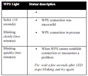
Wi-Fi Protected ktup light activity
Connecting the extender to an existing access point
If your access point or router supports it, you can use Wi-Fi Protected Setup to connect the range extender to the access point or router. Log in to the browser-based utility and click on WPS in the left navigation bar. Choose from the setup methods below to connect the extender.
NOTE
If you have an access point or a router that does not support Wi-Fi Protected Setup,
note the wireless settings, and then manually configure the extender. Connecting with the Wi-Fi Protected Setup Button Use this method if your router or access point has a Wi-Fi Protected Setup button
1. Press the Wi-Ff Protected Setup button on the extender. If you have a dual-band
router you will do this again to extend the second network . The 2.4 GHz band will
be extended first
2. Click the Wi-R Protected Setup button on the routef`s WiFi Protected Setup
screen (if avaSable), OR press and hold the Wi-Fi Protected Setup bu&on on the
router for one second. When the connection is complete, the Wi-Fi Protected Setup
fight on the extender Wat be solid.
3. If you used the extender’s WI-Fi Protected Setup screen, ~ OK in that screen
within two minutes.
TIP
You can also access W PS in the browser-based utility by clicking WPS in the left
navigation bar.
Connecting with the range extender’s PIN
The Wi Fi Protected Setup PIN (Personal Identification Number) can be found on the
produd label on the back of the extender. You can use this method only if your route~s
administration utiBty has a Wi-Fi Protected Setup menu.
1. Enter the extender~s PIN into the appropriate field on the router~s Wi- Fi Protected Setup screen. Click Register. When the connection is complete, the Wi-Fi Protected Setup light on the extender win be send.
2. Click OK Connecting devices to your network through the extender Choose from the methods below to connect devices that support Wi-Fi Protected Setup
to your network. Delete the screen below
NOTE
Repeat the instructions for each chem device that supports Wi Fi Protected Setup.
Connecting with the Wi-Ff Protected Setup Button
Use this method if your chem device has a WiFi Protected Setup button.
1. Press the Wi Fl ?retooled Setup button on the Ghent device.
2. CliGk the WI-R Protooted Setup button on the extenders WiFl ProteGted Setup
sGfeefi, OR press and hold the Wi-Fi ?retooled Setup bu&on on the side of the
extender for one second When the GOfffleGtfOfl is complete, the Wi-Fi ?retooled
Setup fight on the extender win be scud.
3. If using the extenders WiFl ProteGted Setup sGreefl, be sure to dfGk OKwithifl two
minutes or you will have to start over.
Connecting with the client devices PIN
Use this method if your diefff device has a Wi-Fi ProteGted Setup PIN (Personal
Identification Numbef).
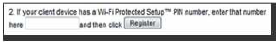
1. Enter the PIN from the client device in the field on the extenders WiFl ProteGted
Setup sGreefl.
2. CliGk Register on the extenders WI-Fi ProteGted Setup sGreefl. When the GonrfeGflon is complete, the Wi-Fi Protected Setup light on the extender will be solid.
3. CliGk OK on the extender~s Wi-Fi ?retooled Setup sGfeefi within two minutes or you
will have to start over.
Connecting with the extendeYs PIN
Use this method if your client device asks for the extenders PIN
1. On the client device , enter the PIN listed on the extender~s Wi-Fi ?retooled Setup
sGfeefi. (It is also Bsted on the product label on the back d the exteflder.) When the
GonrfeGflon is complete, the Wi-Fi Protected Setup light on the extender will be solid.
2. CliGk OK on the extender~s Wi-Fi ?retooled Setup sGfeefi within two minutes.
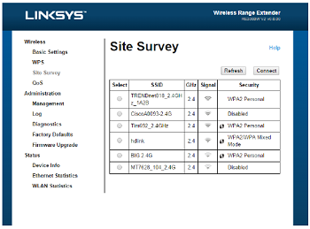
How to use Site Survey
Site Survey gives a snapshot of aH neighboring access points and wireless routers
within range of the extender.
To open the Site Survey page:
1. log in to the browser-based utility (see How to access the browser- based utility”
on page 5).
2. Click the Wireless tab. CHck the Site Survey page.
3. Select-To oonnecf to a wireless network, click the bu&on next to the wireless
netwof k name (SSID) in the Select column, and click Connect.
4. SSID-Displays the name of neighboring wireless networks.
5. GHz-Displays the radio band (in GHz) of the neighboring wireless networks
6. Signal Stf engM -Displays the relative position of the neighboring access points
by indicating the power of the wireless signal received: dot only = 25% dot + one
wave = 50%, dot + two waves = 75%, dot + three waves = 1O0%. If no waves are
displayed, your extender is too far from the upstream access point or the signal is
blocked Try to keep the signal strength between 60% and 17% for optimum
performance
7. Security-Displays the mode of security in use by the neighboring APs. If a network
supports Wi-R Protected Setup, the Wi-Fi Protected Setup icon is also displayed.
To connect your extender wah an access point or router in Sac Survey, you will
need to know the password or passphrase d Me network on Mat device.
1. Selecf the network name (SSID) that you want to repeat with your extender by
clicking the corresponding button in the Selecf column.
2. Click Connect, When prompted, enter the password a passphrase used to secure
your wireless network. The type d security information required in this screen must
match your access point or router’s wireless security seuings.
TIP: For dual-band networks, be sure to connect to both bands, 2.4 GHz and 5 GHz.
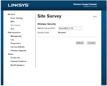
3. Click Save. Your extender wireless parameters should be configured. The wireless
interface will restart, and the extender will connect to the access point or router you have chosen.
Cross-Band
Cross-Band is the simultaneous use of both bands for high-speed data transfer and
uninterrupted streaming and gaming.
Troubleshooting
NOTE Your RE6700 works on 2.4GHz and 5 GHz networks.
You cannot get your extender connected
Check the position of your router and extender
– For first-time setup, you may need to place the extender closer to the router .
After you.ve set up your extender, you can unplug it and move it to the final
location .
– To reduce signal obstfudions, tr y alternate locations for the router and extender.
– Avoid placing the router and extender near metal objects, masonry waifs, and reflective surfaces such as glass or mirmrs
– Avoid placing the router and extender near other electronics that may
cause signal interference
If you’re using Wi-Fi Profeded Setup to conned, wait until the Wf Fi Protected
Setup indicator stops blinking before tr ying to make the connection again.
You cannot access your range extender.
To access your range extender , you must be connected to your own netwoff<. ff
you currently have wireless Internet access, the problem may be that you have
accidentally conneded to a different wireless network.
For Mac instructions, see “To fix the problem on Mac computers:” on page 12
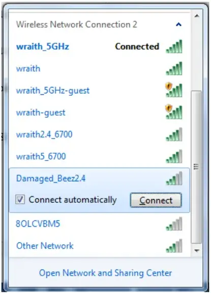
To fix the problem on Windows computers:

1. On your Windows desktop, right-click the wireless icon in the system tray. The icon might look different depending on which vef sion of Windows you af e running.
2. Click View Available Wireless Networks.
3. Select your network name. Click Connect. In the example below, the computer was connected to another wireless network named JimsRouter. The name of the correct network, BronzeEagle in this example, is selected.
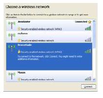
4. If you are prompted to enter a network key, type your password (Security
Key) into the Network key and Confirm network key fields. Click Conned
You should now be able to access the range extender’s browser-based
utility.
To fix the problem on Mac computers:
1. In the menu bar across the top of the screen, click the Wi-Fi icon.
Unksys Conned has automatically assigned your network a name.
In the example below, the computer was connected to another wireless
networ k named JimsRouter . The name of the Linksys E-Series network,
BronzeEagle in this example, is selected.
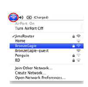
2. Select the wireless network name of the router you want to connect to.
3. Type your wireless network password (Security Key) into the Password
field. Click OK.
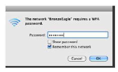
You should now be able to access the range extender’s browser’based utility.
You have intermittent connec6on problems
Plug in the range extender midway between your router and the area without Wi-Fi. Be
sure you have at least 50% of your router~s WI-Fi signal at that point on the device you used for setup.
Visit linksys.com/support for award-winning 24/7 technical support BELKIN, LINKSYS and many product names and logos are trademarks of the Belkin group of companies. Third-party trademarks mentioned are the property of their respective owners. Licenses and notices for third party software used in this product may be viewed here: http://support.linksys.com/en-us/license. Please contact
http://support.linksys.com/en-us/gplcodecenter for questions or GPL source code requests.
© 2015 Belkin International, Inc. and/or its affiliates. All rights reserved.
Federal Communication Commission Interference Statement
This device complies with Part 15 of the FCC Rules. Operation is subject to the following two conditions:
(1)This device may not cause harmful interference, and
(2) this device must accept any interference received,including interference that may cause undesired operation. This equipment has been tested and found to comply with the limits for a Class B digital device, pursuant to Part 15 of the FCC Rules. These limits are designed to provide reasonable protection against harmful interference in a residential installation. This equipment generates, uses and can radiate radio frequency energy and, if not installed and used in accordance with the instructions, may cause harmful interference to radio communications. However, there is no guarantee that interference will not occur in a particular installation. If this equipment does cause harmful interference to radio or television reception, which can be determined by turning the equipment off and on, the user is encouraged to try to correct the interference by one of the following measures:
– Reorient or relocate the receiving antenna.
– Increase the separation between the equipment and receiver.
– Connect the equipment into an outlet on a circuit different from that
to which the receiver is connected.
– Consult the dealer or an experienced radio/TV technician for help.
FCC Caution: Any changes or modifications not expressly approved by the party responsible for compliance could void the user’s authority to operate this equipment. This transmitter must not be co-located or operating in conjunction with any other antenna or transmitter.
Operations in the 5.15-5.25GHz band are restricted to indoor usage only.
Radiation Exposure Statement:
This equipment complies with FCC radiation exposure limits set forth for an uncontrolled environment. This equipment should be installed and operated with minimum distance 22cm between the radiator &
your body.
Note: The country code selection is for non-US model only and is not available to all US model. Per FCC regulation, all WiFi product marketed in US must fixed to US operation channels only.
Industry Canada statement:
This device complies with RSS-210 of the Industry Canada Rules. Operation is subject to the following two conditions: (1) This device may not cause harmful interference, and (2) this device must accept any interference received, including interference that may cause undesired operation. Ce dispositif est conforme à la norme CNR-210 d’Industrie Canada applicable aux appareils radio exempts de licence. Son fonctionnement est sujet aux deux conditions suivantes: (1) le dispositif ne doit pas produire de brouillage préjudiciable, et (2) ce dispositif doit accepter tout brouillage reçu, y compris un brouillage susceptible
de provoquer un fonctionnement indésirable.
Caution :
(i) the device for operation in the band 5150-5250 MHz is only for indoor use to reduce the potential for harmful interference to co-channel mobile satellite systems;
(ii) high-power radars are allocated as primary users (i.e. priority users) of the bands 5250-5350 MHz and 5650- 5850 MHz and that these radars could cause interference and/or damage to LE-LAN devices.
Avertissement:
(i) les dispositifs fonctionnant dans la bande 5 150-5 250 MHz sont réservés uniquement pour une utilisation à
MHz et que ces radars pourraient causer du brouillage et/ou des dommages aux dispositifs LAN-EL.
Radiation Exposure Statement:
This equipment complies with IC radiation exposure limits set forth for an uncontrolled environment. This equipment should be installed and operated with minimum distance 27cm between the radiator & your body.
Déclaration d’exposition aux radiations:
Cet équipement est conforme aux limites d’exposition aux rayonnements IC établies pour un environnement non contrôlé. Cet équipement doit être installé et utilisé avec un minimum de 27 cm de distance entre la source de
rayonnement et votre corps.
![]()
USER GUIDE
AC1200 DUAL-BAND WiFi 5 ROUTER
Model E5600
Product Overview
Front
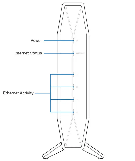 Power light–Blinks blue while router is starting up and during WPS pairing. Blinks yellow if WPS pairing fails
Internet status light–Is solid blue when connected to the internet and solid yellow when not connected.
Ethernet activity lights–Each light will be solid blue if an ethernet cable is connected to the corresponding port. They will blink blue if there is activity on the port.
Back
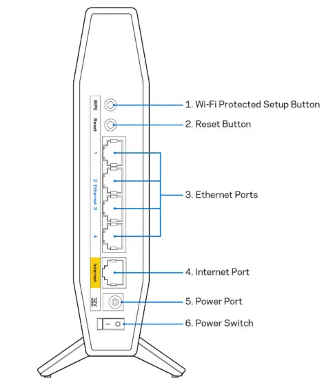 Wi-Fi Protected SetupTM (WPS) button (1)–Press to easily configure wireless security on Wi-Fi Protected Setup-enabled network devices. The light under the button will blink while WPS pairing is active.
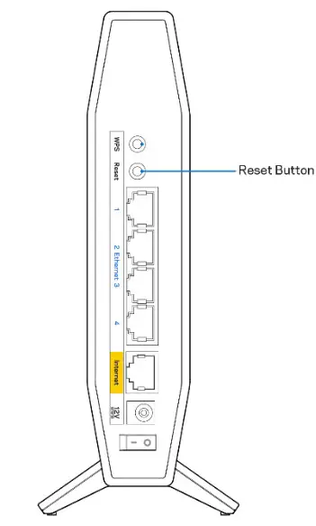
Reset button (2)–Press and hold for until the power LED starts flashing to reset the router to factory settings.
Ethernet ports (3)–Connect Ethernet cables (also called network or internet cables) to these Fast Ethernet (10/100/1000) ports and to other wired devices on your network. The lights under the ports will light up only when an Ethernet cable is plugged in and there is data traffic on the cable.
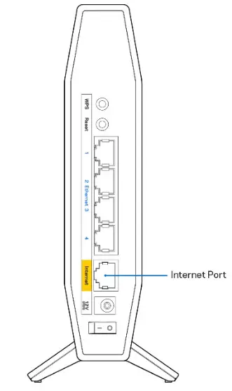
Internet port (4)–Connect an Ethernet cable to this port and to your modem. The light under the port will light up only when an Ethernet cable is plugged in and there is data traffic on the cable.
Power port (5)–Connect the included AC power adapter to this port.
Power switch (6) –Press | (ON) to turn on the router.
Setting Up: Basics
Where to find more help
In addition to this user guide, you can find help at Linksys.com/support/E5600 (documentation, downloads, FAQs, technical support, live chat, forums)
Note–Licenses and notices for third-party software used in this product may be viewed on http://support.linksys.com/en-us/license. Please contact http://support.linksys.com/enus/gplcodecenter for questions or GPL source code requests.
How to install your router
- If replacing an existing router, disconnect that router first.
- Plug in the router to a power source. Make sure the power switch is in the | (ON) position.
- Connect your new router to your modem or modem router.
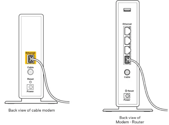
A Modem OR B Modem-Router Plug one end of the included ethernet cable into the yellow Internet port on your new router. If you have a modem, plug the other end into the Ethernet (LAN) port on the modem. Plug one end of the included ethernet cable to the yellow Internet port on your new router. If you have a modem-router, plug the other end into any available port. - Connect to the network name shown in the Quick Start Guide that came with your router. (You can change the network name and password later.) Select the option to automatically connect to this network in the future. If you need help connecting to the network refer to your device documentation on the provided CD.
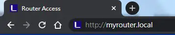
Note–You will not have internet access until router setup is complete. - Enter http://myrouter.local in a web browser. Follow the on-screen instructions to complete setup. You also can enter 192.168.1.1 in a browser to start setup.

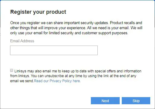
- Once you are finished with setup, please be sure to register your router so we can keep you informed security updates, product recalls, and other things that will improve your experience.
Advanced Configuration
How to open the browser-based utility
To access some advanced settings, you need to open the browser-based utility. Make sure you are connected to the router, open a web browser and enter http://myrouter.local in a web browser or go to 192.168.1.1.
 The router will prompt you for a password.
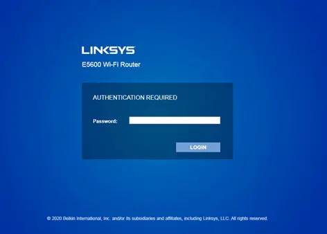 If you changed the password during setup, enter the new password. Click LOGIN. If you didn’t change the password, or skipped setup altogether, the default password is “admin”.
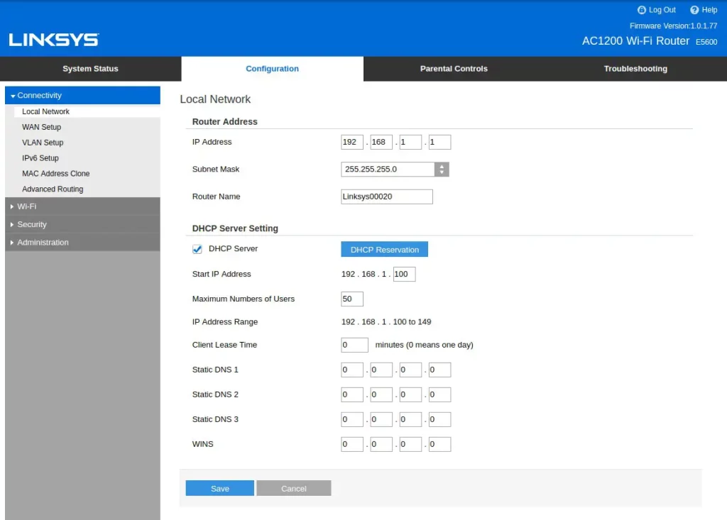
Basic Router Settings
This screen allows you to change the router’s basic configuration.
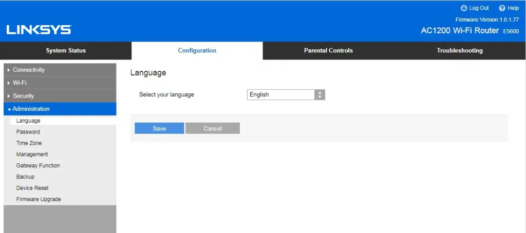
Language
Select your language–To change language, select one from the drop-down menu. The language of the browser-based utility will change within five seconds.
Internet Setup
The Internet Setup section configures the router to your internet connection. This information can be provided by your Internet Service Provider (ISP).
Internet Connection Type–Select the type of internet connection your ISP provides from the dropdown menu.

- Automatic Configuration DHCP (default)
Keep the default only if your ISP supports DHCP or if you connect using a dynamic IP address. (This option usually applies to cable connections.) - Static IP
Select if you are required to use a fixed IP address to connect to the internet. - PPPoE
Select if you have a DSL connection and your ISP uses Point-to-Point Protocol over Ethernet (PPPoE). - PPTP
Point-to-Point Tunneling Protocol (PPTP) is a service that generally applies to connections in Europe. If your PPTP connection supports DHCP or a dynamic IP address, select Obtain an IP Address Automatically. If you are required to use a fixed IP address to connect to the internet, select Specify an IP Address and configure the options that appear. - L2TP
Layer 2 Tunneling Protocol (L2TP) is a service that generally applies to connections in Israel.
Note–Connect on Demand or Keep Alive are options when choosing PPPoE, PPTP, and L2TP. They let you choose whether the router connects to the internet only as needed (useful if your ISP charges for connect time), or if the router should always be connected. Select the appropriate option. - Bridge Mode
Bridge Mode disables all router capabilities and turns the router into an access point. The router will cease to act as a DHCP server and its built-in firewall, as well as the NAT features, will no longer be in effect. - Wireless Bridge
A wireless bridge wirelessly connects to your main router and can share the internet connection with devices connected to the bridge’s Ethernet ports.
Basic Wireless Settings
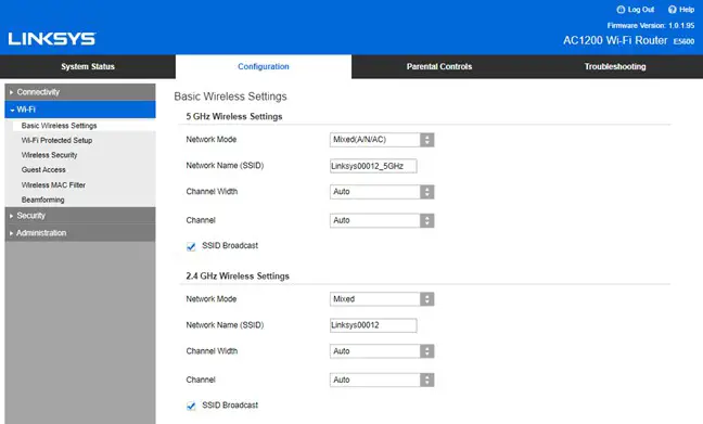
Network Mode–Select the wireless standards your network will support.
- Mixed (default) Keep the default if you have Wireless-N, Wireless-N, and Wireless-AC devices in your network.
- Wireless-A Only Select if you have only Wireless-A devices.
- Wireless-N Only
Select if you have only Wireless-N devices. - Disabled
Select if you have no Wireless-A, Wireless-N, and Wireless-AC devices in your network. Note–You may select Mixed, Wireless-N/AC Only or Disabled for the 5 GHz band. If you are not sure which mode to select, keep the default, Mixed.
Network Name (SSID)
The Service Set Identifier (SSID) is a name used by devices to connect to a wireless network. SSIDs are case-sensitive and must not exceed 32 characters. The default SSIDs for the 2.4 GHz and 5 GHz networks are LinksysXXXXX and LinksysXXXXX_5GHz, respectively. The Xs represent the last five digits of the router’s serial number, which can be found on the bottom of the router. If you changed the SSID, both bands have the new SSIDs. You may give them different names through the browser-based utility.
Note–If you restore the router’s factory default settings (by pressing the Reset button or using the Administration > Factory Defaults screen), the Network Name will return to its default value. Change the Network Name back to its original name, or you will have to reconnect all devices on your wireless network to the new network name.
Channel Width
Keep the default, Auto (20 MHz or 40 MHz), for best performance in a 2.4 GHz network using Wireless-B, Wireless-G and Wireless-N devices. For a channel width of 20 MHz, select 20 MHz only. For the best performance in a 5 GHz network, keep the default 20, 40 or 80 MHz.
Channel
Select the channel from the drop-down list. Keep the default, Auto, if you are not sure which channel to select.
SSID Broadcast
Keep the default, Enabled, to broadcast the router’s SSID. When wireless clients survey the local area for wireless networks to associate with they will detect the SSID broadcast by the router. Attempting to hide your Wi-Fi name does not make your Wi-Fi more secure. Anyone truly interested in accessing your network can find it even if you turn off this feature. If you still do not want to broadcast the router’s SSID, select Disabled.
Wireless Security
The router offers the following wireless security options: WPA2 Personal (WPA stands for Wi-Fi Protected Access.)
| Security Option | Strength |
| WPA2 Personal | Strongest |
Security Option Settings
WPA2 Personal
If you select WPA2 Personal, each device in your wireless network MUST use WPA2 Personal and the same passphrase.
 Passphrase–Enter a passphrase of 8-63 characters. This is the Wi-Fi password that provides access to the network. It can be the same as entered in setup.
Disabled
If you choose to disable wireless security, you will be informed that wireless security is disabled when you first attempt to access the internet. You will be given the option to enable wireless security or confirm that you understand the risks but still wish to proceed without wireless security.

Troubleshooting
You can find more help from our award-winning customer support at Linksys.com/support/E5600.
Your router was not successfully set up
If you could not complete setup in the browser-based interface, you can try the following:
- Press and hold the Reset button on your router with a paperclip or pin until the power light on the front of the router turns off and starts blinking (about 10 seconds). Type 192.168.1.1 in a browser to try setup again.
- Temporarily disable your computer’s firewall (see the security software’s instructions for help). Install the router again.
- If you have another computer, use that computer to install the router.
Your Internet cable is not plugged in message
If you get a “Your Internet cable is not plugged in” message when trying to set up your router:
- Make sure that an ethernet or internet cable (or a cable like the one supplied with your router) is securely connected to the yellow Internet port on the back of the router and to the appropriate port on your modem. This port on the modem is usually labeled Ethernet.
- Make sure that your modem is connected to power and is turned on.
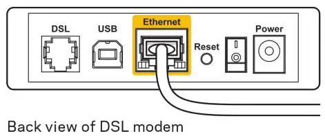
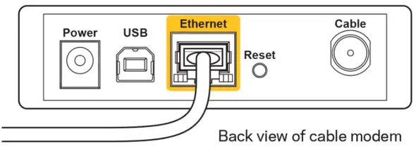
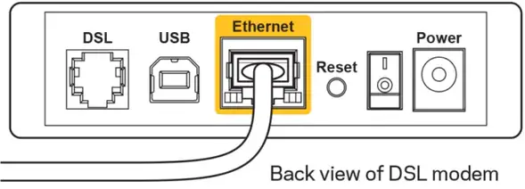
If your internet service is cable, verify that the cable modem’s CABLE port is connected to the coaxial cable provided by your ISP. If your internet service is DSL, make sure that the DSL phone line is connected to the modem’s DSL port. - If your computer was previously connected to your modem with a USB cable, disconnect the USB cable.
- Install the router again.
Cannot access your router message
To access your router, you must be connected to your own network. If you currently have wireless internet access, the problem may be that you have accidentally connected to a different wireless network. To fix the problem on Windows computers, do the following*:
- On your Windows desktop, click on the wireless icon in the system tray. A list of available networks will appear.
- Click your own network name. Click Connect. In the example below, the computer was connected to another wireless network named wraith_5GHz. The wireless network name of the Linksys E series router, Damaged_Beez2.4 in this example, is shown selected.
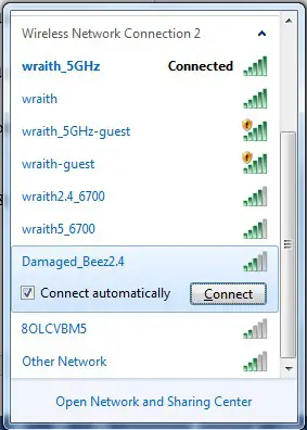
- If you are prompted to enter a network security key, type your password (security key) into the network security key field. Click OK.
- Your computer will connect to the network, and you should be able to access the router.
*Depending on your version of Windows, there could be some differences in wording or icons in these steps.
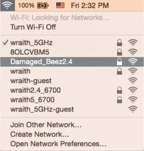
To fix the problem on Mac computers, do the following:
- In the menu bar across the top of the screen, click the Wi-Fi icon. A list of wireless networks will appear.
- In the example below, the computer was connected to another wireless network named wraith_5GHz. The wireless network name of the Linksys E series router, Damaged_Beez2.4 in this example, is shown selected.
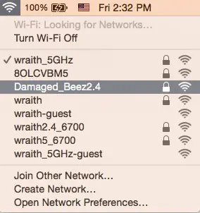
- Click the wireless network name of your Linksys E series router (Damaged_Beez2.4 in the example).
- Type your wireless network password (Security Key) into the Password field. Click OK.
After setup
The internet appears to be unavailable
If the internet has difficulty communicating with your router, the problem may appear as a “Cannot find [internet address]” message in your web browser. If you know that the internet address is correct, and if you’ve tried several valid internet addresses with the same result, the message could mean that there’s a problem with your ISP or modem communicating with your router. Try the following:
- Make sure that the network and power cables are securely connected.
- Make sure that the power outlet that your router is connected to has power.
- Reboot your router.
- Contact your ISP and ask about outages in your area.
The most common method of troubleshooting your router is to turn it off, then back on again. Your router can then reload its custom settings, and other devices (such as the modem) will be able to rediscover the router and communicate with it. This process is called rebooting.
To restart your router using the power cord, do the following:
- Disconnect the power cord from the router and the modem.
- Wait 10 seconds and reconnect the power cord to the modem. Make sure it has power.
- Wait until the modem’s online indicator has stopped blinking (about two minutes). Reconnect the power cord to the router.
- Wait until the flashing green LED between the Reset button and power port is solid. Wait two minutes before trying to connect to the internet from a computer.
Specifications
Linksys E5600
| Model Name | AC1200 Dual-Band WiFi 5 Router |
| Model Number | E5600 |
| Switch Port Speed | 10/100/1000 Mbps (Fast Ethernet) |
| Radio Frequency | 2.4 GHz and 5 GHz |
| # of Antennas | 4 internal |
| Ports | Ethernet (1-4), Internet, Power |
| Buttons | Wi-Fi Protected Setup, Reset, Power Switch |
| LEDs | Power, Internet, Ethernet (1-4) |
| UPnP | Supported |
| Security Features | WPA2 Personal |
| Security Key Bits | Up to 128-bit encryption |
Environmental
| Dimensions | 135mm (L) x 38mm (W) x 185.5mm (H) |
| Unit Weight | 410 g (0.9 lbs) |
| Power | 12V, 1A |
| Certifications | FCC, IC, CE, Wi-Fi (IEEE 802.11 a/b/g/n/ac) |
| Operating Temperature | 32 to 104°F (0 to 40°C) |
| Storage Temperature | -4 to 140°F (-20 to 60°C) |
| Operating Humidity | 10% to 80% relative humidity, non-condensing |
| Storage Humidity | 5% to 90% non-condensing |
Notes:
For regulatory, warranty, and safety information, see the CD that came with your router or go to Linksys.com/support/E5600.
Specifications are subject to change without notice.
Maximum performance derived from IEEE Standard 802.11 specifications. Actual performance can vary, including lower wireless network capacity, data throughput rate, range, and coverage. Performance depends on many factors, conditions, and variables, including distance from the access point, the volume of network traffic, building materials and construction, operating system used, a mix of wireless products used, interference, and other adverse conditions.
BELKIN, LINKSYS, and many product names and logos are trademarks of the Belkin group of companies. Third-party trademarks mentioned are the property of their respective owners. Licenses and notices for third-party software used in this product may be viewed here: http://support.linksys.com/en-us/license. Please contact http://support.linksys.com/enus/gplcodecenter for questions or GPL source code requests.
© 2020 Belkin International, Inc. and/or its affiliates. All rights reserved.
![]()
PANDUAN PENGGUNA
AC1200 ROUTER DUAL-BAND WiFi 5
Model E5600
What’s in this guide
Your Linksys range extender Get started
Setting up as a wireless range extender Setting up as a wired range extender (access point) FAQ
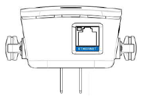
The light on the front of the range extender gives you information about power, updating and signal strength
WPS Button—Use Wi-Fi Protected Setup to automatically and securely add compatible wireless devices to your network with Push Button Connect.
Reset Button—Press and hold until the light on the front of the range extender blinks to reset to factory defaults. (Reset Instructions)
Ethernet Port—Connect wired devices to your wireless network with ethernet (network) cables. The light is green when an ethernet device is connected and active
on this port. The light blinks green when the range extender is sending or receiving data over the port.
Get started
There are two ways to use your Linksys extender: as a wireless range extender or as a wired range extender (access point). Wireless range extenders boost Wi-Fi range for better coverage and increased signal
strength. Wired range extender (access points) create new Wi-Fi hotspots when connected to a router or access point with an ethernet cable. Both scenarios require a router with a working Internet connection.
Before starting setup, decide whether you want to use your RE6300 as a wireless range extender or as a wired range extender (access point). Instructions for both setups are in this guide.
Setting up as a wireless range extender
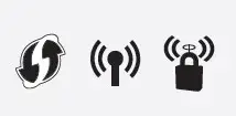
Does your router have a WPS button?
Wi-Fi Protected Setup (WPS) is a simple way to connect Wi-Fi devices with Push
Button Connect. Routers that support WPS have a button that might look like one of these symbols
Yes Continue with Wi-Fi Protected Setup
below No (or not sure) Continue with Browser-based setup on back panel
NOTE — The WPS button will not work if you have disabled WPS on your router.
Wi-Fi Protected Setup (WPS)
- Plug the range extender into an electrical outlet close to your router. You can move the range extender to an ideal location later in step 5. After being plugged in, the indicator light on the front of your range extender will start to blink green for up to a minute
- Wait for the light on the front of your range extender to start to blink orange before going to step 3. This can take up to a minute.
- Extend your 2.4 GHz network.
a. Press the WPS button on your router. Within the next two minutes complete step 3b.
b. Press the WPS button on the side of your range extender. The light on the front of your range extender will blink green.
Watch the light on the front of your range extender to verify whether the connection was successful.
If it turns solid green, the connection was successful. Move to step 4.
If it blinks orange blink orange, the connection failed. You may try again by repeating step 3 or try browser-based setup. - Extend your second network (if you have a dual-band router).
You may skip this step if you have a single-band router or if you don’t want to extend both networks.
a. Press the WPS button on the side of your router again. Within the next two minutes complete step 4b.
b. Press the WPS button on your range extender again. The WPS button will light up and the light on the front of your range extender will start to blink green.
Watch the light on the front of your range extender to verify whether the connection was successful. If it turns solid green, the connection was successful. If it blink orange the connection failed. Try again by repeating step 4. - Move your range extender to an ideal spot.
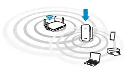
Unplug your range extender and plug it back in midway between your router and the area without Wi-Fi. Using your mobile device or laptop, be sure you have at least two bars (around 50%) of your router’s Wi-Fi signal at that location. If you don’t have two bars, move the range extender closer to the router.
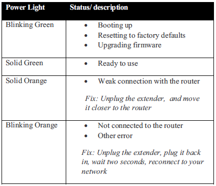
- Check light for connection quality
Check light for connection quality. It can take up to a minute for the ranger extender to start up after moving it. During this period you will see the blinking green light once again.
Solid green Ready to use.
Solid orange Weak connection to the router. Find an outlet closer to your router.
Blinking orange Not connected to the router. Find an outlet closer to your router. - How to connect your Wi-Fi devices to the extended network you just created.
you have set up your range extender with a Linksys Max-Stream Router, give your extended network the same Wi-Fi name and password as your main WiFi to take advantage of seamless roaming.
Connected devices will select the main or extended network as you move around the coverage area.
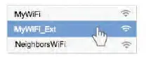
If you do not have a router with seamless roaming, select the extended network on your device’s Wi-Fi manager. Extended networks are identified by “_Ext” added to the end of your main network
name(s). Password(s) will be the same as those for your main network(s).
Your range extender is now set up. Enjoy your extended Wi-Fi coverage.
Accessing your range extender settings after setup
Your range extender’s default admin password is “admin”. It is highly recommended that you change this after WPS setup. To change or view range extender settings, first connect to an extended network.
If your extended network has the same network name as your main network:
- On a computer that is not connected to a wireless network, use an ethernet cable to connect directly to the range extender. Open a browser and go to extender.linksys.com.
OR - Connect to your range extender wirelessly. Depending on your operating system, one of the following links will get you to the login page. Choose one and enter it in your browser. Android and Windows: http://RE6300-XXX Mac OS X or iOS: http://RE6300-XXX.local
NOTE: XXX are the last 3 digits of your range extender’s MAC address. You can find the MAC address on the back of your range extender If your extended network has a different network name than your
main network (for example mywifi_EXT): Connect to the extended network. In a browser, go to http://extender.linksys.com and enter your admin password.
Browser-based setup
- Plug in the range extender.
Plug in the range extender midway between your router and the area without Wi-Fi. Using your mobile device or laptop, be sure you have at least two bars (around 50%) of your router’s Wi-Fi signal at that location. If you don’t have two bars, move the range extender closer to the router. You can move the range extender to an ideal location later using the setup software.
- Wait for the indicator light on the front of your range extender to blink orange. This can take up to a minute.
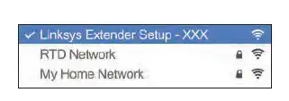
- Connect to range extender setup network.
On a computer, phone or tablet, connect to the Wi-Fi network: Linksys Extender Setup – XXX. (XXX are the last three digits of your range extender’s MAC address.)
- Launch setup
Enter http://extender.linksys.com (or try http://192.168.1.1) in a browser to complete setup. Follow the on-screen instructions to select your network to extend, customize your extended network name and
password and find the best spot using Spot Finder Technology.
- How to connect your Wi-Fi devices to the extended network you just created
If you have set up your range extender with a Linksys Max-Stream
Router, give your extended network the same Wi-Fi name and password as your main WiFi to take advantage of seamless roaming. Connected devices will select the main or extended network as you move around the coverage area. If you do not have a router with seamless roaming, select the extended network on your device’s Wi-Fi manager. Extended networks are identified by “_Ext” added to the end of your main network name(s). Password(s) will be the same as those for your main network(s).
Setting up as wired range extender (access point)
Browser-based setup
- Prepare for setup
Be sure your router has a working Internet connection and you have an ethernet cable long enough to connect the router to the range extender. - Plug the Linksys range extender into a wall outlet
- Wait for the blinking light to change from green to orange.
- Use an ethernet cable to connect the range extender to the LAN port of your router.
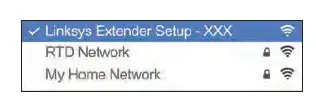
- Connect to the Linksys Extender Setup network. On a computer, phone, or tablet, connect to the Wi-Fi network Linksys
Extender Setup – XXX, where XXX are the last 3 digits of your range extender’s MAC address.
- Launch setup
Enter http://extender.linksys.com (or try http://192.168.1.1) in a browser to complete setup. Be sure to choose “As a wired range extender (access point)” when asked how you want to use your range
extender. Follow the on-screen instructions to create a network name and password for your access point.

- Connect your Wi-Fi devices to the extended network you just created.
Frequently Asked Questions
Why can I not find “Linksys Extender Setup – XXX” in my Wi-Fi list? Make sure the light on the range extender is blinking orange. If you still can’t see the setup network, move the device being used for setup closer to the range extender. Wait for a blinking orange light and refresh the Wi-Fi list.
On browser-based setup, why do I not see the setup screen on http://extender.linksys.com?
On your device’s Wi-Fi manager, make sure “Linksys Extender Setup – XXX” is selected, then refresh your browser.
On browser-based setup, why can I not see my network name on the
“Choose your wireless” page? Your range extender might be too far from the router. Move it closer and refresh the list.
I correctly entered my network password during browser-based setup.
Why does the “Enter your password” page still show an error?
The range extender likely is at the outside limit of the router’s signal. The signal could be getting interrupted before your password makes it to the router. Move your range extender closer to the router and let Spot Finder Technology help you find the ideal location. The further you are from the area in Spot Finder Technology labeled “Just Right” the more likely you are to have issues with your network password.
Why can’t I connect my range extender with WPS?
There are a number of reasons that WPS could fail:
- Your router and range extender are too far apart
- The two-minute connection window expired
- The WPS button on either range extender or router did not depress all the way
- WPS is disabled on the router
- MAC filtering is enabled on the router
How do I reset the range extender to factory defaults? Using a paperclip or safety pin, press the reset button on the side of the range extender and hold until the indicator light starts blinking green.
Why am I experiencing poor signal and slow speed on my
range extender?
Be sure that you’ve placed your range extender in an ideal location, as indicated by Spot Finder Technology. NOTE: When you move around your home, your wireless devices may not disconnect from the router until they lose the Wi-Fi signal. This may occur even if the Wi-Fi signal from the range extender signal is stronger (and vice versa). If you are having connection issues, select the network with the stronger signal.
For advanced configuration, consult the user guide at linksys.com/support/RE6300
Extended network names and passwords
Write down your extended network names and passwords.
Extender admin password
Write down your admin password. You’ll need this if you want to access your range extender settings.
Get Help
Internet: linksys.com/support Twitter: @LinksysCares
Phone (US/Canada): 800-326-7114 (complimentary for 90 days from date of original purchase)
MAX-STREAM™
AC5400 MU-MIMO
GIGABIT ROUTER
Model # EA9500
Product Overview
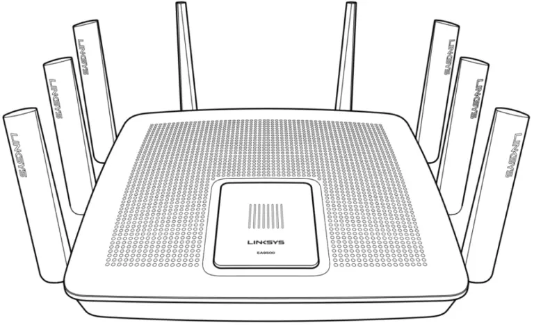
EA9500
Top view

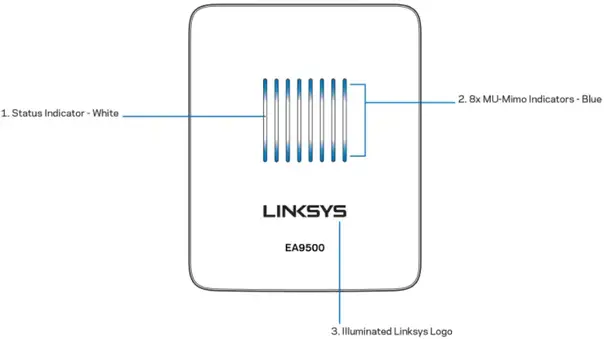
System status indicator
Status Indicator – white (1)—During router startup, stays solid. During router operation, blinks if there is an Internet connection error. Turns off if Wi-Fi is turned off.
MU-MIMO Indicators’ – blue (2)—Pairs of LEDs (above and below status indicator) blink in sequence (left to right) during router startup. Light up, and remain on, in sequence during a firmware update. During router operation, pairs of solid LEDs indicate MU-MIMO devices connected.
*MU-MIMO functionality may require a software/firmware update available at linksys.com/support/ea9500.
Illuminated Linksys Logo—Indicates router is powered on and operational.
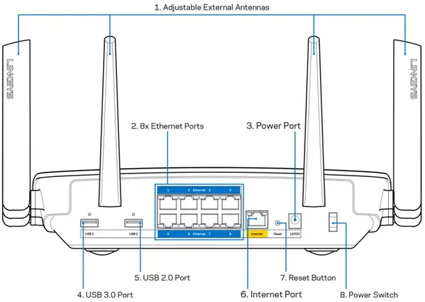
Back view
Adjustable antennas (1)—For best performance, position antennas vertically at a 90-degree angle.
Ethernet ports (2)—Connect Ethernet cables to these blue gigabit (10110011000) ports, and to wired devices on your network.
Note—For best performance, use CAT5e or higher rated cables on the Ethernet ports.
Power port(3)—Connect the included AC power adapter.
USB 3.0 port (4)—Connect and share USB drives on your network or on the Internet.
USB 2.0 port (5)—Connect and share USB drives on your network or on the Internet.
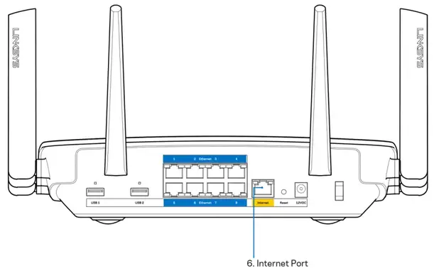
Internet port (6)—Connect an Ethernet cable to this yellow gigabit (10110011000) port, and to a broadband Internet cable/DSL or fiber modem.
Note—For best performance, use CAT5e or higher rated cable on the Internet port.
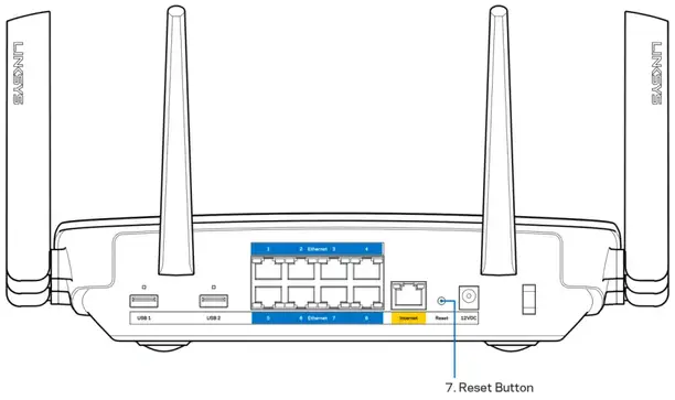
Reset button (7)—Press and hold until the illuminated Linksys logo turns off and blue MU-MIMO indicators start flashing to reset the router to factory settings. You can also restore the factory settings using Linksys Smart Wi-Fi on the Internet or mobile app. (Reset Instructions)
Power switch (8)—Press I (on) to turn on the router.
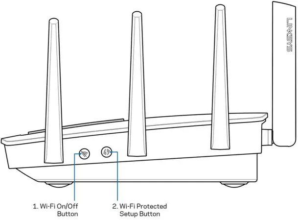
Side view
 Wi-Fl button (1)—Press to turn off wireless networks LED comes on). Press again to turn on wireless networks (LED goes out).
Wi-Fi Protected Setup button (2)—Press to configure wireless security on Wi-Fi Protected Setup-enabled network devices.
Setting Up: Basics
Where to find more help
In addition to this user guide, you can find help at these locations:
- Linksys.com/support/EA9500 (documentation, downloads, FAQs, technical support, live that, forums)
- Linksys Smart Wi-Fi help (connect to Linksys Smart WFFi, then click Help at the top of the screen)
Note—Licenses and notices for third-party software used in this product may be viewed on http://support.linksys.com/en-us/licence. Please contact http://support.linksys.com/en-us/gpcodecenter for questions or GPL source code requests.
How to install your router
- If replacing an existing router, disconnect that router first.
- Turn the antennas up and plug in your router to a power source. Press the power switch to I (on).
- Connect the Internet cable from your modem to the yellow Internet port on your router. Wait until the illuminated Linksys logo is on.
- Connect to the network name shown in the Quick Start Guide that came with your router. (You can change the network name and password later.) Select the option to automatically connect to this network in the future. If you need help connecting to the network refer to your device documentation on the provided CD.
Note —You will not have Internet access until the router setup is complete. - Open a web browser to launch the Linksys Smart Wi-Fi Router setup instructions. If you don’t see the instructions, type http://LinksysSmartWiFi.com in the address bar.
At the end of setup, follow the on-screen instructions to set up your Linksys Smart Wi-Fi account. Use Linksys Smart Wi-Fi to configure your router from any computer with an Internet connection. Manage your router’s settings:
- Change your router’s name and password
- Set up guest access
- Configure parental controls
- Connect devices to your network
- Test your Internet connection speed
Note—As part of Linksys Smart Wi-Fi account setup, you will be sent a verification e-mail. From your home network, click the link in the email to associate your router with the Linksys Smart Wi-Fi account.
Tip-Print the next page, then record your router and account settings in the table below as a reference. Store your notes in a safe place.
| 2.4 GHz Network Name | |
| Network Password | |
| 5 GHz1 Network Name | |
| Network Password | |
| 5 GHz2 Network Name | |
| Network Password | |
| Router Password | |
| 2.4 GHz Guest Network Name | |
| 5GHz Guest Network Name | |
| Guest Network Password (Both guest networks share a password.) | |
| Linksys Smart Wi-Fi Username | |
| Linksys Smart Wi-Fi Password |
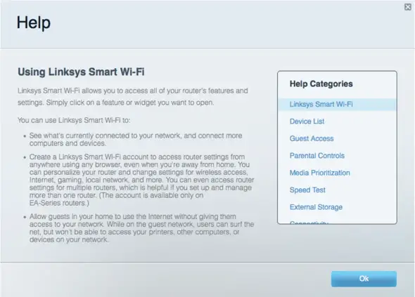
How to Use Linksys Smart Wi-Fi
You can configure your router from anywhere in the world by using Linksys Smart Wi-Fi, but you can also configure your router directly from your home network. Linksys Smart Wi-Fi may be available for your mobile device, as well. See your device’s app store for information.
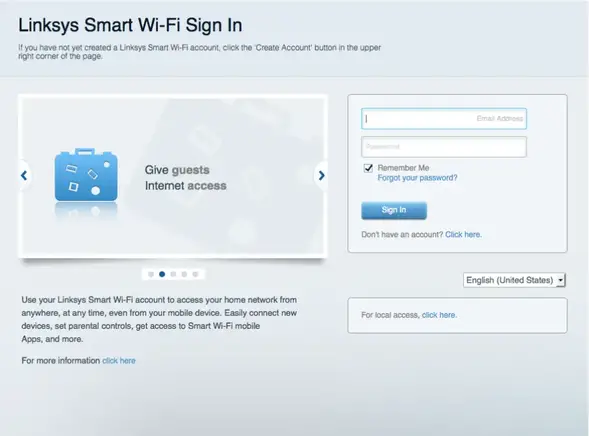
How to connect to Linksys Smart Wi-Fi
To connect to Linksys Smart Wi-Fi:
- Open your computer’s web browser.
- Go to http://LinksysSmartWiFi.com and log in to your account.
If you can’t remember your password, click Forgot your password? and follow the on-screen instructions to recover it.
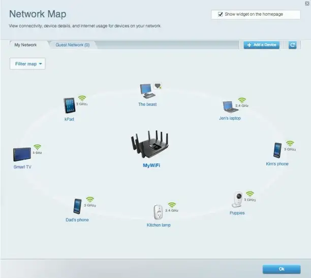
Network Map
Let’s display and manage all network devices connected to your router. You can view devices on your main network and your guest network, or display information about each device.
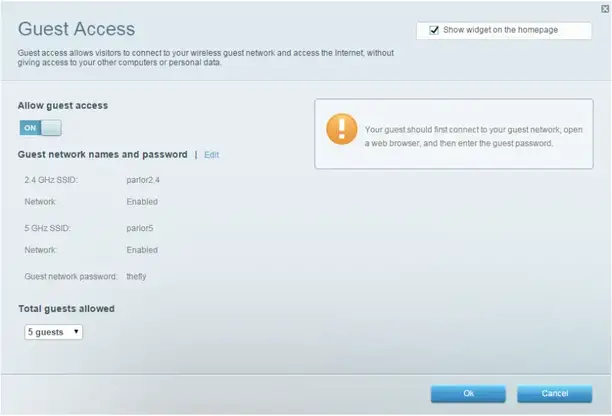
Guest Access
Lets you configure and monitor a network that guests can use without accessing all of your network resources.
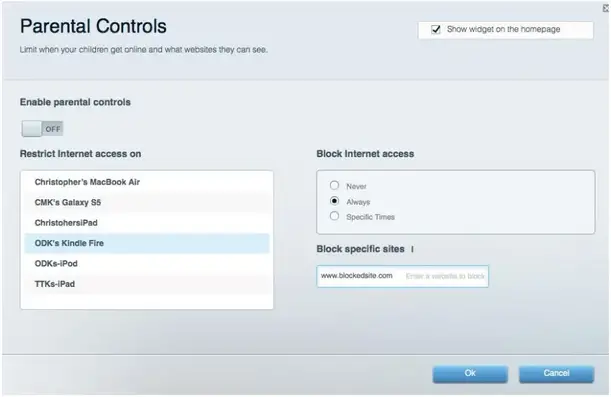
Parental Controls
Let’s block websites and set Internet access times.
Media Prioritization
Lets you set which devices and applications have top priority for your network traffic.
Speed Test
Let’s test your network’s Internet connection speed.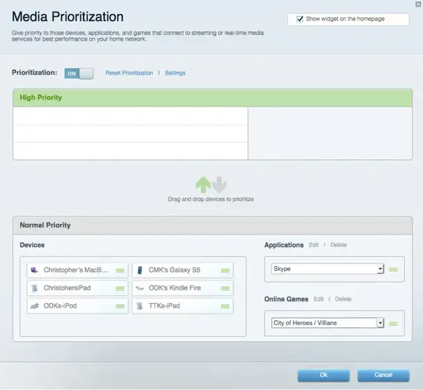
External Storage
Let’s you access an attached USB drive (not included) and set up file sharing, a media server, and FTP access.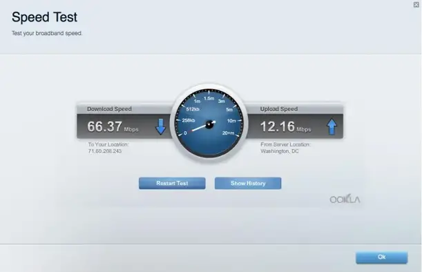
Connectivity
Lets you configure basic and advanced network settings.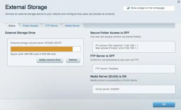
Troubleshooting
Let’s diagnose problems with your router and check the status of the network.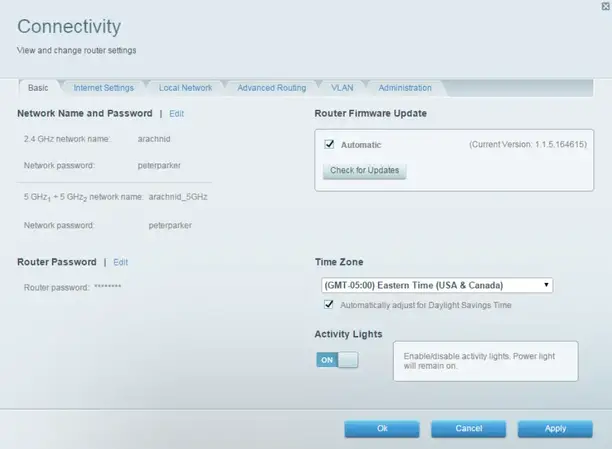
Wireless
Lets you configure your router’s wireless network. You can change network names, security mode, password, MAC filtering, and connect devices using Wi-Fi Protected Setup™.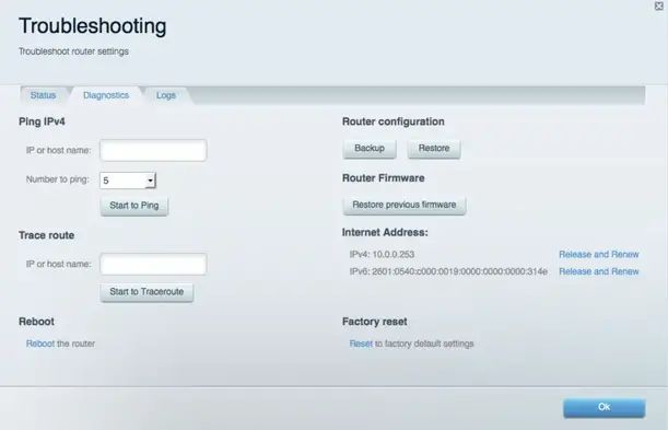
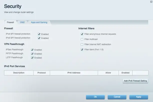
Security
Let’s configure your router’s wireless security. You can set up the firewall, and VPN settings, and make custom settings for applications and games.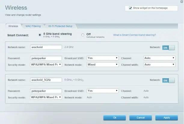
Troubleshooting
You can find more help from our award-winning customer support at Linksys.com/support/EA9500.
Your router was not successfully set up
If Linksys Smart Wi-Fi did not complete the setup, you can try the following:
- Press and hold the Reset button on your router with a paperclip or pin until the illuminated Linksys logo turns off and the blue MU-MIMO indicators start blinking (about 10 seconds). Install the router again.
- Temporarily disable your computer’s firewall (see the security software’s instructions for help). Install the router again.
- If you have another computer, use that computer to install the router again.
If your Internet cable is not plugged in message
If you get a “Your Internet cable is not plugged in” message when trying to set up your router, follow these troubleshooting steps.
- Make sure that an Ethernet or Internet cable (or a cable like the one supplied with your router) is securely connected to the yellow Internet port on the back of the router and to the appropriate port on your modem. This port on the modem is usually labeled Ethernet.
Make sure that your modem is connected to power and is turned on. If it has a power switch, make sure that it is set to the ON or I (as opposed to 0) position.
- If your Internet service is cable, verify that the cable modem’s CABLE port is connected to the coaxial cable provided by your ISP.
- If your Internet service is DSL, make sure that the DSL phone line is connected to the modem’s DSL port.
- If your computer was previously connected to your modem with a USB cable, disconnect the USB cable.
- Install the router again.
Cannot access your router message
To access your router, you must be connected to your own network. If you currently have wireless Internet access, the problem may be that you have accidentally connected to a different wireless network.
To fix the problem on Windows computers, do the following*:
- On your Windows desktop, click on the wireless icon in the system tray. A list of available networks will appear.
- Click your own network name. and Click Connect. In the example below, the computer was connected to another wireless network named wraith 5GHz. The wireless network name of the Linksys EA9500 router, Damaged_Beez2.4 in this example, is shown selected.
- If you are prompted to enter a network security key, type your password (security key) into the network security key field. Click OK.
- Your computer will connect to the network, and you should be able to access the router.
*Depending on your version of Windows, there could be some differences in wording or icons in these steps.
To fix the problem on Mac computers, do the following:
- In the menu bar across the top of the screen, click the Wi-Fi icon. A list of wireless networks will appear. Linksys Smart Wi-Fi has automatically assigned your network a name.
- In the example below, the computer was connected to another wireless network named wraith_5GHz. The wireless network name of the Linksys EA9500 router, Damaged_Beez2.4 in this example, is shown selected.
- Click the wireless network name of your Linksys EA9500 router (Damaged_Beez2.4 in the example).
- Type your wireless network password (Security Key) into the Password field. Click OK.
After setup
The Internet appears to be unavailable
If the Internet has difficulty communicating with your router, the problem may appear as a “Cannot find [Internet address]” message in your Web browser.
If you know that the Internet address is correct, and if you’ve tried several valid Internet addresses with the same result, the message could mean that there’s a problem with your ISP or modem communicating with your router.
Try the following:
- Make sure that the network and power cables are securely connected.
- Make sure that the power outlet that your router is connected to has power.
- Reboot your router.
- Contact your ISP and ask about outages in your area.
The most common method of troubleshooting your router is to turn it off, then back on again. Your router can then reload its custom settings, and other devices (such as the modem) will be able to rediscover the router and communicate with it. This process is called rebooting. To reboot your router using the power cord, do the following:
- Disconnect the power cord from the router and the modem.
- Wait 10 seconds, and reconnect the power cord to the modem. Make sure it has power.
- Wait until the modem’s online indicator has stopped blinking (about two minutes). Reconnect the power cord to the router.
- Wait until the illuminated Linksys logo is on. Wait two minutes before trying to connect to the Internet from a computer.
To reboot your router using Linksys Smart Wi-Fi, do the following:
- Log in to Linksys Smart Wi-Fi. (See “How to connect to Linksys Smart Wi-Fi” on page 9.)
- Under Router Settings, click Troubleshooting.
- Click the Diagnostics tab.
- Under Reboot, click Reboot.
- Click Yes. The router will reboot. While the router is rebooting, all connected devices will lose their Internet connection, and will automatically reconnect when the router is ready again.
Linksys Smart Wi-Fi does not open in your web browser
The latest versions of Google chrome™, Firefox Safari® (for Mac R and iPad®), Microsoft Edge, and Internet Explorer® version 8 and newer work with Linksys Smart Wi-Fi.
Specifications
Linksys EA9500
| Model Name | MAX-STREAM’ AC5400 MU-MIMO GIGABIT ROUTER |
| Model Number | EA9500 |
| Switch Port Speed | 10/100/1000 Mbps (Gigabit Ethernet) |
| Radio Frequency | 2.4 GHz and 5 GHz (x2) |
| # of Antennas | 8 external adjustable antennas |
| Ports | USB 2.0, USB 3.0, Ethernet (1-8), Internet, Power |
| Buttons | Wi-Fi, Wi-Fi Protected Setup, Power, Reset |
| LEDs | Top panel: Status Indicator, MU-MIMO Indicators, illuminated Linksys logo Side panel: Wi-Fi, Wi-Fi Protected Setup Back panel: USB 1, USB 2, Ethernet (1-8), Internet |
| UPnP | Supported |
| Security Features | WEP, WPA2, RADIUS |
| Security Key Bits | Up to 128-bit encryption |
| Storage File System Support | FAT, NTFS, and HFS+ |
| Browser Support | Latest versions of Google Chrome’, Firefox®, Safari® (for Mac® and iPad), Microsoft Edge, and Internet Explorer® version 8 and newer work with Linksys Smart Wi-Fi |
Environmental
| Dimensions | 264.52 mm x 318.15 mm x 66.66 mm |
| Unit Weight | 1727.7 g |
| Power | 12V, 5A |
| Certifications | FCC, IC, CE, Wi-Fi (IEEE a/b/g/n/ac), Windows 7, Windows 8 |
| Operating Temperature | 32 to 104°F (0 to 40°C) |
| Storage Temperature | -4 to 140°F (-20 to 60°C) |
| Operating Humidity | 10% to 80% relative humidity, non-condensing |
| Storage Humidity | 5% to 90% non-condensing |
Notes:
For regulatory, warranty, and safety information, see the CD that came with your router or go to Linksys.com/support/EA9500. Specifications are subject to change without notice. Maximum performance derived from IEEE Standard 802.11 specifications. Actual performance can vary, including lower wireless network capacity, data throughput rate, range, and coverage. Performance depends on many factors, conditions, and variables, including distance from the access point, the volume of network traffic, building materials and construction, operating system used, a mix of wireless products used, interference, and other adverse conditions.
BELKIN, LINKSYS, and many product names and logos are trademarks of the Belkin group of companies. Third-party trademarks mentioned are the property of their respective owners. Licenses and notices for third-party software used in this product may be viewed here: http://support.linksys.com/en-us/license. Please contact http://support.linksys.com/en-us/gplcodecenter for questions or GPL source code requests.
© 2016 Belkin International, Inc. and/or its affiliates. All rights reserved.
LINKSYS 800WS Flash Unit
GENERAL SAFETY INFORMATION
Paul C. Buff Flash Units are designed for professional photography use. As with all electronic equipment,
users must observe all warnings and safety precautions. Carefully read all operating instructions and safety instructions before use.
WARNING! HIGH VOLTAGE! Flash units contain internal components that can store dangerously high voltages, even when the units are unplugged. Batteries should not be exposed to excessive heat (i.e. direct sunlight, open flame, etc.)
GENERAL PRECAUTIONS
- Do not operate a flash unit on or around flammable materials.
- Keep the unit away from fire, flames, and heated surfaces.
- Do not insert any foreign objects into any ventilation holes. Do not carry or store a flash unit together with necklaces, hair pins, nails, paper clips, or any other small metal objects.
- Do not cover the unit during operation. Air circulation must be permitted. Do not obstruct ventilation holes by covering the unit while in use or by operating from inside a carrying bag.
- Do not operate or store a flash unit in or around water. High voltage equipment can cause electric shock when operated in or near water. Your flash unit should only be used in dry, moderate conditions where the equipment is protected from rain, dirt, sand and dust.
- Do not use ungrounded power cords, power outlets or power strips. Paul C. Buff, Inc. Flash Units may only be connected to 3-wire grounded AC outlets to avoid shock hazard. Do not connect the unit to an ungrounded outlet or to a two-wire extension cord or adapter that eliminates the ground prong. Do not use any cords that have been damaged.
Paul C. Buff, Inc. flash units contain no user-serviceable parts.
Never open, disassemble, or attempt to repair any components. Only qualified technicians should service the system as incorrect disassembly can create an electric shock hazard. Fingers and other foreign objects must never be inserted or dropped inside any of the vents. If the unit has been dropped or damaged, discontinue use and contact customer service. Do not attempt to make any changes or modifications as any modifications made, outside of those performed or approved by Paul C. Buff, Inc., may present hazardous conditions and void the warranty. The only user-replaceable components are the flashtube, cover, and stand mount.
NOTE – RADIO FREQUENCY ENERGY
The LINK 800WS Flash Unit features a built-in CyberSync transceiver. This unit makes use of the radio spectrum and emits radio frequency energy. Interference can be a factor, as the frequency used is shared with other users and electronics. Please adhere to local regulations when using this device.
WHAT’S INCLUDED:
(1) LINK Flash Unit
(1) AC Power Cord
(1) Gel Diffusion Dome
(1) 14mm Flash Tube
(1) Shipping Cover
ADDITIONAL ITEMS AVAILABLE:
LINK Battery | LINK Battery Charger | HUB Remote | Color Gel Diffusion Domes
GETTING STARTED
STAND MOUNT
The stand mount is made of aluminum and features a locking handle, and two knobs. The smaller knob is what attaches the stand mount to the stud of your light stand. The larger knob connects directly to the locking handle and allows you to control and secure the tilt position of the flash unit.
PLACING THE LINK ON A LIGHT STAND
The unit arrives with the stand mount tucked under the unit. To release, open the locking handle by pulling out and loosening the large knob by turning counter-clockwise. The stand mount will then move freely. Place the open collar at the base of the stand mount over the stud mount on your light stand. Tighten the small knob, by turning clockwise, to secure. Tighten the large knob, by turning clockwise, while holding the locking handle with your flash unit at your desired angle. Once satisfied with its placement, push the locking handle in towards the stud mount to secure. To readjust the tilt, simply pull the handle outwards from the stand mount, reposition your flash unit, and then push the locking handle in towards the stud mount to secure the placement. Make sure that the unit is secure prior to releasing.
SHIPPING COVER
The shipping cover is made of aluminum and provides protection to the flash tube when transporting or storing your flash unit. You MUST remove the shipping cover prior to turning on the flash unit.
REMOVE THE SHIPPING COVER
To remove the shipping cover, slide either of the quick-release levers to retract the four faceplate fingers holding the cover.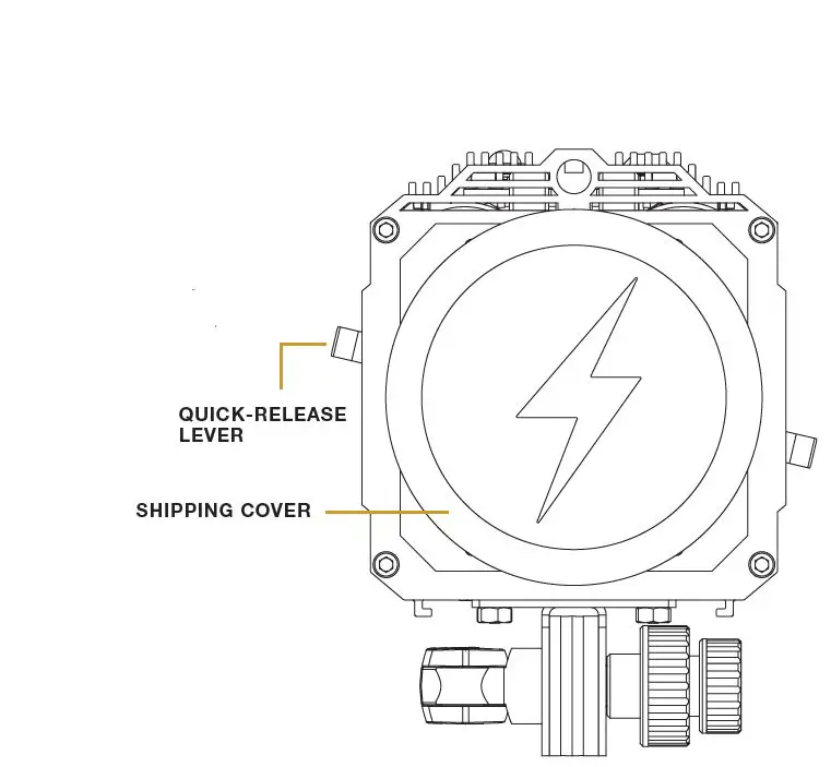
FRONT VIEW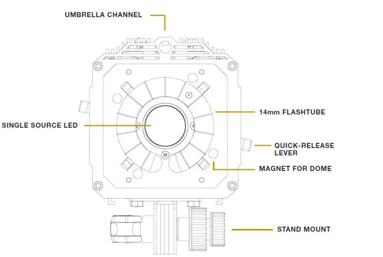
ATTACHING MODIFIERS
QUICK-RELEASE LEVER and HOLDING FINGERS
The LINK faceplate utilizes a Balcar mount that has four holding fingers, controlled levers. These holding fingers expand and retract to hold various reflectors as well attachment. The LINK is compatible with all Paul C. Buff, Inc. modifiers.
UMBRELLA CHANNEL
Located above the faceplate, the umbrella channel is outfitted with internal tension clips to hold an umbrella or PLM in place without any slipping or drooping. The umbrella channel can fit up to a 9mm rod.
MAGNETIC ATTACHMENT
New to the Paul C. Buff, Inc. line of flash units is a magnetic attachment connection for difussion included with the unit), creative color, and color correcting silicone domes (both sold separately).
POWERING YOUR UNIT
AC INPUT
The AC input is located at the bottom of the unit. The LINK flash unit offers global plug-and-play with automatic power switching that allows the unit to operate on power lines from 95 to 265 VAC, 50 or 60 Hz, automatically sensing the voltage / frequency and adjusting accordingly with no user attention required. For use in North America, the unit arrives with a 15-foot power cord that has a standard IEC connector on one end and a grounded, three-pronged male plug on the other. This power cord connects to the flash unit on its back control panel and is then plugged into a suitable 120 Vac, 50-60 Hz grounded power outlet.
BATTERY
The LINK can be powered using a proprietary battery. For more information see page 9.
BACK PANEL DISPLAY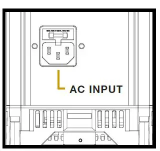
POWERING THE UNIT ON / OFF
Press and hold the POWER button for two seconds. When the LINK is powered off, the current settings are stored and will apply when the flash unit is powered on again. *To reset the LINK to factory settings, PRESS AND HOLD the POWER and TEST buttons simultaneously for 10 seconds.
DEFAULT SETTINGS
The LINK flash unit will default to the following settings:
FLASH: – COLOR MODE at -4.0
MODEL: – TRACK MODE at -4.0
SYNC MODE: – REMOTE
FREQUENCY (FREQ): – 1
CHAN: – 1
READY INDICATOR: – Visual and Audio
*When operating off battery power, the MODEL MODE will ALWAYS default to OFF. The segment that is blinking is the current segment that you are in. For general usage, and optimal light output efficiency, it is recommended to use the LINK at your camera’s max sync speed or lower.
NAVIGATING THE BACK PANEL
The unit DEFAULTS to FLASH MODE. You can quickly short press on the rotary dial to switch between FLASH and MODEL segments, for easy power adjustment. When in FLASH or MODEL SEGMENT, simply turn the rotary dial clockwise to increase the power, and turn the rotary dial counter clockwise to decrease the power.
PRESS AND HOLD the rotary dial to enter the selection menu. The segment that you are in will blink.
ROTATE THE DIAL to navigate between the available options in each segment. (i.e. choosing between ACTION, COLOR, HSS, and OFF in FLASH MODE) or to increase/decrease the power for the flash or modeling light, respectively.
SHORT PRESS in on the rotary dial to confirm your selection AND to move to the next segment.
EXIT THE SEGMENT you are in and return to the FLASH segment, by pressing and holding the rotary dial for 2 seconds.
IF NO ACTION IS MADE, the unit will revert to the FLASH segment after 10 seconds and will keep whatever setting is highlighted at time out.
FLASH MODES
COLOR MODE
In Color Mode, the LINK maintains color consistency to +/- 150°K throughout the entire power range. Color mode is also the factory default and is best for creating standard portraits.
ACTION MODE
In Action Mode, the unit’s flash duration gets shorter as power is reduced. Flash duration is basically a measurement of the burn off time of the flash once it is fired. The shorter the flash duration, the crisper your action shots in studio will be. Action mode is best utilized when stopping action (water splashes, dancer’s jumping, etc.) when you are in an environment where you have full control over your ambient light.
HSS MODE
High speed sync (HSS) mode is different from Action Mode in that it allows you to exceed your camera’s max sync speed with studio flash. The LINK can sync up to 1/8000s with compatible cameras. HSS MODE is necessary when you wish to exceed your camera’s sync speed. In HSS MODE the flash will pulse throughout the duration of the image being taken so that the full frame is exposed properly and no banding will occur. HSS is used primarily in outdoor situations where you are looking to capture movement,
or achieve a very shallow depth of field, and the ambient light is unable to be controlled.
TTL MODE
TTL Mode allows for automatic brightness adjustment for subjects who move rapidly towards and away from the flash unit, or in situations where the conditions are rapidly changing.
OFF The flash modes can all be turned off if you want to only use the modeling light.
MODEL MODES
FULL
The modeling light stays at FULL POWER regardless of the flash output.
TRACK
The modeling light tracks the flashpower output, brightening or dimming automatically as the flashpower is adjusted up or down.
ADJUST (ADJ)
The modeling light output can be adjusted independently from the flash output.
OFF
The model modes can all be turned off if you are wanting to only use the modeling light.
MODELING LIGHT FOR VIDEO USE
Offering an 800W equivalent LED, the LINK pairs a brighter light with a quiet fan, for those doing video work. Color correction domes are available (separately) in both FULL and HALF CTO.
SYNC MODES
SLAVE
The slave eye is on, causing the LINK unit to flash simultaneously whenever it “sees” the flash from another unit (still active whether or not the sync jack is in use).
REMOTE
This setting activates the internal CyberSync Transceiver. Additionally, you can set the LINK to REMOTE when utilizing the CSXCV and PocketWizard MC2 port at the top of the unit.
When using a PocketWizard MC2 the FREQ and CHAN segments will be empty. To make adjustments to the ZONE, CONTROL, and CHANNEL segments for the PocketWizard, complete the following steps:
PRESS AND HOLD the rotary dial to enter the selection menu. The segment that you are in will blink.
SHORT PRESS in on the rotary dial to confirm your selection AND to move to the next segment. Following the SYNC segment, the LINK will then provide the appropriate PocketWizard fields beginning with “2on” for ZONE, followed by “ctl” for CONTROL, and lastly “ch” for CHANNEL.
ROTATE THE DIAL to navigate between the available options in each segment.
SHORT PRESS in on the rotary dial to confirm your selection AND to move to the next segment.
SLAVE / REMOTE Both SLAVE and REMOTE are activated.
NONE
Set to NONE when plugging into the SYNC JACK for firing the unit.
FREQUENCY
The frequency (FREQ) ranges from 1 – 16. Each flash unit in your setup should all be set to the same frequency, so that they all fire together.
CHANNEL
The channel (CHAN) ranges from 1 – 16. Each flash unit in your setup should be set to its own individual channel so that it can be controlled independently from each light in your setup. The CHAN is only necessary when using the CyberSync remote system (i.e. CyberCommander, CyberSense, or BUFF App).
RECYCLE / READY INDICATOR
Recycle indication is provided by an audible beep and by the modeling lamp dimming during recycle, then restoring brightness when recycle is complete. These can be set to be used separately or in conjunction with one another. It can also be set to OFF if no indication is desired.
BATTERY INDICATOR
The BATTERY segment is not accessible via the rotary dial and is only used to visually indicate battery life. This segment will be EMPTY when no battery is connected.
LINK BATTERY
INSTALLING THE BATTERY
The battery, sold separately, slides into the channel on the underside of the unit, covering the AC input, and locking into place.
BATTERY LIFE INDICATOR
The battery life is indicated by the small lights on the rear of the battery and are illuminated when the button is pushed.
A fully charged battery will provide approximately 250 full power flashes before needing to be recharged. The LED modeling light of the LINK can be powered via the battery however, be aware if running at full power the battery will last about 45 min. (assuming no flash use during this time).
REMOVING THE BATTERY
The battery can be removed from the LINK by pressing down on the tab and sliding out from the channel. It is recommended to remove the battery prior to transporting or storing the LINK.
EXPECTED LIFETIME
The battery should last between 2 – 3 years under normal use.
MAINTAINING THE BATTERY
If you aren’t going to use the battery for an extended period of time (>3 months) it is best to leave the batteries partially discharged (40-60% of full charge) rather than fully charged.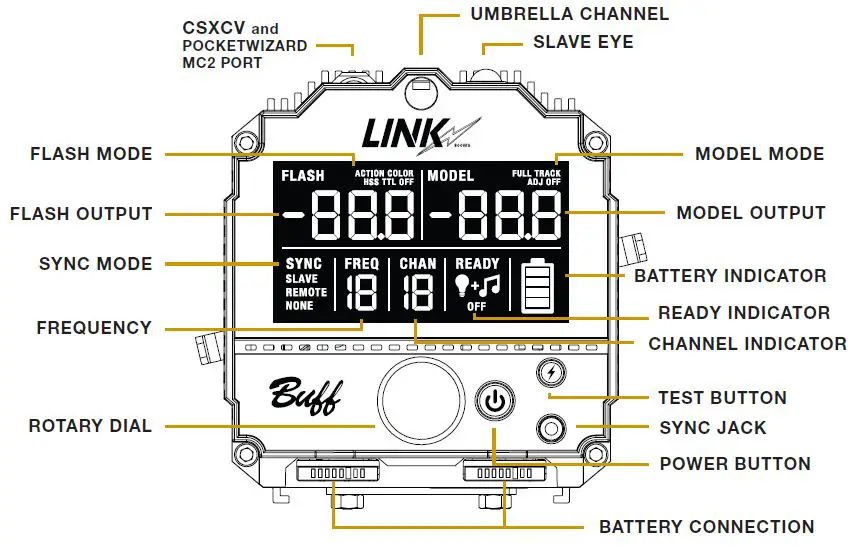 CHARGING THE BATTERY
The battery charger, sold separately, can charge up to two LINK batteries consecutively. The charger has indicator lights notifying what charging state the battery is in. When two batteries are charging, one will charge fully, and then the second will begin to charge. It takes approximately 90 min. for a depleted battery to be charged to full.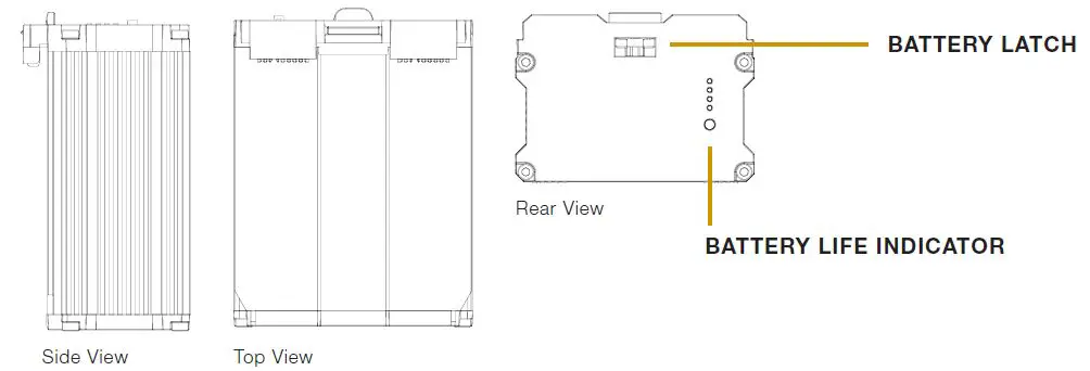
HUB REMOTE
The HUB remote (sold separately) is a new addition to our CyberSync remote system. It provides all of the necessary communication between the camera and the LINK to trigger the flash unit. While it is camera specific for usage of TTL and HSS, the HUB will function as a standard trigger similar to our CyberSync Trigger Transmitter and can be used with any camera brand. 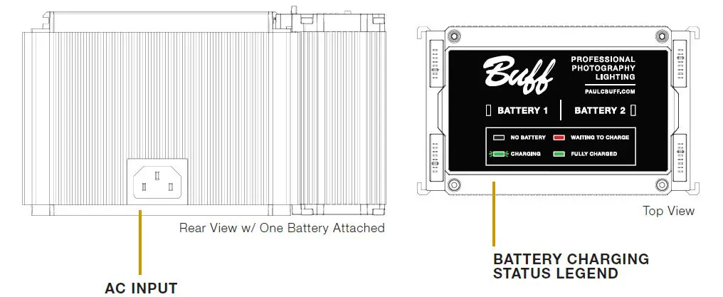
ATTACHING THE HUB TO YOUR CAMERA
Slide the bottom of the HUB onto your camera’s hot shoe. Turn the locking wheel clockwise to lock the HUB on to your camera.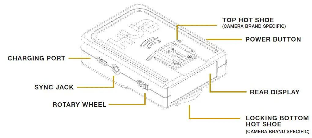
POWERING THE HUB ON / OFF
Press and hold the POWER button, located on the right side of the HUB, for two seconds.
REAR DISPLAY
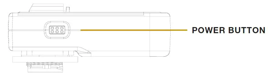
BLUETOOTH
By default, BLUETOOTH is ON when the HUB is first activated. To turn BLUETOOTH ON or OFF, turn the ROTARY WHEEL until BLUETOOTH appears on the display. Press in on the ROTARY WHEEL to enter the BLUETOOTH section. Turn the ROTARY WHEEL to toggle between ON and OFF. Press in on the ROTARY WHEEL to confirm your selection.
SETTING THE FREQUENCY
The FREQUENCY ranges from 1 – 16. To set the frequency turn the ROTARY WHEEL until FREQUENCY appears on the display. Press in on the ROTARY WHEEL to enter the FREQUENCY section. Turn the ROTARY WHEEL until your desired frequency appears. Press in on the ROTARY WHEEL to confirm your selection.
SENDING A TEST FIRE
Press in on the rotary wheel, located on the left side of the HUB. This will send a test fire to any flash units that are on the same frequency.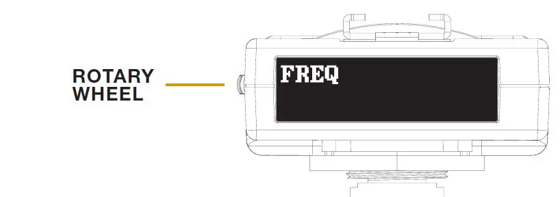
TTL MODE
To set the HUB into TTL mode, turn the ROTARY WHEEL until TTL appears on the display. Press in on the ROTARY WHEEL to enter the TTL section. Turn the ROTARY WHEEL to toggle between TTL and MAN (for manual). Press in on the ROTARY WHEEL to confirm your selection.
HSS MODE
The HUB will enter HSS mode automatically when your camera is set above it’s max sync speed. The HUB will also superseed any settings found on the LINK. For example, if the LINK is set to COLOR MODE but you are now shooting above your camera’s max sync speed, the HUB will then adjust the LINK and place it into HSS MODE.
CHANGING THE DISPLAY BRIGHTNESS
Using the ROTARY WHEEL, scroll three times so that BRIGHTNESS appears on the display. Then, press in on the ROTARY WHEEL. To adjust the brightness scroll using the ROTARY WHEEL until you have reached your desired brightness level. Press in on the ROTARY WHEEL to safe your setting. 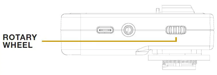 CHARGING THE HUB
To charge the HUB plug the USB-C side of the included charging cable directly into the HUB. Then plug the USB-A side into a wall outlet connector.
GENERAL INFORMATION
| Watt seconds | 800 Ws |
| Action Mode – Power Variability | 9 f-stops (full to 1/256 power) |
| Color Mode – Power Variability | 9 f-stops (full to 1/256 power) |
| HSS Mode – Power Variability | 9 f-stops (full to 1/256 power) |
| Recycle to Full | 3.5 sec. |
| Flash Duration (t.5) – in Action Mode | 1/1,400 sec. (at full power) | 1/42,000 sec. (at min. power) |
| Flash Duration (t.1) – in Action Mode | 1/470 sec. (at full power) | 1/18,600 sec. (at minimum power) |
| Flash Duration (t.5) – in Color Mode | 1/1,400 sec. (at full power) | 1/8,200 sec. (at minimum power) |
| Flash Duration (t.1) – in Color Mode | 1/430 sec. (at full power) | 1/5,500 sec. (at minimum power) |
| Power Requirements | Input Power: 95 – 265VAC, 50/60Hz |
| Average Current Draw | 4.5 amps |
| Internal Receiver Range (from rear of unit) | Front: 175’ | Right: 290’ | Left: 325’ | Rear: 310’ |
| Sync / Trigger Voltage | Less than 5 volts (safe for use with DSLR cameras) |
| Modeling Lamp | 800 W Equivalent Daylight-Balanced |
| Modeling Lamp Fan Audibility | 35dBA (650w equivalent) |
| LUX at 6’ with bare bulb | 320lx |
| LUX at 6’ with diffusion dome | 230lx |
| LUX at 6’ with diffusion dome and 8.5HOR | 600lx |
| LUX at 3’ with bare bulb | 1280lx |
| LUX at 3’ with diffusion dome | 920lx |
| LUX at 3’ with diffusion dome and 8.5HOR | 2400lx |
| Flashtube | 14mm single-ring flashtube (daylight-balanced and UV-coated) |
| LCD Display | 3.5” display |
| Stand Mount | Fits stands up to 5/8 in. |
| Umbrella Mount | Accepts umbrella rods up to 9mm |
| Weight | 7 lbs. 8 oz. |
| Weight with Battery | 8 lbs. 11 oz. |
| Dimensions | 6.5 in. (height) x 4.875 in. (diameter) x 12.625 in. (length) |
BUFF APP
The ‘BUFF App’ is available for both iOS and Android users. The app works in conjunction with the HUB remote and allows a user to control their lighting setup directly from their phone. Adjust the flash and model output, turn lights on and off in your setup, and more! The app also processes all firmware updates for the LINK, when they are available. Additional features to be added in future versions.
FREQUENTLY ASKED QUESTIONS
GENERAL QUESTIONS
Does the placement of the battery cause an issue with too much weight being on the back?
If the handle on the light stand is not stiff enough, the LINK will lean backwards under the weight of the battery, or fowards under the weight of a modifier (softbox, octabox, umbrella). To remedy this, simply pull out the handle of the light stand to loosen it, turn the large knob clockwise to tighten the final retention force and then pull in the handle of the light stand to re-tighten it.
What is the usable HSS range?
9 stops (full to 1/256 power)
MODELING LIGHT
Is the LED single source? Yes.
What is the CRI measurement? 90
What is the TLCI measurement? 93
What is the lumen measurement? 12,000
What is the actual wattage of the LED?
Running on AC: 95W | Running on battery: 85W
This does not affect the brightness, and is simply more efficient on battery power.
What is the LUX measurement?
Lux is not a measurement of the output of a light source. Lux describes how much light is shining on a surface. It is dependent on three things:
- The amount of light emitted by a source.
- The distance between the light source and the measurement surface.
- The surface area of the measurement surface It is highly context dependent and cannot be specified up-front.
VIDEO USE | LED Modeling Light and Fan Information
What is the decibel measurement of the fan with the LED modeling light at full power? 35dBA
What is the watt equivalent of the LED modeling light at full power?
The LED modeling light at full power emits the equivalent amount of light as a 600W Halogen bulb or a 800W Incandescent bulb.
BATTERY
How long will the battery last with the modeling light at full power (no flash)?
Approx. 60 minutes How many full power flashes on a fully charged battery (without the LED on)?
250
What is the expected lifetime of the battery before needing to be replaced?
2-3 years
Does the charger charge the two batteries consecutively or at the same time?
Consecutively
How long does it take for one battery to fully charge from depletion?
90 minutes
Will the LINK work with the Vagabond Mini?
No. The LINK draws more power than the Vagabond Mini is capable of supplying.
Will the LINK work with the Vagabond Extreme or the Vagabond 2?
Yes. The maximum output of the inverter must be 400W or greater. Pure sine wave is preferred but modified sine wave will also work. ABSOLUTELY DO NOT USE A SQUARE WAVE INVERTER!
Are there any best practices for storing and/or maintaining the life of the battery?
- Avoid over-discharging the battery (i.e. using the battery until the LINK shuts down, wait a few minutes for the battery to recover a bit and then continuing to use the battery until every last Joule is extracted). Repeated complete discharges can cause induce errors in the BMS circuitry that will prevent the battery from fully recharging.
- If you aren’t going to use the battery for an extended period of time (>3 months) it is best to leave the batteries partially discharged (40-60% of full charge) rather than fully charged. When a Lithium-Ion battery is fully charged, it will oxidize much faster, which reduces its useful life.
**The LINK battery (purchased separately) arrives with a 1-Year Factory Warranty.**
WARRANTY INFORMATION
The LINK 800WS flash unit arrives with our 60-Day Absolute Satisfaction Guarantee. If you are not satisfied with the system for any reason, you may return it within 60 days for a complete refund, minus the cost of shipping. In order to receive your full refund, ensure that all items originally arriving with the system are included in your return.
The unit also arrives with our 2-Year Factory Warranty. Paul C. Buff, Inc. guarantees to the original purchaser an individual product factory warranty against manufacturer defects in materials and workmanship, beginning with the date that the product is originally shipped to the customer.
Terms and Conditions of Warranty:
- This warranty is limited to the repair or replacement of a product or component that should become defective under normal use, as outlined in the product description and product manual.
- If, during the applicable warranty period, the product is found to be defective by Paul C. Buff, Inc., we will repair or replace the defective component without charge for labor or parts.
- This warranty will not cover deterioration or malfunction resulting from accident, act of nature, abuse, misuse, neglect, unauthorized product repair, shipping of the product, opening of or modification or failure to follow instructions supplied with product.
- This warranty does not apply to any flashtubes, modeling lamps, or batteries, that may arrive with a product as these become exhausted based on normal use.
- The product must be returned to Paul C. Buff, Inc. for warranty service. For customers in the United States, warranty service includes return shipment via FedEx. Customers outside of the United States will be responsible for all shipping fees, duties, taxes and brokerage fees to ship the product to and from our offices.
- Paul C. Buff, Inc. IS NOT RESPONSIBLE FOR ANY SPECIAL, INCIDENTAL, INDIRECT, PUNITIVE OR CONSEQUENTIAL DAMAGES, LOST PROFITS, OR PRODUCTS LOST, STOLEN OR DAMAGED DURING SHIPPING, WHETHER ARISING IN CONTRACT, TORT (INCLUDING NEGLIGENCE), OR OTHERWISE. ALL LIABILITY OF Paul C. Buff, Inc. SHALL BE LIMITED TO THE REPAIR OR REPLACEMENT, AT OUR OPTION, OF ANY DEFECTIVE PRODUCT.
If you have questions about the guarantee or warranty, please contact our customer service team via phone at 1.800.443.5542 or 615.383.3982. We are available Monday through Friday, from 9:00 am to 5:00 pm, CT. You may also email our customer service team at [email protected].
For more information on our products and the various accessories that are compatible with the LINK 800WS flash unit, visit our website at www.paulcbuff.com.
FCC INFORMATION
NOTE: This equipment has been tested and found to comply with the limits for a Class B digital device, pursuant to part 15 of the FCC Rules. These limits are designed to provide reasonable protection against harmful interference in a residential installation. This equipment generates, uses and can radiate radio frequency energy and, if not installed and used in accordance with the instructions, may cause harmful interference to radio communications. However, there is no guarantee that interference will not occur in a particular installation.
If this equipment does cause harmful interference to radio or television reception, which can be determined by turning the equipment
off and on, the user is encouraged to try to correct the interference by one or more of the following measures:
- Reorient or relocate the receiving antenna.
- Increase the separation between the equipment and receiver.
- Connect the equipment into an outlet on a circuit different from that to which the receiver is connected.
- Consult the dealer or an experienced radio/TV technician for help.
Warning: Changes or modifications to this unit not expressly approved by the part responsible for compliance could void the user’s authority to operate the equipment.
FCC Radiation Exposure Statement
The device has been evaluated to meet general RF exposure requirement. The device can be used in fixed/mobile (min 20cm) exposure condition without restriction.
This device complies with part 15 of the FCC Rules. Operation is subject to the following two conditions:
- This device may not cause harmful interference, and
- this device must accept any interference received, including interference that may cause undesired operation.
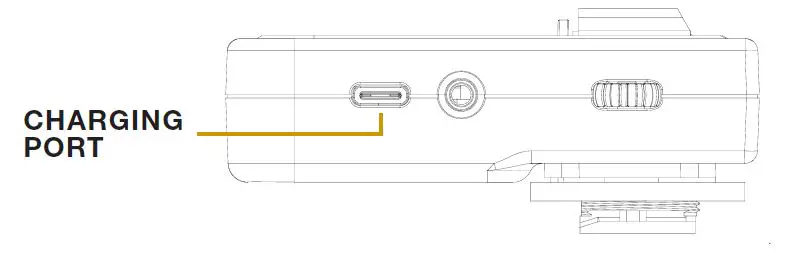
Modem InformationDOCSIS 3.0 Dual Band AC 1900 WiFi Modem 24×8 channel bonding To achieve Gigablast or Ultimate Classic speeds, a DOCSIS 3.1 modem is required |
Highest Service LevelUltimate 500 |
Front View
|
After the cable modem is successfully registered on the network, the Power, Receive, Send, and Status indicators illuminate continuously to indicate that the cable modem is online and fully operational. | |
Back View
|
The modem includes the following connection ports:
|
|
MAC Address
|
The information below is usually found on a sticker located on the bottom of the modem.
|
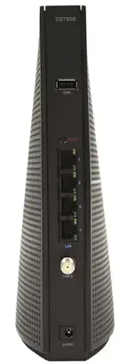

Troubleshooting
The lights indicate the current status of your device. To troubleshoot any connection problems, use the table below.
| Modem Light | Status | Problem |
|---|---|---|
| Power | On | Lights up green when the modem router is powered on. |
| Off | No power. Verify power supply connections and electrical outlet. Ensure the outlet is not connected to a switch. Press the Power ON / OFF button on the back of the modem to ensure it is turned on. | |
| Receive | Solid Blue | Light is solid blue during multichannel bonding. |
| Solid Green | Light is solid green when the modem router is receiving data from the cable network. | |
| Blinking | Light blinks green while the modem router is searching for a connection over the cable network. | |
| Send | Solid Blue | Light is solid blue during multichannel bonding. |
| Solid Green | Light is solid green when the modem router is sending data to the cable network. | |
| Blinking Green | Light blinks green while the modem router is searching for a connection over the cable network. | |
| Off | No upstream channels are in use. – Verify all cable connections and try resetting the modem. | |
| Status | On | Lights up green when the modem router has an internet connection. |
| Blinking | Flashes green while the modem router is establishing the internet connection. | |
| Off | The modem is Offline. Verify all cable connections and try resetting the modem. | |
| 2.4 GHz | On | Light is solid green when broadcasting 2.4 GHz signal. |
| Blinking | Light blinks when the modem router is actively sending or receiving data over the network. | |
| Off | No device is connected or the device is disabled. Verify all cable connections and try resetting the modem. | |
| 5 GHz | On | Light is solid green when broadcasting 5 GHz signal. |
| Blinking | Light blinks when the modem router is actively sending or receiving data over the network | |
| Off | No device is connected or the device is disabled. Verify all cable connections and try resetting the modem. | |
| USB | On | Light is solid green when the modem router is connected to a device through the USB port. |
| WPS | On | Light is solid green when a Wi-Fi Protected Setup™ connection is successfully established. |
| Blinking | Light blinks slowly while WPS is setting up a connection, and blinks rapidly if an error occurs. | |
| Off | Light is off when WPS is idle. |
Manufacturer Resources
For more detailed technical information on the Linksys CG7500, refer to the following.
- Linksys_CG7500_Data_Sheet_LNKPG-00372_RevA00 [PDF]
- Linksys_CG7500_QSG_Draft_B00 [PDF]
- Linksys_CG7500_User_Guide_Draft_A00 [PDF]
Leave a comment
Cancel reply
]]>
Modem InformationCable Modem DOCSIS 2.0 with speeds of up to 25 Mbps on a wired connection. Cox recommends a DOCSIS 3.0 16×4 or higher modem What does this mean? |
Highest Service LevelStarter |
Front View
|
After the cable modem successfully registers on the network, the Power, Cable, and USB or Ethernet indicators illuminate continuously to indicate that the cable modem is online and fully operational. | |
Back View
|
The Linksys BEFCMU10v4 has the following ports available on the back of the modem.
The RESET button is for maintenance purposes only. |
|
MAC Address
|
MAC addresses are written as 12 digits containing both letters and numbers (0-9, A-F). A MAC address is unique. The first six characters of the MAC address are unique to the manufacturer of the device. |


Troubleshooting
The modem lights indicate the current status of your cable modem. To troubleshoot any connection problems, use the table below.
| Modem Light | Status | Problem |
|---|---|---|
| Power | Solid Green | None. |
| Off | No power. Verify power supply connections and electrical outlet. Also make sure the outlet is not connected to a switch. | |
| DS | Slow Flashing green |
Searching for cable connection. Verify all cable connections and try resetting the modem. |
| Fast Flash Modem | Searching for cable connection. If this is a new modem or a replacement modem, you must contact Cox with your MAC address Click Here. If there are several MAC addresses on the modem, please use the “HFC” or “RF” MAC address. | |
| Off | No connection cable connection. Verify all cable connections and try resetting the modem. | |
| US | Flashing Green | Traffic is passing through the cable modem port. |
| Solid green | None. Connection found. | |
| Ethernet | Solid Green | None. Ethernet connection to computer found. |
| Flashing green | Traffic is passing through the cable modem port. | |
| Off | No Ethernet found. Verify Ethernet cable connections, the TCP/IP settings and the NIC. You might need to reinstall the NIC drivers. | |
| USB | Solid Green | None. USB connection to computer found. |
| Flashing green | Traffic is passing through the cable modem port. | |
| Off | No USB found. Verify USB cable connections, the TCP/IP settings and the USB cable. You might need to reinstall the USB drivers. |
Modem InformationCable Modem DOCSIS 2.0 with speeds of up to 25 Mbps on a wired connection Not compatible with future speed increases Cox recommends a DOCSIS 3.1 modem or gateway What does this mean? |
Highest Service LevelStarter |
Front View
|
After the cable modem successfully registers on the network, the Power, Cable, and USB or Ethernet indicators illuminate continuously to indicate that the cable modem is online and fully operational. | |
Back View
|
The Linksys BEFCMU10v3 has the following ports available on the back of the modem.
The RST button is for maintenance purposes only. |
|
MAC Address
|
MAC addresses are written as 12 digits containing both letters and numbers (0-9, A-F). A MAC address is unique. The first six characters of the MAC address are unique to the manufacturer of the device. |
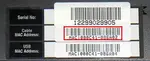
Troubleshooting
The modem lights indicate the current status of your cable modem. To troubleshoot any connection problems, use the table below.
| Modem Light | Status | Problem |
|---|---|---|
| Power | Solid Green | None. |
| Off | No power. Verify power supply connections and electrical outlet. Also make sure the outlet is not connected to a switch. | |
| Cable | Slow Flashing green |
Searching for cable connection. Verify all cable connections and try resetting the modem. |
| Fast Flash Modem | Searching for cable connection. If this is a new modem or a replacement modem, you must contact Cox with your MAC address Click Here. If there are several MAC addresses on the modem, please use the “HFC” or “RF” MAC address. | |
| Off | No connection cable connection. Verify all cable connections and try resetting the modem. | |
| Activity | Flashing Green | Traffic is passing through the cable modem port. |
| Ethernet | Solid Green | None. Ethernet connection to computer found. |
| Off | No Ethernet found. Verify Ethernet cable connections, the TCP/IP settings and the NIC. You might need to reinstall the NIC drivers. | |
| USB | Solid Green | None. USB connection to computer found. |
| Off | No USB found. Verify USB cable connections, the TCP/IP settings and the USB cable. You might need to reinstall the USB drivers. |
Modem InformationDOCSIS 3.0 Cable Modem 16×4 channel bonding To achieve Gigablast or Ultimate Classic speeds, a DOCSIS 3.1 modem is required |
Highest Service LevelPreferred 150 |
Front View
|
After the cable modem is successfully registered on the network, the Power, Receive, Send, and Status indicators illuminate continuously to indicate that the cable modem is online and fully operational. | |
Back View
|
The Linksys CM3016 has the following ports available on the back of the modem.
|
|
MAC Address
|
MAC addresses are written as 12 digits containing both letters and numbers (0-9, A-F). A MAC address is unique. The first six characters of the MAC address are unique to the manufacturer of the device. |

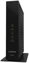
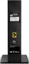
Troubleshooting
The modem lights indicate the current status of your cable modem. To troubleshoot any connection problems, use the table below.
| Modem Light | Status | Problem |
|---|---|---|
| Power | On | None – the modem is powered on |
| Off | No power – Verify power supply connections and electrical outlet. Ensure the outlet is not connected to a switch. | |
| Receive | Solid Blue | None – multiple downstream channels are in use |
| Solid Green | None – one downstream channel is in use | |
| Blinking | None – scanning for downstream channels | |
| Off | No downstream channels are in use – Verify all cable connections and try resetting the modem. | |
| Send | Solid Blue | None – multiple upstream channels are in use |
| Solid Green | None – one downstream channel is in use | |
| Blinking Green | None – scanning for an upstream channel | |
| Off | No upstream channels are in use – Verify all cable connections and try resetting the modem. | |
| Status | On | None – the modem is online |
| Blinking | None – the modem is registering a connection | |
| Off | The modem is offline – Verify all cable connections and try resetting the modem. | |
| Ethernet | On | None – a device is connected to the Ethernet port |
| Blinking | None – data is being transferred over the Ethernet connection | |
| Off | No device is connected or the device is disabled – Verify all cable connections and try resetting the modem. |
User Guide
RE6300/RE6400
Introduction
This User Guide can help you connect the extender to your network and solve common setup issues. You can find more help from our award-winning, 24/7 customer support at Linksys.com/support.
Overview

RE6300 Front

RE6400 Front
The light on the front of the range extender gives you information about power, updating and signal strength.

Side

Power Switch European versions only.
Wi-Fi Protected Setup Button and LED Use Wi-Fi Protected Setup to automatically and securely add compatible wireless devices to your network. Refer to Using Wi-Fi Protected Setup on page 7.
Reset Press and hold for about five seconds to reset to factory defaults. You can also restore the defaults from Administration> Factory Default Screen in the extender’s Browser-based utility. Reset Instructions
Bottom

Ethernet (blue) Connect wired devices to your wireless network with Ethernet (network) cables. The green light turns on when an Ethernet device is connected and active on this port. The light blinks when the extender is sending or receiving data over the Ethernet port.
How to install the range extender
Before setup, unplug or disconnect any range extenders on the network.
1. Plug in the range extender midway between your router and the area without Wi-Fi.
Be sure you have the least 50% of your Router’s Wi-Fi signal at that point on the device you will use for setup. The setup software will help you find the best spot if you have trouble.
2. Wait for a solid light on the cover of the range extender. It could take up to two minutes. On a computer, phone or tablet, connect to the Wi-Fi networks ” Linksys Extender Setup”
3.If setup Does not start automatically, Open a Browser to http://extender.linksys.com.
Linksys’s spot finder technology will help you find the right location for your range extender if you have trouble. You will be guided to place the range extender closer orfarther from your router to improve the signal. If you nailed it with your first placement you will not see Spot finder screens.
4. During setup you will be asked whether you want the range extender to update itself automatically. If you allow automatic updates, the range extender will download and install updates when released by Linksys. Automatic updates will take place overnight so they do not disrupt your network activity.
You also can decide to manually update your range extender at your convenience.

Post set-up LED behavior mention here as well and in the QSG
TIP
You can also connect the range extender by using Wi-Fi Protected Setup. For more
information see ” Using Wi-Fi Protected Set” on page 7
Special Feature – Music Streaming
Wireless Music Playback
Stream music through your AC1200 MAX range extender to connected speakers.
iOS devices:
? Connect iOS device to the same Wi-Fi network as your range extender.
? Swipe up from the bottom of your screen.
? Tap on Linksys Range Extender.

Android devices
For Samsung Galaxy
? Connect Galaxy device to the same Wi-Fi network as your range extender.
? Select Music app
? Choose music file and tap Screen Mirroring icon ![]()
? Choose Linksys Range Extender.

Your screen might look different depending on your device model and version of Android.
For other Android devices, stream music with MediaHouse, UPnPlay, Skifita, ArkMC,
BubbleUPnP, Pixel Media, and 2Player 2.0.
Windows
? Open Windows Media Player
? Right-click on music file and choose Linksys Range Extender.

This list of supported media players is subject to change with the release of new
software or mobile apps.
? Windows users can stream music with Windows Media Player12.
? Mac users can stream music with proprietary software or the SofaPlay app..
? Android users can stream music with MediaHouse, UPnPlay, Skifita, ArkMC, BubbleUPnP, Pixel Media, and 2Player 2.0.
? IOS devices including iPhone, iPad or iPod can stream music with proprietary software or other apps such as, , ArkMC, Smartstor Fusion, , Mconnect, and DK UPnP/DLNA.
? The extender supports MP3, FLAC, WAV, WMA and AAC file formats, as long as those formats are supported by the device and app doing the streaming.
? The 3.5mm stereo port supports earphones and powered speakers.
How to access the browser-based utility
After setting up the Extender Use the Exterder Browser-based utility to change any settings.
On a computer or device that is connected to your range extender, open any browser (Internet Explorer, Chrome, Firefox, Safari, etc.), and enter extender. linksys.com in the address bar.
You will be prompted to enter a user name and password. If you did not change them during setup, leave the user name blank and enter “admin” in the password fields. If you customized the SSID and password, enter those credentials.
If you are connected to your local network, but not to the range extender, you will need to enter the extender’s IP Address in your browse to access the extenders settings.
Windows XP:
1. Enable UPnP:
a) Click Start, Control Panel, Add or Remove Program, then click Add/Remove Windows Components.
b) Select Network Services, then click Details.
c) Select UPnP User Interface, then click OK.
2. Open Windows Explorer. Click My Network Places on the left panel.
3. Look for the RE6700 icon on the right panel. (You might be required to change the firewall for instructions.)
Windows 8, Windows 7, or Vista:
1. Open Windows Explorer (File Explorer in Windows 8). Click Network. Look for the RE6700 icon on the right panel. (You might be required to change the firewall settings to allow the display of network computers. Refer to your operating system help for instructions.
2. Right-click the RE6700 icon. Click Properties. Click on the address link in Device web page.
Mac OS X:
1. Open Safari. Be sure that Bonjour is included in the Bookmarks menu and Favorites bar.a. Go to Safari Preferences > Advanced and be sure each Bonjour box is selected.
2. Find Bonjour in the Bookmarks menu or Favorite bar and chose Linksys Extender If you have changed your network name and password, choose the network
name and enter the password you created.
Using range extender settings
Click Help on the right side of the screen for additional information on the screen options. Changes to settings will not be effective until you click Save at the bottom of the screen. You also can click Cancel to clear any changes.

Using Wi-Fi Protected Setup
Wi-Fi Protected Setup makes it easy to connect your Extender to your network and connect other devices to your network through the extender.
Wi-Fi Protected Setup light activity


Connecting the extender to an existing access point
If your access point or router supports it, you can use Wi-Fi Protected Setup to connect the range extender to the access point or router. Log in to the browser-based utility and click on WPS in the left navigation bar. Choose from the setup methods below to connect the extender.
NOTE
If you have an access point or a router that does not support Wi-Fi Protected Setup, note the wireless settings, and then manually configure the extender.
Connecting with the Wi-Fi Protected Setup Button
Use this method if your router or access point has a Wi-Fi Protected Setup button

1. Press the Wi-Fi Protected Setup button on the extender. If you have a dual-band router you will do this again to extend the second network. The 2.4 GHz band will be extended first.
2. Click the Wi-Fi Protected Setup Burton on Router Wi-Fi Protected Setup screen (if available), OR press and hold the Wi-Fi Protected Setup button on the router for one second. When the connection is complete, the Wi-Fi Protected Setup light on the extender will be solid.
3. If you use the Extender’s Wi-Fi Protected Setup screen, click OK in that screen within two minutes.
TIP
You can also access WPS in the browser-based utility by clicking WPS in the left navigation bar.
Connecting with the Range Extender PIN
The Wi-Fi Protected Setup PIN (Personal Identification Number) can be found on the product label on the back of the Extender, You can Use the Method, if only your Router administration utility has a Wi-Fi Protected Setup menu.
1.Enter the Exterder Pin into the Appropriate Field on the Router’s Wi-Fi Protected Setup screen. Click Register. When the connection is complete, the Wi-Fi Protected Setup light on the extender will be solid.
2. Click OK.
Connecting devices to your network through the extender
Choose from the methods below to connect devices that support Wi-Fi Protected Setup to your network. Delete the screen below
NOTE
Repeat the instructions for each client device that supports Wi-Fi Protected Setup.
Connecting with the Wi-Fi Protected Setup Button
Use this method if your client device has a Wi-Fi Protected Setup button.
1. Press the Wi-Fi Protected Setup button on the client device.
2. Click the Wi-Fi Protected Setup button on the Extender’s Wi-Fi Protected Setup screen, OR press and hold the Wi-Fi Protected Setup button on the side of the extender for one second. When the connection is complete, the Wi-Fi Protected Setup light on the extender will be solid.
3. If Using the Extender Wi-Fi Protected Setup screen, be sure to click OK within two minutes or you will have to start over.
Connecting With the Client Device PIN
Use this method if your client device has a Wi-Fi Protected Setup PIN (Personal Identification Number).

1.Inter the PIN from Device in the fielt on Extender Wi -Fi Protected Setup screen.
2. Click Register on the Extender Wi-Fi Protected Setup screen. When the connection is complete, the Wi-Fi Protected Setup light on the extender will be solid.
3. Click OK on the Extender Wi-Fi Protected Setup screen within two minutes or you will have to start over.
Connecting with the Extender PIN
Use this Method if your Client device ask for the Extender PIN.
1. On the Client Device enter the PIN, Listed on the Extender Wi-Fi Protected Setup screen. (It is also listed on the product label on the back of the extender.) When the connection is complete, the Wi-Fi Protected Setup light on the extender will be solid.
2. Click OK on the Extender Wi-Fi Protected Setup screen within two minutes.
How to use Site Survey
Site Survey gives a snapshot of all neighboring access points and wireless routers within range of the extender.
To open the Site Survey page:
1. Log in to the browser- Based Utility see( How to access on the Browser on page 5).
2. Click the Wireless tab. Click the Site Survey page.
3. Select?To connect to a wireless network, click the button next to the wireless network name (SSID) in the Select column, and click Connect.
4. SSID?Displays the name of neighboring wireless networks.
5. GHz?Displays the radio band (in GHz) of the neighboring wireless networks
6. Signal Strength?Displays the relative position of the neighboring access points by indicating the power of the wireless signal received: dot only = 25%, dot + one
wave = 50%, dot + two waves = 75%, dot + three waves = 100%. If no waves are displayed, your extender is too far from the upstream access point or the signal is blocked. Try to keep the signal strength between 60% and 100% for optimum performance.
7. Security?Displays the mode of security in use by the neighboring APs. If a network supports Wi-Fi Protected Setup, the Wi-Fi Protected Setup icon is also displayed.

To connect your extender with an access point or router in Site Survey, you will need to know the password or passphrase of the network on that device.
1. Select the network name (SSID) that you want to repeat with your extender by clicking the corresponding button in the Select column.
2. Click Connect. When prompted, enter the password or passphrase used to secure your wireless network. The type of security information required in this screen must Much your Access.
TIP: For dual-band networks, be sure to connect to both bands, 2.4 GHz and 5 GHz.

3. Click Save. Your extender wireless parameters should be configured. The wireless interface will restart, and the extender will connect to the access point or router you have chosen.
Cross-Band
Cross-Band is the simultaneous use of both bands for high-speed data transfer and uninterrupted streaming and gaming.
Troubleshooting
NOTE Your RE6700 works on 2.4GHz and 5 GHz networks.
You cannot get your extender connected
Check the position of your router and extender
? For first-time setup, you may need to place the extender closer to the router. after you have setup your extender you can unplug it and move it from the final location.
? To reduce signal obstructions, try alternate locations for the router and extender.
? Avoid placing the router and extender near metal objects, masonry walls, and reflective surfaces such as glass or mirrors.
? Avoid placing the router and extender near other electronics that may cause signal interference.
If you are using Wi-Fi Protected Setup to connect, wait until the Wi-Fi Protected
Setup indicator stops blinking before trying to make the connection again.
You cannot access your range extender To access your range extender, you must be connected to your own network. If you currently have wireless Internet access, the problem may be that you have accidentally connected to a different wireless network.
For Mac Instruction Please see the MAC Section.
To fix the problem on Windows computers:
1. On your Windows desktop, right-click the wireless icon in the system tray. The icon might look different depending on which version of Windows you are running.
2. Click View Available Wireless Networks.

3. Select your network name. Click Connect. In the example below, the computer was connected to another wireless network named JimsRouter. The name of the correct network, BronzeEagle in this example, is selected.

4. If you are prompted to enter a network key, type your password (Security Key) into the Network key and Confirm network key fields. Click Connect.You should now be able to access the Range Extender Browser-based utility.
To fix the problem on Mac computers:
1. In the menu bar across the top of the screen, click the Wi-Fi icon. Linksys Connect has automatically assigned your network a name. In the example below, the computer was connected to another wireless network named JimsRouter. The name of the Linksys E-Series network, BronzeEagle in this example, is selected.

2. Select the wireless network name of the router you want to connect to.
3. Type your wireless network password (Security Key) into the Password field. Click OK.

You should be able to access now the range Extender Browser-based utility.
You have intermittent connection problems
Plug in the range extender midway between your router and the area without Wi-Fi. Be sure you have at least 50% of your Router Wi-Fi signal at that point on the device you used for setup.
Specifications
RE6300/RE6400
Model Name Linksys RE6300/RE6400
Model Description Dual-band Wireless-AC Range Extender
Model Number RE6300/RE6400
Standards IEEE 802.11ac, 802.11a, 802.11n, 802.11g,
802.11b, 802.3u
Ports Gigabit Ethernet, audio
Buttons Reset, Wi-Fi
(European model only)
LEDs Power/Wi-Fi Protected Setup, Ethernet (link,
activity)
Antennas 2 external (non-detachable)
Wireless Security Wi-Fi
Security Key Bits Up to 128-bit encryption
Environmental
Dimensions 2.64????1.49????4.13????67 x 38 x 105 mm)
Weight 5.12 oz (145 g)
Power 12VDC/1.0A
Certification FCC, ICES-003, RSS210, CE, Wi-Fi
Operating Temperature 32 to 104°F (0 to 40°C)
Storage Temperature -4 to 140°F (-20 to 60°C)
Operating Humidity 10 to 80% noncondensing
Storage Humidity 5 to 90% noncondensing
Specifications are subject to change without notice.
Visit linksys.com/support for award-winning 24/7 technical support
BELKIN, LINKSYS and many product names and logos are trademarks of the Belkin group of companies. Third-party trademarks mentioned are the property of their respective owners. Licenses and notices for third party software used in this product may be viewed here: http://support.linksys.com/en-us/license. Please contact
http://support.linksys.com/en-us/gplcodecenter for questions or GPL source code requests.
© 2015 Belkin International, Inc. and/or its affiliates. All rights reserved.
Federal Communication Commission Interference Statement
This device complies with Part 15 of the FCC Rules. Operation is subject to the following two conditions: (1) This device may not cause harmful interference, and (2) this device must accept any interference received, including interference that may cause undesired operation.
This equipment has been tested and found to comply with the limits for a Class B digital device, pursuant to Part 15 of the FCC Rules. These limits are designed to provide reasonable protection against harmful interference in a residential installation. This equipment generates, uses and can radiate radio frequency energy and, if not installed and used in accordance with the instructions, may cause harmful interference to radio communications. However, there is no guarantee that interference will not occur in a particular installation. If this equipment does cause harmful interference to radio or television reception, which can be determined by turning the equipment off and on, the user is encouraged to try to correct the interference by one of the following measures:
– Reorient or relocate the receiving antenna.
– Increase the separation between the equipment and receiver.
– Connect the equipment into an outlet on a circuit different from that to which the receiver is connected.
– Consult the dealer or an experienced radio/TV technician for help.
FCC Caution: Any changes or modifications not expressly approved by the party responsible for compliance could void the user’s authority to operate this equipment. This transmitter must not be co-located or operating in conjunction with any other antenna or transmitter. Operations in the 5.15-5.25GHz band are restricted to indoor usage only.
Radiation Exposure Statement:
This equipment complies with FCC radiation exposure limits set forth for an uncontrolled environment. This equipment should be installed and operated with minimum distance 22cm between the radiator & your body.
Note: The country code selection is for non-US model only and is not available to all US model. Per FCC regulation, all WiFi product marketed in US must fixed to US operation channels only.
Industry Canada statement:
This device complies with RSS-210 of the Industry Canada Rules. Operation is subject to the following two conditions: (1) This device may not cause harmful interference, and (2) this device must accept any interference received, including interference that may cause undesired operation.
Caution :
(i) the device for operation in the band 5150-5250 MHz is only for indoor use to reduce the potential for harmful interference to co-channel mobile satellite systems;
(ii) high-power radars are allocated as primary users (i.e. priority users) of the bands 5250-5350 MHz and 5650- 5850 MHz and that these radars could cause interference and/or damage to LE-LAN devices.
Advertisement:
Radiation Exposure Statement:
This equipment complies with IC radiation exposure limits set forth for an uncontrolled environment. This
equipment should be installed and operated with minimum distance 27cm between the radiator & your body.
Questions about your Linksys RE6300/RE6400? Post in the comments!
Download Linksys RE6300/RE6400 Manual [PDF]