![]()
ITEM #1438122
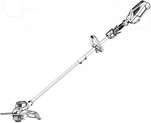
40 V LITHIUM-ION BRUSHED
MODEL #KST 2540-06
ATTACH YOUR RECEIPT HERE
Serial Number___________ Purchase Date____________
 Questions, problems, missing parts? Before returning to your retailer, call our customer service department at 1-888-3KOBALT (1-888-356-2258), 8 a.m. – 8 p.m., EST, Monday – Friday.
PH19151
1
PRODUCT SPECIFICATIONS
| SPECIFICATIONS | |
| Type | Cordless, battery-powered |
| Speed | 5500 RPM ± 10% /
5000 RPM ± 10% |
| Cutting path | 13 / 15 in. (330 / 381 mm) |
| Line diameter | 0.080 in. (2.0 mm) |
| Cutting capacity | Dual line |
| Weight without battery | 7.7 lbs. (3.5 kg) |
2
PACKAGE CONTENTS
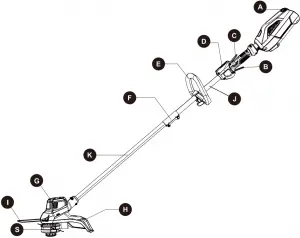
| PART | DESCRIPTION | QUANTITY |
| A | Battery Release Button | 1 |
| B | Trigger | 1 |
| C | Lock-off Lever | 1 |
| D | Speed Switch | 1 |
| E | Front/Auxiliary Handle | 1 |
| F | Coupler | 1 |
| G | Motor Housing | 1 |
| H | Guard | 1 |
| I | Edge Guide | 1 |
| J | Upper Tube | 1 |
| K | Lower Tube | 1 |
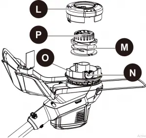
| L | Spool Cover (preassembled to Spool Housing) | 1 |
| PART | DESCRIPTION | QUANTITY |
| M | Spool (preassembled to Spool Housing) | 1 |
| N | Eyelet (preassembled to Spool Housing) | 1 |
| O | Spool Housing (preassembled to Lower Tube) | 1 |
| P | Bump knob | 1 |
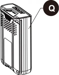
| Q | Battery | 1 |
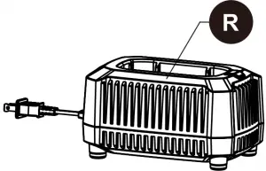
| R | Charger | 1 |
| S | String Head | 1 |
3
HARDWARE CONTENTS (not shown actual size)
AA
Screw (preassembled to the Guard (H)) Qty. 2
BB CC


Fastening Knob Qty. 1 Bolt Qty. 1
DD EE


Hex Wrench Qty. 1 Bracket Qty. 1
4
 SYMBOLS
Some of the following symbols may be used on this product. Please study them and learn their meaning. Proper interpretation of these symbols will allow you to operate the product better and safer.
| SYMBOLS | DESIGNATION | EXPLANATION |
| V | Volts | Voltage |
| A | Amperes | Current |
| Hz | Hertz | Frequency (cycles per second) |
| W | Watts | Power |
| no | No Load Speed | Rotational speed, at no load |
| ~ | Alternating Current | Type of current |
| /min | Per Minute | Revolutions, strokes, surface speed, orbits, etc., per minute |
 |
Direct Current | Type or a characteristic of current |
 |
Safety Alert | Indicates a potential personal injury hazard. |
 |
Read The Operator’s Manual | To reduce the risk of injury, user must read and understand operator’s manual before using this product. |
 |
Eye Protection | Always wear eye protection with side shields marked to comply with ANSI Z87.1. |
 |
Wet Conditions Alert | Do not expose to rain or use in damp locations. |
 |
No Blade | Do not install or use any type of blade on a product displaying this symbol. |
 |
Ricochet | Thrown objects can ricochet and result in personal injury or property damage. |
 |
Keep Bystanders Away | Keep all bystanders at least 50 ft. away. |
5
SAVE THESE INSTRUCTIONS
The following signal words and meanings are intended to explain the levels of risk associated with this product.
| SYMBOL | SIGNAL | MEANING |
|
DANGER | Indicates an imminently hazardous situation, which, if not avoided, will result in death or serious injury. |
|
WARNING | Indicates a potentially hazardous situation, which, if not avoided, could result in death or serious injury. |
|
CAUTION | Indicates a potentially hazardous situation, which, if not avoided, may result in minor or moderate injury. |
| CAUTION | (Without Safety Alert Symbol) Indicates a situation that may result in property damage. |
SERVICE
Servicing requires extreme care and knowledge and should be performed only by a qualified service technician. For service, return the product to your nearest AUTHORIZED SERVICE CENTER for repair. When servicing, use only identical replacement parts.
WARNING
- To avoid serious personal injury, do not attempt to use this product until you have read this Owner’s Manual thoroughly and understand it completely. If you do not understand the warnings and instructions in this Owner’s Manual, do not use this product. Call 1-888-3KOBALT (1-888-356-2258) for assistance.
- The operation of any power tool can result in foreign objects being thrown into your eyes, which can result in severe eye damage. Before operating a power tool, always wear safety goggles, safety glasses with side shields, or a full face shield when needed. We recommend a Wide Vision Safety Mask for use over eyeglasses or standard safety glasses with side shields. Always use eye protection that is marked to comply with ANSI Z87.1.
6
WARNING
Read and understand all instructions. Failure to follow all instructions listed below may result in electric shock, fire, and/or serious personal injury.
- Do not operate power tools in explosive atmospheres, such as in the presence of flammable liquids, gases, or dust. Power tools create sparks that may ignite the dust or fumes.
- Do not allow children or untrained individuals to use this unit.
- Don’t expose power tools to rain or wet conditions. Water entering a power tool will increase the risk of electric shock.
- Do not handle battery or tool with wet hands.
- Never allow children to operate the equipment. Never allow adults to operate the equipment without proper instruction.
- Always wear safety glasses with side shields that are marked to comply with ANSI Z87.1. Everyday glasses have only impact resistant lenses. They are NOT safety glasses. Following this rule will reduce the risk of eye injury. Use face mask if operation is dusty.
- Don’t use in the rain. Store indoors.
- Do not operate in poor lighting.
- Keep all parts of your body away from any moving part.
- Prevent unintentional starting. Ensure the switch is in the off-position before connecting to battery pack, picking up or carrying the appliance. Carrying the appliance with your finger on the switch or energizing appliance that have the switch on invites accidents.
- Do not force tool. Use the correct tool for your application. The correct tool will do the job better and safer at the rate for which it is designed.
- Do not operate the equipment while bare foot or when wearing sandals or similar lightweight footwear. Wear protective footwear that will protect your feet and improve your footing on slippery surfaces.
- Keep firm footing and balance. Do not overreach. Overreaching can result in loss of balance.
- Check Damaged Parts – Before further use of the appliance, a guard or other part that is damaged should be carefully checked to determine that it will operate properly and perform its intended function. Check for alignment of moving parts, binding of moving parts, breakage of parts, mounting and any other condition that may affect its operation. A guard or other part that is damaged should, be properly repaired or replaced by an authorized service center unless indicated elsewhere in this manual.
- Keep guards in place and in working order.
- Keep hands and feet away from cutting area.
- Do not allow to be used as a toy. Close attention is necessary when used by or near children.
- Do not use tool if switch does not turn it on or off. Any tool that cannot be controlled with the switch is dangerous and must be repaired.
- Keep all bystanders, children, and pets at least 50 ft. away.
- Do not operate this unit when you are tired, ill, or under the influence of alcohol, drugs, or medication.
7
- Do not put any object into openings. Do not use with any opening blocked; keep openings free.
- Check the work area before each use. Remove all objects such as rocks, broken glass, nails, wire, or string which can be thrown or become entangled in the machine.
- Use only identical manufacturer’s replacement parts and accessories. Use of any other parts may create a hazard or cause product damage.
- Do not charge battery in the rain, or damp or wet locations. Following this rule will reduce the risk of electric shock.
- For household use only.
- Battery tools do not have to be plugged into an electrical outlet; therefore, they are always in operating condition. Be aware of possible hazards when not using your battery tool or when changing accessories. Following this rule will reduce the risk of electric shock, fire, or serious personal injury.
- Remove or disconnect battery before servicing, cleaning or removing material from the gardening appliance.
- Use only Kobalt 40-volt batteries. (KB 240-06, KB 440-06, KB 245-06, KB 540-06, KB 640-06).
- Use only Kobalt 40-volt charger. (KRC 40-06, KRC 60-06).
- Use appliance only with specially designated battery packs. Use of any other battery packs may create a risk of injury and fire.
- Store idle appliances – When not in use, the string trimmer should be stored indoors in a dry, locked place out of the reach of children.
- Do not dispose of batteries in a fire. The cell may explode. Check with local codes for possible special disposal instructions.
- Do not open or mutilate the batteries. Released electrolyte is corrosive and may cause damages to the eyes or skin. It may be toxic if swallowed.
- Do not place battery tools or their batteries near fire or heat. This will reduce the risk of explosion and possibly injury.
- Batteries can explode in the presence of a source of ignition, such as pilot light. To reduce the risk of serious personal injury, never use any cordless product in the presence of an open flame. An exploded battery can propel debris and chemicals. If exposed, flush with water immediately.
- Do not crush, drop or damage battery. Do not use a battery or charger that has been dropped or received a sharp blow. A damaged battery is subject to explosion. Properly dispose of a dropped or damaged battery immediately.
- Exercise care in handling batteries in order not to short the battery with conducting materials such as rings, bracelets, and keys. The battery or conductor may overheat and cause burns.
- Under extreme usage or temperature conditions, battery leakage may occur. If liquid comes in contact with your skin, wash immediately with soap and water, then neutralize with lemon juice or vinegar. If liquid gets into your eyes, flush them with clean water for at least 10 minutes, then seek immediate medical attention. Following this rule will reduce the risk of serious personal injury.
- If the charger power supply cord is damaged, it must be replaced only by the manufacturer or by an authorized service center to avoid risk.
- Do not point the string trimmer in the direction of people or pets.
- When not in use, the string trimmer should be stored indoors in a dry, locked up place out of the reach of children.
- Maintain tool with care. Keep all vents and openings clean and clear of debris. Follow instructions for proper maintenance. Do not attempt to clear clogs from tool without first switching it off and removing the battery.
- Dress Properly – Do not wear loose clothing or jewellery. They can be caught in moving parts. Use of rubber gloves and substantial footwear is recommended when working outdoors. Wear protective hair covering to contain long hair.
- Use the Correct Appliance – Do not use appliance for any job except that for which it is intended.
- When battery pack is not in use, keep it away from other metal objects like paper clips, coins, keys, nails, screws or other small metal objects that can make a connection from one terminal to another.
Shorting the battery terminals together may cause burns or a fire. - Do not expose a battery pack or appliance to fire or excessive temperature. Exposure to fire or temperature above 265°F may cause explosion.
- Follow all charging instructions and do not charge the battery pack or appliance outside of the temperature range specified in the instructions. Charging improperly or at temperatures outside of the specified range may damage the battery and increase the risk of fire.
- Have servicing performed by a qualified repair person using only identical replacement parts. This will ensure that the safety of the product is maintained.
- Do not modify or attempt to repair the appliance or the battery pack (as applicable) except as indicated in the instructions for use and care.
- Ambient temperature range:
– String trimmer storage temperature range: -4°F (-20°C) – 158°F (70°C)
– String trimmer operation temperature range: -4°F (-20°C) – 104°F (40°C)
– Battery charging temperature range: 39°F (4°C) – 104°F (40°C)
– Charger operation temperature range: 39°F (4°C) – 113°F (45°C)
– Battery discharging temperature range: 6.8°F (-14°C) – 113°F (45°C)
Child safety
Tragic accidents can occur if the operator is not aware of the presence of children.
- Keep children out of the working area and under the watchful care of a responsible adult.
- Do not allow children under the age of 14 to operate this trimmer. Children who are 14 years of age or older must read and understand the operating instructions and safety rules in this manual and must be trained and supervised by a parent.
- Stay alert and turn the trimmer off if a child or any other person enters the working area.
- Look behind and down for small children before and while cutting backwards.
- Use extreme care when approaching blind corners, doorways, shrubs, trees, or other objects that may obscure your view of a child who may run into the path of the trimmer.
SAVE THESE INSTRUCTIONS
9
PREPARATION
Before beginning assembly of product, make sure all parts are present. Compare parts with package contents list and hardware contents list. If any part is missing or damaged, do not attempt to assemble the product.
Estimated Assembly Time: 5 – 10 minutes
ASSEMBLY INSTRUCTIONS
WARNING
To avoid injury and to reduce the risk of electical shock or fire:
- Replace the battery or charger immediately if the battery case or charger cord is damaged.
- Always make sure the string trimmer switch is OFF before inserting or removing the battery.
- Always make sure the battery is removed and the switch turned OFF before inspecting, adjusting, or maintaining any other part of the string trimmer.
- Read, understand, and follow the Battery Charger instructions.
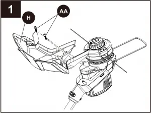
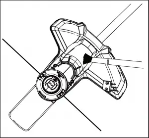
1. Guard
To avoid injury, always remove the battery before installing the guard, changing a cutting line, or making any adjustments.
If the guard is damaged, do not use the grass trimmer/edger until it is replaced.
Note: Install the protective guard before operating the grass trimmer/edger. It should not be removed or disassembled.
a. Remove the battery.
b. Invert the grass trimmer/edger to access the trimmer head.
c. Using the hex wrench (DD), remove the pre-installed screws (AA) from the trimmer head.
d. Place the guard (H) onto the trimmer head.
e. Align the screw holes on the guard with the screw holes on the trimmer head.
f. Insert the screws into the trimmer head and tighten to fasten the guard in place.
Hardware Used
AA Screw x 2
DD Hex wrench x 1
10
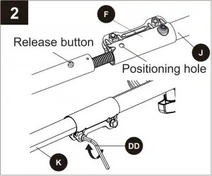
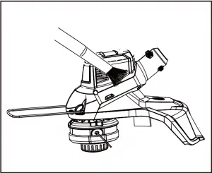
2. Connect upper/lower trimmer tubes
a. Push in the release button located on the lower tube (K). Align the release button with the positioning hole on the upper tube (J) and slide the two tubes together. Rotate the lower tube until the release button locks into the positioning hole.
b. Tighten the screw with the hex wrench (DD).
Hardware Used
DD Hex wrench x 1
WARNING
To avoid injury, adjust the auxiliary handle for optimum control and balance. Do not overreach when operating grass trimmer/edger. Keep proper balance at all times for better control of the tool in unexpected situations.
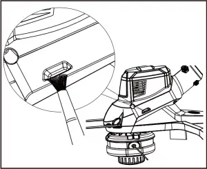
3. Front handle
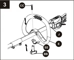
a. Position the front/auxiliary handle (E) onto the upper portion of the trimmer section by sliding over the upper tube (J).
b. Once the front handle is in the desired position, align the hole on the handle with the hole on the bracket (EE), then slide the bolt (CC) through the top of the handle and secure with the fastening knob (BB).
Tighten until there is no movement in the handle.
c. The front handle can be adjusted to a suitable position.
Note: Do not overtighten the fastening knob. It could cause the fastening clamp to break.
Hardware Used
BB Fastening knob x 1
CC Bolt  x 1
x 1
EE Bracket x 1
11
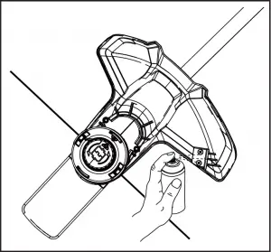
Cutting line
A spool of cutting line is pre-installed on the trimmer.
When the cutting line needs replacing, rewind new line onto existing spool.
CAUTION: To avoid injury, always remove the battery before installing the guard, changing a cutting line, or making any adjustments.
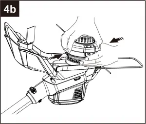
4. To remove the cutting line:
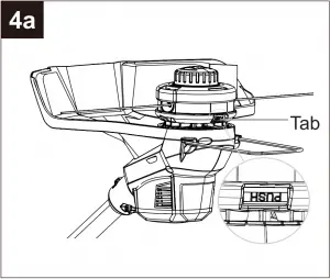
a. Remove the battery from the trimmer.
b. Turn the string trimmer over to access the spool.
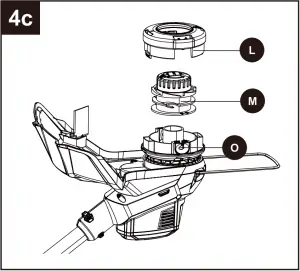
c. Remove the spool cover (L) by pressing on the two tabs parallel to each other on the sides of the spool cover (L).
d. Remove the spool (M) from the spool housing (O) and remove any excess line.
e. Reinstall the spool and spool housing.
12
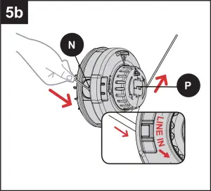
5. To Install the cutting line
Note: For 0.080 in. (2.0 mm) nylon line, do not put more than 13 feet of cutting line in at a time.
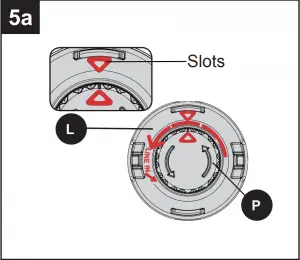
a. Remove battery before installing new line.
b. Line up the slots on the bump knob (P) with the slots on the spool cover (L).
c. Insert line through the eyelet (N). Push line until it exits the opposite string head hole.
d. Pull the line through until there is an equal amount of line on each side.
e. Turn the bump knob (P) counterclockwise to begin winding the string into the string head (S). Leave approximately 5 inches of string protruding out of each side of the head.

13
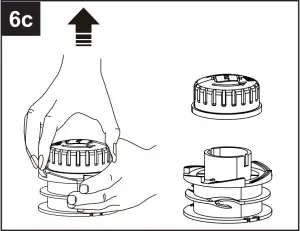
6. To replace the bump knob
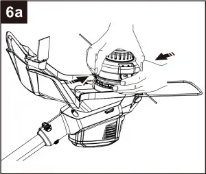
a. Remove the battery pack.
b. Turn the string trimmer over to access the spool.
c. Remove the spool cover (L) by pressing on the two tabs parallel to each other on the sides of the spool cover (L).
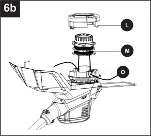
d. Remove the spool (M) from the spool housing (O).
e. While holding the bump knob, firmly pull it out.
f. Replace with a new bump knob.
Reinstall the spool and spool housing.
14
7. Battery
IMPORTANT: The battery is not charged when it is purchased. Before using the trimmer for the first time, place the battery in the battery charger and charge.
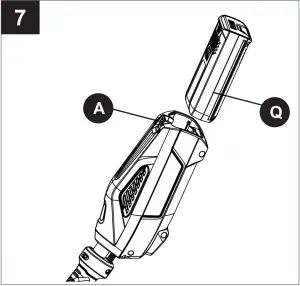
7. To install:
a. Align the battery (Q) with the cavity in the string trimmer housing.
b. Insert the battery into the handle until the battery release button (A) locks into place. Push down on the battery until it locks into place. You should hear a “click” once it is installed.
Note: The battery can only be installed one way.
7b. To remove:
a. Press the battery release button (A) on the string trimmer. This will cause the battery to raise out of the tool slightly.
b. Grasp the trimmer firmly and pull the battery out of the handle.
Note: The battery fits into the handle snugly in order to prevent accidental dislodging.
WARNING: Follow these instructions in order to avoid injury and to reduce the risk of electric shock or fire:
- Replace the battery immediately if the battery case is damaged.
- Verify that the switch is in the OFF position before inserting or removing the battery.
- Verify that the battery is removed and the switch is in the OFF position before inspecting, adjusting, or performing maintenance on any part of the string trimmer.
8. Adjusting the cutter blade
This trimmer is equipped with a line cut-off blade on the guard. Advance line whenever you hear the engine running faster than normal or when trimming efficiency diminishes. This will maintain best performance and keep line long enough to advance properly.
This trimmer is currently set at the 13 in. cutting swath.
To adjust to a cutting swath of 15 in.:

a. Remove the battery from the string trimmer.
b. Remove both screws on the cut-off blade with a Phillips head screwdriver.
c. Rotate the cut-off blade 180°.
d. Replace both screws in the cut-off blade.
Note: Set the cut-off blade to 13 in. for greater runtime.
Set the cut-off blade to 15 in. for greater cutting area.
15
OPERATING INSTRUCTIONS
WARNING
To avoid injury:
- Do not squeeze the trigger while the grass trimmer/edger is inverted.
- Do not carry the grass trimmer/edger with your finger on the switch. Avoid unintentional starting.
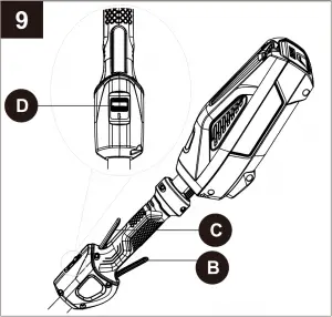
1. To turn on/off:
a. Slide the speed switch (D) to the desired operating speed. Slide the speed switch to position 1 for low speed or position 2 for high speed.
b. Press the lock-off lever (C). Squeeze the trigger (B) to start.
c. Release the trigger (B) to stop.
CAUTION: Always allow 5 seconds or more for the cutting line spool to stop rotating after releasing the trigger. Do not invert the grass trimmer/ edger or place your hands under the protective guard until the grass trimmer/edger spool has come to a complete stop.
2. Lengthening the line
While the string trimmer is operating, the cutting line gets worn down and becomes shorter. This trimmer is equipped with bump feed line advancement, which advances additional line once the head is bumped on the ground while rotating. The cut-off blade will cut the line to keep an accurate cutting swath.

16
Trimmer tips
Before each use:
- Make sure the protective guard is tightly installed. If not, tighten the guard screws.
- Before trimming, inspect the area for string, wire, branches or other material that may become entangled in the cutting line and thrown.
Storage tips:
- Do not store the grass trimmer/edger in sunlight, in an excessively warm place, or near a furnace. The battery life will be shortened.
During use:
- Trim only when the grass and weeds are dry.
- Do not trim grass at night. Always make sure you have adequate lighting.
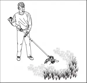
- Hold the grass trimmer/edger by both the switch handle and the auxiliary handle for best control and balance.
- Stand with the cutting head tipped down at an angle in front, guiding the grass trimmer/edger in a semicircular motion around you.
- If possible, guide the grass trimmer/edger to the left to cut. The line will cut as soon as it leaves the guard, and the clippings are thrown away from you.
- To produce a smoothly trimmed area, move the grass trimmer/edger out of the area being cut with consistent speed and height.
- Use only the tip of the cutting line to do the trimming, especially near walls and fences. Trimming with the side of the cutting line may overload the motor, wear out the line faster, and break the line more often.
- Do not rest the trimmer spool on the ground while trimming. This will cause spool wear and battery drain.
- If the grass is higher than 6 in. (15 cm), trim in small stages.
- When the grass trimmer/edger is turned off and the spool stops rotating, the cutting line will relax and may recede. Feed extra cutting line before storing the trimmer to prevent losing the line completely into the spool.
- If the diameter of the cutting area gets smaller, the line is worn down and needs to be advanced more often.
- If the grass trimmer/edger is not cutting correctly, the cutting line may not be feeding properly.
- Remove and rewind the line spool.
17
CARE AND MAINTENANCE
Trimmer Guard and Motor Maintenance
Note: Before performing maintenance, remove battery from the tool.
1. Remove dirt and debris from guard using a paint brush (not included).
2. Clean dirt and debris off of motor cover and connection joints.
3. Clean the grass in the air vents after trimming.
4. Clean line cutter blades by using a wire brush and spraying with an appropriate degreaser.
18
4. Inspect bump knob and line to ensure that there is an adequate amount of line and that no damage is present on the bump knob.
TROUBLESHOOTING
If you still have questions or an unresolved issue after going through this troubleshooting guide, or just want to speak to a Kobalt product expert, please call our customer service department at 1-888-3KOBALT (1-888-356-2258), 8 a.m. – 8 p.m., EST, Monday – Friday.
| PROBLEM | POSSIBLE CAUSE | CORRECTIVE ACTION |
| Motor fails to start when switch trigger is depressed. | 1. Battery is not secure. 2. Battery is not charged. 3. Possible wiring or electrical contact problem. |
1. To secure the battery, make sure the latches on the battery compartment snap into place. 2. Charge the battery according to the instructions included with your model. 3. Call 1-888-3KOBALT (1-888-356-2258) for technical service. |
| Trimmer smokes during operation. | 1. Trimmer damaged. | 1. Do not use the string trimmer. |
| Trimmer head will not advance line. | 1. The motor shaft or trimmer head is bound with grass. 2. Not enough line in the spool. 3. Trimmer head is dirty. 4. Line is tangled on the spool. |
1. Stop the trimmer, remove the battery, and remove any grass. 2. Remove the battery and replace the trimmer line. Reference section “Cutting Line” in this manual. 3. Remove the battery and clean the spool. 4. Remove the battery, remove the line from the spool and rewind. |
| Line is not cutting well. | 1. The cutting blade on the guard has become dull. | 1. Sharpen the cutting blade with a file or replace it with a new blade. |
19
WARRANTY
5-YEAR LIMITED WARRANTY
This Kobalt 40 V String Trimmer is warranted to the original purchaser from the original purchase date for five (5) years subject to the warranty coverage described herein.
This Kobalt 40 V String Trimmer is warranted for the original user to be free from defects in material and workmanship.
If you believe that the kobalt 40V String Trimmer is defective at any time during the specified warranty period, simply return the 40 V String Trimmer along with proof of purchase to the place of purchase for a free replacement or refund, or call 1-888-3KOBALT (1-888-356-2258) for warranty service.
This warranty is void if: defects in materials or workmanship or damages result from repairs or alterations which have been made or attempted by others or the unauthorized use of nonconforming parts; the damage is due to normal wear, damage is due to abuse (including overloading of the tool beyond capacity), improper maintenance, neglect or accident; or the damage is due to the use of the tool after partial failure or use with improper accessories or unauthorized repair or alteration.
This warranty excludes spool.
This warranty gives you specific legal rights, and you may also have other rights that vary from state to state.
20
REPLACEMENT PARTS LIST
For replacement parts, call our customer service department at 1-888-3KOBALT (1-888-356-2258), 8 a.m. – 8 p.m., EST, Monday – Friday.
BB CC DD E H
EE S

| PART | DESCRIPTION | PART # |
| BB | Fastening knob | 341201444 |
| CC | Bolt | 322051444 |
| DD | Hex wrench | 329011444 |
| E | Front/auxiliary handle | 341191444A |
| EE | Bracket | 33304877B |
| H | Guard | C1101005-00 |
| S | String head | C1101008-00 |
Printed in China
21
]]>
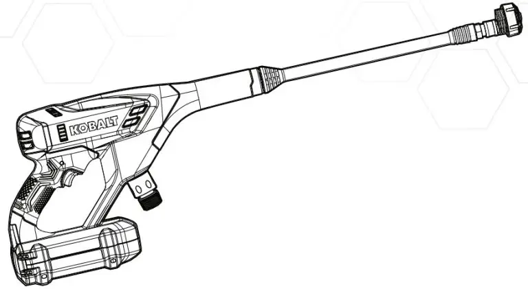
ITEM #2735850/ 2737923
RENAELC REWOP DLEHDNAH SSELDROC V04
MODEL #KPC 2040-06/ KPC 7040-06
KOBALT and K & Design are trademarks
or registered trademarks of LF, LLC. All rights reserved.
ATTACH YOUR RECEIPT HERE
Serial Number……..
Purchase Date………
 Questions, problems, missing parts? Before returning to your retailer, call our customer service department at 1-888-3KOBALT (1-888-356-2258), 8 a.m. – 8 p.m., EST, Monday – Sunday. You could also contact us at [email protected] or visit www.lowespartsplus.com.
SM20336
PRODUCT SPECIFICATIONS
| SPECIFICATIONS | |
| Voltage | 40 V |
| Max. Pounds Per Square Inch Pressure | 600 PSI |
| Max. Gallons Per Minute | 0.8 GPM |
| Maximum Inlet Water Temperature | 104°F (40°C) |
| Cleaning Units | 360 C.U. |
| Net Weight | 2.76 kg (6.08 lb) |
THE RECOMMENDED AMBIENT TEMPERATURE RANGE
| Power Cleaner storage temperature range | 32 ˚F (0 ˚C) ~ 113 ˚F (45 ˚C) |
| Power Cleaner operation temperature range | 32 ˚F (0 ˚C) ~ 113 ˚F (45 ˚C) |
| Battery charging temperature range | 39 ˚F (4 °C) ~ 104 ˚F (40 ˚C) |
| Charger operation temperature range | 39 ˚F (4 °C) ~ 104 ˚F (40 ˚C) |
| Battery discharging temperature range | 32 °F (0 °C) ~ 113 ˚F (45 ˚C) |
| Battery storage temperature range | 32 °F (0 °C) ~ 113 °F (45 °C) |
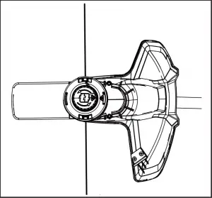
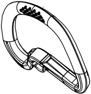
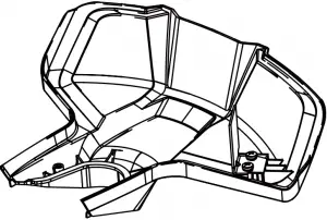
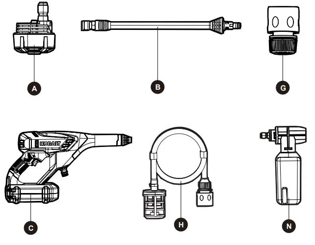
PACKAGE CONTENTS

| PART | DESCRIPTION | QUANTITY |
| A | 5 in 1 Spray nozzle | 1 |
| B | Spray wand | 1 |
| C | Front handle | 1 |
| D | Water inlet | 1 |
| E | Battery compartment | 1 |
| F | Trigger | 1 |
SAFETY INFORMATION
General Use
 WARNING
- Read all the instructions before using the product.
- To reduce the risk of injury, close supervision is necessary when a product is used near children.
- Know how to stop the product and bleed pressure quickly. Be thoroughly familiar with the controls.
- Stay alert – Watch what you are doing.
- Do not operate the product when fatigued or under the influence of alcohol or drugs.
- Keep operating area clear of all persons.
- Do not overreach or stand on unstable support. Keep good footing and balance at all times.
- Follow the maintenance instructions specified in the manual.
- Risk of Injection or Injury– DO NOT DIRECT DISCHARGE STREAM AT PERSONS.
- Read all safety warnings and instructions. Failure to follow the warnings and instructions may result in electric shock, fire, and/or serious injury.
- Prevent unintentional starting. Ensure the switch is in the off-position before connecting to the battery pack, picking up or carrying the appliance. Carrying the appliance with your finger on the switch or energizing an appliance that has the switch on invites accidents.
- Disconnect the battery pack from the appliance before making any adjustments, changing accessories, or storing the appliance. Such preventive safety measures reduce the risk of starting the appliance accidentally.
- For use only with KB 240C-06 battery.
- For use only with KRC 40-06 charger.
- When the battery pack is not in use, keep it away from other metal objects, like paper clips, coins, keys, nails, screws or other small metal objects, that can make a connection from one terminal to another. Shorting the battery terminals together may cause burns or a fire.
- Do not use a battery pack or appliance that is damaged or modified. Damaged or modified batteries may exhibit unpredictable behavior resulting in fire, explosion or risk of injury.
- Do not expose a battery pack or appliance to fire or excessive temperature. Exposure to fire or temperature above 265°F may cause an explosion.
- Follow all charging instructions and do not charge the battery pack or appliance outside of the temperature range specified in the instructions. Charging improperly or at temperatures outside of the specified range may damage the battery and increase the risk of fire.
- Have servicing performed by a qualified repair person using only identical replacement parts . This will ensure that the safety of the product is maintained.
- Do not modify or attempt to repair the appliance or the battery pack (as applicable) except as indicated in the instructions for use and care.
WARNING PROPOSITION 65
Some dust is created by power sanding, sawing, grinding, drilling, and other construction activities that contain chemicals known to cause cancer, birth defects, or other reproductive harm. Some examples of these chemicals are:
- Lead from lead-based paints
- Crystalline silica from bricks and cement and other masonry products
- Arsenic and chromium from chemically treated lumber
Your risk from these exposures varies, depending on how often you do this type of work.
To reduce your exposure to these chemicals: work in a well-ventilated area, and work with approved safety equipment, such as those dust masks that are specially designed to filter out microscopic particles.
PREPARATION
Before beginning the installation of the product, make sure all parts are present. Compare parts with package contents list and hardware contents list. If any part is missing or damaged, do not attempt to assemble, install or operate the product.
Estimated Assembly Time: 1-2 minutes.
ASSEMBLY INSTRUCTIONS
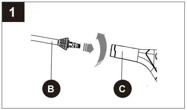
1. INSTALL THE SPRAY WAND
- Push the end of the spray wand (B) into the gun handle (C).
- Turn the spray wand (B) clockwise until the tabs lock into position.

2. INSTALL THE SPRAY NOZZLE
- Pull back the quick-connect collar on the spray wand (B).
- Insert the spray tip (A) onto the spray wand (B).
- Release the quick-connect collar to attach the spray tip (A).
- Pull-on spray tip (A) to ensure it is properly installed and does not pull out.
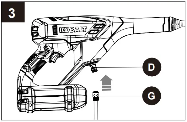
3. INSTALL THE SELF-SIPHON HOSE
- Insert one end of the self-siphon hose (G) into the water intake (D).

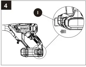
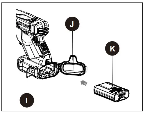
4. INSTALL THE BATTERY PACK
- Pull back on the hinge lock lever (I).
- Unhook the hinge (I) from the battery door (J).
- Open the battery door (J).
- Align the lift ribs on the battery pack (K) with the grooves in the battery compartment.
- Push the battery pack (K) into the battery compartment until the battery pack (K) locks into place.
- When you hear a click, the battery pack is installed.
- Close the battery door (J) and lock the hinge (I).
5. REMOVE THE BATTERY PACK
- Pull back on the hinge lock lever (I).
- Unhook the hinge (I) from the battery door (J).
- Open the battery door (J).
- Push and hold the battery release button (L).
- Remove the battery pack (K) from the machine.
OPERATING INSTRUCTIONS
1. USE THE SPRAY GUN
WARNING
For safe control, keep your hands on the gun at all times.
- Keep pressing the lock-out button (M), pull and hold the spray gun trigger (F) to start the machine.
- Release the lock-out button (M) and spray gun trigger (F) to stop water flow through the spray tip.

2. ADJUST THE SPRAY NOZZLE
WARNING
Before you adjust the spray nozzle:
- Pull the spray gun trigger to release water pressure.
- Stop the machine.
WARNING
Do not point the spray wand at your face or others’.
1. Rotate the spray nozzle to adjust the spray setting (A).
NOZZLE TYPE
| SPRAY SETTING | APPLICATION |
 |
The 0-degree tip provides a straight line of spray. It provides the highest amount of pressure. It is best used for removing hard, stuck-on grime or dirt. |
 |
The tip provides high versatility with its 15-degree angle tip. Referred to as the washing tip, because it provides adequate pressure to remove dirt from surfaces, but is designed to not damage many surfaces. This pressure washer tip is designed for “sweeping” foliage or debris given its wide-angle. This tip is versatile due to its wide area of cleaning and strong pressure application. |
 |
The tip provides high versatility with its 25-degree angle tip. Referred to as the washing tip, because it provides adequate pressure to remove dirt from surfaces, but is designed to not damage many surfaces. This pressure washer tip is designed for “sweeping” foliage or debris given its wide-angle. This tip is versatile due to its wide area of cleaning and strong pressure application. |
 |
The 40-degree tip, referred to as the “fan” tip creates the widest area of cleaning with relatively low pressure. This pressure washer tip is best used for light or delicate cleaning applications. It is recommended for light cleaning on wood decks and other soft or delicate surfaces. |
 |
The shower spray tip is used for shower application. The shower is applied under low-pressure high volume for optimum performance. The shower cannot be applied under high pressure with this machine. |
APPLICATIONS
You may use this product for the purposes listed below:
- Cleaning boats, cars, trucks, motorcycles, outdoor furniture, grills, house siding, driveways, patios, and decks.
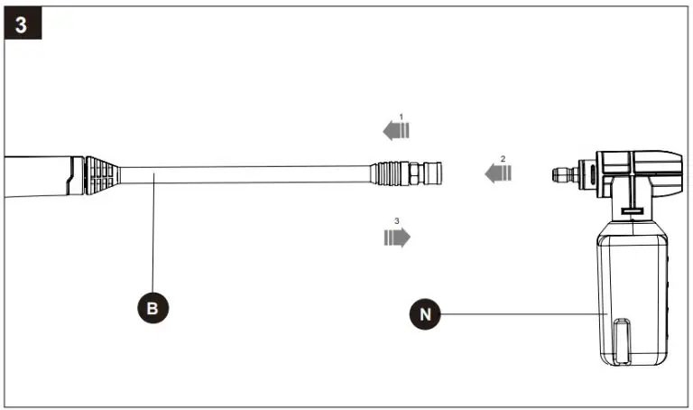
3. DETERGENT ADDING AND USE
Use only detergents designed for pressure washers; household detergents, acids, alkaline, bleaches, solvents, flammable material, or industrial grade solution can damage spray nozzle. Many detergents may require mixing prior to use. Prepare cleaning solution as instructed on the solution bottle.
SOAP APPLICATION
Soap is applied under low-pressure high volume for optimum performance.
TO ADD DETERGENT:
- Pour detergent in the detergent tank (N).
- Install the soap tank (N) to the spray wand (B).
- Start the pressure washer and spray the detergent on a dry surface using long, even, overlapping To prevent streaking, do not allow detergent to dry on the surface.

CAUTION
Use only approved pressure washer cleaners. Do not use bleach, chlorine, or any cleaners containing acids.
NOTE: Use a funnel, if needed, to prevent accidental spilling of the detergent outside the tank. If any detergent is spilled during the filling process, make sure the unit is cleaned and dried before proceeding.
CARE AND MAINTENANCE
To promote longer life of the power cleaner:
- Do not run over the hose with vehicles or drag over sharp surfaces, as this could damage the hose and cause leaks.
- Run clean, freshwater through the kit, then turn off the pressure washer and water supply.
- Depressurize by squeezing the gun trigger until all the water has been drained out of the Unit.
- The unit can now be disconnected safely for storage in a cool dark area, or to remove debris from individual parts.
WARNING
Keep hose away from hot surfaces (like a muffler). If the hose develops a leak, do not try to repair it.
REPLACE THE ENTIRE HOSE. The hose is for cold water pressure washers only. DO NOT use hot water or steam service.
TROUBLESHOOTING
| PROBLEM | POSSIBLE CAUSE | CORRECTIVE ACTION |
| Gun and/or hose leaks. | 1. Loose connection. 2. 0-ring is missing or damaged. |
1. Tighten the connections. 2. Turn off and depressurize the unit. Disconnect, remove and replace old o-ring. |
| Unit won’t spray. | 1. Power or water supply is not on. 2. hose, gun, wand, or nozzle is clogged. |
1. Turn power or water supply on. 2. Consult the troubleshooting list below for these specific parts and instructions. |
| Wand/Nozzle | Wand/nozzle is clogged or the spraying pattern is uneven. | Turn off and depressurize unit. Remove wand/nozzle from gun outlet. Look through the opening in wand; you should see light through the nozzle end. If not, then reverse flush with air or water to dislodge debris. |
| Gun | Gun is clogged. | Turn off and depressurize unit. Remove wand from gun and gun from hose. Reverse flush the gun with air or water to dislodge debris. |
| Hose | Hose is clogged. | Turn off and depressurize unit. Remove gun from hose and hose from unit. Flush the hose with air or water to dislodge debris. |
| The machine does not start. | The battery is not charged. | Charge the battery by following the procedures in the battery and charger manual. |
| The battery is too cold. | Remove the battery from the unit. Place the battery on the charger and allow it to charge for 10 minutes or until the charging light turns green. Remove from the charger and install in a unit for use. |
WARRANTY
5-YEAR REPAIR WARRANTY
This Kobalt 600 PSI power cleaner is warranted to the original purchaser from the original purchase date for five (5) years subject to the warranty coverage described herein.
This Kobalt 600 PSI power cleaner is warranted for the original user to be free from defects in material and workmanship.
If you believe that Kobalt 600 PSI power cleaner is defective at any time during the specified warranty period, simply call our warranty service (1-888-356-2258) along with proof of purchase.
This warranty is void if: defects in materials or workmanship or damages resulting from repairs or alterations which have been made or attempted by others or the unauthorized use of nonconforming parts; the damage is due to normal wear, the damage is due to abuse (including overloading of the tool beyond capacity), improper maintenance, neglect or accident; or the damage is due to the use of the tool after partial failure or use with improper accessories or unauthorized repair or alteration.
This warranty gives you specific legal rights, and you may also have other rights that vary from state to state.
REPLACEMENT PARTS LIST
For replacement parts, call our customer service department at 1-888-356-2258, 8 a.m. – 8 p.m., EST, Monday – Sunday. You could also contact us at [email protected] or visit www.lowespartsplus.com.

| PART | DESCRIPTION | PART # |
| A | Spray tip | C1104655-00 |
| B | Gun Wand | C4102326-00 |
| C | Trigger handle | C1105936-00 |
| G | Connector | C1100521-00 |
| H | Self-siphon hose | C1104825-00 |
| N | Detergent tank | C1104657-00 |
KO-7504GF Voltage and GFCI Outlet Tester
Instruction Manual
ITEM#0909981
VOLTAGE & GFCI OUTLET TESTER
MODEL#KO-7504GFI|
KOBALT and logo designs are trademarks or registered trademarks of LF, LLC. All rights reserved.
ATTACH YOUR RECEIPT HERE
Serial Number………………………
Purchase Date……………………….
Please read and understand this entire manual before attempting to assemble, operate or install the product. · Double Insulation: The tester is protected
throughout by double insulation or reinforced insulation.
![]() WARNING
WARNING
- Use extreme caution when checking electrical circuits to avoid injury due to electric shock.
- The manufacturer assumes basic knowledge of electricity on the part of the user and is not responsible for any injury or damages due to improper use of this tester.
- This product does not sense DC voltage or potentially hazardous voltages below 50 volts.
- To assure the unit is operating, always test on a known live circuit before use.
- This tester will not detect voltages in wires that are electrically shielded by metal conduit or grounded electrical enclosures.
CAUTION
- OBSERVE AND FOLLOW all standard industry safety rules and electrical codes. When necessary call a qualified electrician to troubleshoot and repair the defective electrical circuit.
![]() Questions, problems, missing parts? Before returning to your retailer, call our customer service department at 1-888-3KOBALT (1-888-356-2258), 8 a.m – 8 p.m., EST, Monday – Sunday. You could also contact us at [email protected] or visit www.lowespartsplus.com.
Questions, problems, missing parts? Before returning to your retailer, call our customer service department at 1-888-3KOBALT (1-888-356-2258), 8 a.m – 8 p.m., EST, Monday – Sunday. You could also contact us at [email protected] or visit www.lowespartsplus.com.
PRODUCT SPECIFICATIONS
| Operating Range | 115 – 125 VAC, 50-60 Hz |
| Operating Range (NCV Detection) | 50 – 600 VAC, 50-60 Hz |
| Certifications and Compliance | Conforms to UL 1436 (Circuit Tester) UL 61010-1 & 61010-2-030 (NCV Detection), CE, CAT III 1000V |
| Indicators | Visual Only (circuit tester), Audible and visual (Non-contact voltage detection) |
| Battery | One LR44 |
| Operating Environment | 32° – 104° F (0 – 40° C) 80% RH max., 50% RH above 30° C, Altitude up to 2000 meters, Indoor use, Pollution degree 2, Accordance with IED-664. |
| Cleaning | Remove grease and grime with a clean, dry cloth. |
OPERATING INSTRUCTIONS
Outlet Circuit Tester Operation:
- Plug the tester into any 120 Volt standard or GFCI outlet.
- Only a single LED should illuminate
- The text adjacent to the lit LED will indicate the wiring condition.
- If no LED illuminates then the hot is open
- If the tester indicates a wiring problem then turn off all power to the outlet and repair wiring.
- Restore power to the outlet and repeat steps.
NOTICE:
- All appliances or equipment on the circuit being tested should be unplugged to help avoid erroneous readings.
- Not a comprehensive diagnostic instrument but a simple instrument to detect nearly all probable common improper wiring conditions.
- Refer all indicated problems to a qualified electrician
- Will not detect two hot wires in a circuit.
- Will not detect a combination of defects.
- Will not indicate a reversal of grounded and grounding conductors.
TO TEST GFCI PROTECTED OUTLETS:
- To test GFCI (Ground Fault Circuit Interrupter) protected circuits plug tester into GFCI protected outlet. Verify the power is on and that the outlet is wired properly.
- Press the GFCI test button.
- If the circuit is wired properly the main GFCI outlet should trip and power to the circuit will be cut off (this is indicated by the LED lights on the tester going off).
NOTICE:
- Consult the GFCI manufacturer’s installation instructions to determine that the GFCI is installed in accordance with the manufacturer’s specifications.
- Check for correct wiring of the receptacle and all remotely connected receptacles on the branch circuit
- Operate the test button on the GFCI installed in the circuit. The GFCI must trip. If it does not — do not use the circuit — consult an electrician. If the GFCI does trip, reset the GFCI. Then, insert the GFCI tester into the receptacle to be tested.
- Activate the test button on the GFCI tester for a minimum of 6 seconds when testing the GFCI condition. Visible indication on the GFCI tester must cease when tripped.
- If the tester fails to trip the GFCI, it suggests:
a.) a wiring problem with a totally operable GFCI or
b.) proper wiring with a faulty GFCI. Consult with an electrician to check the condition of the wiring and GFCI.
Non-Contact Voltage Detection Operation:
- Before use test the battery by pressing the yellow button at the NVC detection end. The LED will flash and the speaker will chirp momentarily if the battery is good. If the indicators do not function or the chirp continually cycles, then replace the battery.
- To test for voltage press and hold the yellow button at the NVC detection end. Place the probe tip on or near the wire, device or circuit to be tested. If AC voltage greater than 50 VAC is present the LED will flash and the speaker will chirp continuously.
NOTICE:
- Static Electricity The tester is subject to electrical static interference. If the LED or tone activates momentarily it is detecting static electricity. When detecting voltage the LED and tone will cycle continuously.
- NCV detection antennae interference The presence of objects near the probe tip can decrease the sensitivity of the tester. Keep your finger away from the LED lens and probe tip to ensure adequate detection range.
Caution: GFCIs are sometimes installed in 2- wire systems (no ground wire available). This may or may not meet the local code. This tester will not trip GFCI outlets installed without a ground wire. On two-wire systems use the test and reset buttons on the GFCI outlet to demonstrate proper operation. To detect which downstream outlets are protected by the GFCI place the tester in these outlets and use the test and reset buttons. Watch for the LEDs on the tester to turn off, this will indicate proper operation.
BATTERY INSTRUCTIONS
The product comes complete with one LR44 BATTERY in the package. To Install or Replace:
- Orient the tester backside up, locate the battery compartment marked with the battery symbol secured with a screw.
- Once the battery compartment is located, use a small Phillips head screwdriver to remove the screw & release the battery cover.
- Remove the LR44 battery using caution to prevent damage or injury to the internal components.
- Place battery into tester as shown on the battery cover (Positive terminal facing toward the NCV end of the product).
- Replace battery cover and screw.
- Test on known live circuits to verify tester functionality.
WARRANTY
1-Year Limited Warranty Questions, problems, missing parts?
Before returning to your retailer, call our customer service department at 1-888-3
KOBALT (1-888-356-2258), 8 a.m. – 8 p.m., EST, Monday – Sunday.
You could also contact us at [email protected]
visit www.lowespartsplus.com.