Holybro Kakute F7 V1.5 User Manual &
Overview
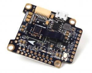
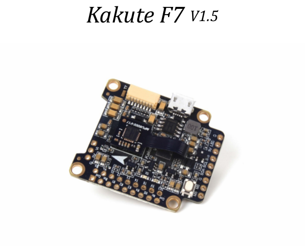
The Holybro Kakute F7 flight controller makes it easy to build your multirotor. It integrates flight controller (FC) and on-screen display (OSD) in one. The Kakute F7’s layout makes it easy to wire up the other components of the multirotor while keeping the build neat and tidy.
IMU upgraded to MPU6000,Re-designed and more reliable damping structure
Features
- Supports Betaflight, Butter flight, and Clean flight.
- Betaflight OSD. Change PIDs, adjust common configuration parameters, and change video transmitter channel and power level, all using your transmitter sticks and goggles.
- Soft-mounting built in. The IMU (“gyro”) chip on this board is mounted on vibration-isolating foam. This means that there is no need to soft-mount the board itself.
- High-performance / low-noise / high sensitivity IMU. MPU6000 with 6-axis gyro and accelerometer.
- Ready for autonomous flight: Integrated BMP280 barometer and SCL/SDA pads for use with external GPS/magnetometer units.
- Dedicated bootloader button for easy firmware flashing.
- Low-profile design fits into even very compact frames.
- Input voltage 7v to 42v. Power the board directly from the flight pack, up to 6S (on “B+” pad only).
- Automatic voltage monitoring. No need to run a separate vBat wire for voltage monitoring; the Kakute F7 monitors voltage directly from the power supply.
- Filtered voltage output for clean, noise-free video. On-board regulators output 5v at up to 2 amps and 3.3v at up to 200 mA to power peripherals such as receiver, video transmitter, FPV camera, or LED strip.
- Supports BLHeli pass-through for easy ESC upgrade and configuration.
Specifications
- MCU: STM32F745 32-bit processor
- IMU: MPU6000 (SPI)
- Barometer: BMP280
- Current Sensor: Approximately 130 amps maximum measurable value
- USB VCP Driver (all UARTs usable simultaneously; USB does not take up a UART)
- 6 hardware UARTS (UART1,2,3,4,6,7)
- All UARTS support hardware inversion. SBUS, Smart Port, and other inverted protocols work on any UART without “uninvent hack”.
- Supports serial receivers (SBUS, iBus, Spektrum, Crossfire) only. PPM and PWM receivers are not supported.
- TF card for Blackbox logging
- Dimensions: 35x41x7mm (includes foam-mounted gyro board in height)
- Mounting Holes: Standard 30.5mm square to center of holes
- Weight: 8g
Warranty and Return Policy
If you believe that your Kakute F7 is defective, please contact us. If we determine that the board is defective, it will be repaired or replaced at no charge to you. We may ask you to send your Kakute to our service center for examination or repair. Shipping costs are your responsibility. Returned items should include the original packaging and all accessories.
If product is damaged or defective, we will repair or replace it. Refunds are only given when product is lost by the shipping company. The refund amount is limited to the price of the product. Shipping costs are never refundable.
Contact us at:
- Email: [email protected]
- Facebook Page: Holybro
- Facebook Group: Holybro Hobby Official Group
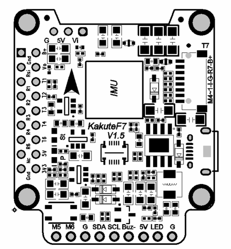
Pinout Diagram
| Pin | Function |
| B+ | Battery positive voltage (2S-6S) |
| 5v | 5v output (2A max) |
| VO | Video output to video transmitter |
| VI | Video input from FPV camera |
| G or GND | Ground |
| SDA, SCL | I2C connection (for peripherals) |
| R1, T1 | UART1 RX and TX |
| R2, T2 | UART2 RX and TX |
| R3, T3 | UART3 RX and TX |
| R4, T4 | UART4 RX and TX |
| R6, T6 | UART6 RX and TX |
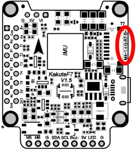
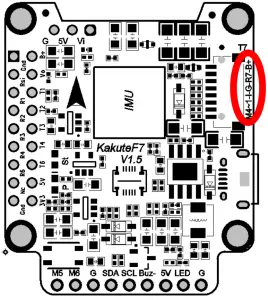
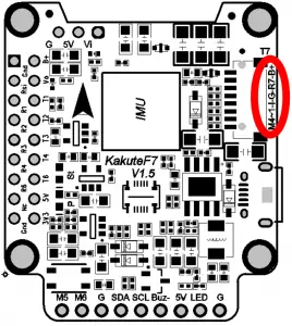
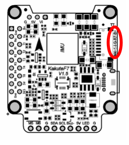
| R7, T7 | UART7 RX and TX (RX is located in the plug for use with 4-in-1 ESCs) |
| LED | WS2182 addressable LED signal wire |
| Buz- | Piezo buzzer negative leg |
| Connect buzzer positive leg to 5v pad | |
| 3V3 | 3.3v output (200 mA max) |
| M1 to M4 | Motor signal outputs (located in plug) |
| M5, M6 | Additional motor signal outputs (located at side of board) |
| RSI | Analog RSSI (0-3.3v) input from receiver |
| NC | NC |
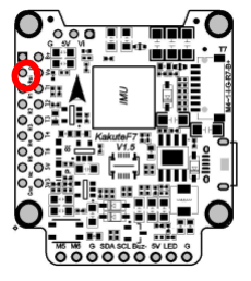
| Boot | Bootloader button |
Installation Guide
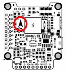
| Install the Kakute F7 in your quadcopter frame. Do not completely reassemble the frame. Leave the Kakute F7 accessible so that you can solder wires to it. For example, leave the top plate of your frame off so that you are working only with the base-plate.
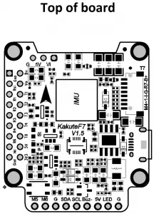
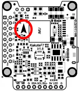
Having the Kakute F7 mounted in the frame will allow you to ensure that wire lengths are correct as you solder accessories to the board. When in doubt, it’s always better You will most likely be installing the Kakute F7 with a Power Distribution Board (PDB) or a 4-in-1 ESC. The Kakute F7 will probably install on top of this board, in the flight control stack. You should install the motors on the frame, solder the motor wires to the ESC, and solder the ESCs to the PDB (if you’re using a PDB) before you begin installing the Kakute F7. Be 100% sure that the front-facing arrow on the Kakute F7 faces the front of the quadcopter! If for some reason this is not possible, then you must use Cleanflight or Betaflight’s “board align” feature to compensate. |
 |
 “Board Align” Feature Documentation
https://www.youtube.com/watch?v=QeuSq71pYF0
| You must use a receiver that supports a serial protocol such as SBUS, iBus, Spektrum, or Crossfire. You cannot use a PPM or PWM receiver with the Kakute F7.
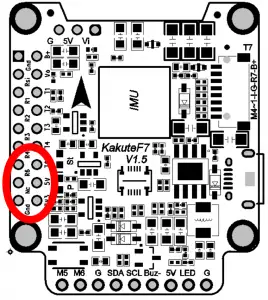
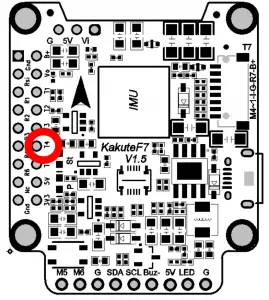
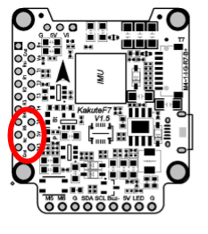
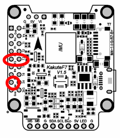
For all receiver types except Crossfire, solder the receiver signal wire to pad R6. If you are using a typical cable, the signal wire will be white or yellow. For Crossfire, connect pin 1 on the receiver to pad R6; connect pin 2 on the receiver to pad T6. (You will need to set up the Crossfire receiver to output CRSF protocol on pins 1 and 2. This is outside the scope of this manual.) Solder the receiver ground wire to the GND pad below R6. In a typical cable, the ground wire will be black or brown. If your receiver requires 5v power (most receivers except for Spektrum Satellite), solder its power wire to the 5v pad that is beneath T6 and next to CAM. In a typical cable, the power wire will be red or orange. If your receiver requires 3.3v power (most Spektrum Satellite receivers), solder its power wire to the 3v3 pad in the lower- right corner of the pin header. Do not connect a receiver that takes 3.3v power to a 5v pad or you will destroy it. Be sure to reference the pinout diagram for your receiver, to ensure that you are connecting the correct pads together. |
 |
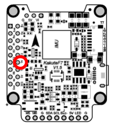
| Telemetry allows the Kakute F7 to report values, such as battery voltage, back to your transmitter. The transmitter can be configured to give audible alerts on low battery, and other such functions. Telemetry is also useful because it allows the use of “Lua Scripts” to configure the quadcopter from the transmitter.
If you intend to use telemetry, solder the telemetry wire from your receiver to the T4 pad on the Kakute F7. On FrSky receivers, the telemetry wire is labeled as SmartPort. If you are using Crossfire, there is no separate telemetry wire. |
 |
Before wiring up your camera and video transmitter (vTX), you must determine whether you will power them by 5v or battery voltage (vBat). You must refer to the product specifications for your camera and video transmitter to determine what maximum voltage they allow. These can typically be found on the product listing page of the vendor that sells the equipment.
If the voltage that you will use to power the copter (such as 4S or 5S) is too high for your camera or vTX, you must power them from the 5v regulator. If the voltage that you will use to power the copter is less than the maximum rated voltage of your camera and vTX, you may power them from vBat. Most cameras today can take up to 6S voltage safely. Many vTX can take up to 6S voltage, however the TBS Unify Pro is one exception: it requires 5v maximum.
Remember that the rated load of the 5v regulator on the Kakute F7 is 2 amps. This means that the sum of the accessories you run from the regulator cannot exceed 2 amps. This should be enough current to run a camera, receiver, and video transmitter (even a high-powered vTX like the Unify Pro). However, if you have other 5v accessories, such as 5v LEDs, you might exceed the rated capacity of the 5v regulator. In that case, you would have to run some of the accessories from vBat, to remove load from the regulator. When accessories are run directly from vBat, they do not load the regulator.
To recap: the sum of the current drawn by all accessories on the 5v pads must be less than 2 amps.
| Solder the video wire from the video transmitter (vTX) to the VO pad on the Kakute F7.
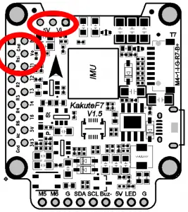
Solder the video wire from the camera to the VI pad on the Kakute F7. Depending on whether you intend to run off vBat or 5v, solder the power wire for the camera and vTX to either the 5v or the B+ pad nearest to where you soldered the video wire. Solder the ground wire from the camera and the vTX to the G pad nearest to where you soldered the video wire. |
 |
Some video transmitters allow the channel, transmit power, and other such parameters to be configured remotely, through the Betaflight OSD. This means you can change channel and transmit power using your goggles and transmitter sticks, instead of pushing a button or flipping DIP switches on the vTX itself. This is a huge convenience!
| If you have a vTX that supports vTX Remote Control, then:
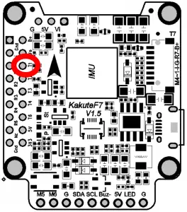
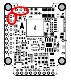
For SmartAudio vTX including TBS Unify, Holybro Atlatl V2, and RaceDayQuads Mach 2, solder the audio wire from the vTX to the T1 pad on the Kakute F7. For Tramp Telemetry vTX including the ImmersionRC Tramp and the Holybro Atlatl V1, solder the T wire from the vTX to the T1 pad on the Kakute F7. Other vTX may label this pin differently. Refer to their documentation. |
 |
| RSSI monitoring allows you to view the signal strength of the control link between your transmitter and your receiver in the OSD. This can give a warning when you are getting close to the edge of your range, as well as showing you if you have damaged equipment, such as an antenna that has been cut by a prop.
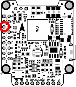
If you intend to use the RSSI input, solder the analog RSSI output of your receiver to the RSSI pad on the Kakute F7. Many receivers do not support analog RSSI output, so you may not be able to use this feature. |
 |
 How to wire up analog RSSI to your receiver
https://www.youtube.com/watch?v=pX_PWoLhooU
 An alternate way to get RSSI in your OSD
https://www.youtube.com/watch?v=t-evOAS9Mkg
| Some ESCs support a feature called ESC Telemetry. This feature allows the ESC to report data such as motor RPM and amps being used by the ESC back to the flight controller. Since the Kakute F7 does not have a built-in PDB, it cannot measure current directly, and it can take advantage of this feature.
If your ESCs support telemetry, and if you intend to use it, then solder each of the ESC telemetry wires to the R7 pad that is in the plug header. The Kakute F7 comes with a plug that fits into this header. |
 |
| Connect the ESC signal wires to the M1, M2, M3, and M4 wires coming out of the plug header. The Kakute F7 comes with a plug that fits into this header. The motor outputs are numbered M4 (closest to the USB port), then 3, 2, 1 (farthest from the USB port).
It’s important to connect these wires to the correct motor on your quadcopter. In Betaflight and Cleanflight, the motors are numbered: 1 – Back Right 2 – Front Right 3 – Back Left 4 – Front Left The signal wire is a thin wire, typically yellow or white. Since the Kakute F7 comes with a pre-wired plug, you will need to connect the wires from the Kakute to the wires from your ESCs. Alternatively, you might de-solder the signal wires from your ESCs and solder the Kakute wires directly to the ESCs. Some ESCs have a signal ground wire and some ESCs don’t. If your ESC has a thin black wire that is twisted with the signal wire, that is the signal ground. Since the Kakute does not have signal ground pads, we suggest cutting the ground wire off your ESCs or desoldering it. |
 |
| Connect the B+ wire in the plug header to a battery voltage source, such as the battery + pad on your PDB or 4-in-1 ESC. Your PDB or 4-in-1 ESC may have another vBat pad that is specifically designed for powering an accessory like the Kakute F7. It’s simpler to use a dedicated pad or wire, rather than soldering to the main battery + pad.
Connect the G wire in the plug header to a Ground source, such as the battery – pad on your PDB or 4-ni-1 ESC. |
 |
FPV Camera Control is a feature of Betaflight that allows you to access your FPV camera’s on-screen menu using your transmitter sticks. With this feature, you can easily adjust brightness, contrast, and other camera settings in response to changing lighting conditions.
There are two forms of Camera Control: analog and digital. Analog camera control is for cameras that use an analog-style joystick input. Digital camera control is currently reserved for some Runcam cameras. Look at the plug on the back of your camera. If you see a pin labeled “OSD” then your camera uses analog control. If you have a Runcam camera with pins labeled “RX” and “TX”, then your camera uses digital control.
Updating Betaflight Firmware
Like all software, the software that runs your flight controller has versions. Just like Windows XP was followed by 2k, then 7, 8, and 10. The software that runs your flight controller is called Betaflight.
Putting a new version of Betaflight on your Kakute F7 is called “flashing” your board.
Even if you decide you don’t want to update your firmware right now, you still need to install the VCP driver to configure the board. So, you must at least go through step 1 below to use your board.
Installing Drivers
Before you can flash your board, you must get the drivers installed on your computer. If you are on . You do not need to perform this step. You may skip directly to “Installing Betaflight Configurator”.
If you are on Windows, you must install the drivers manually. This is a place where beginners often struggle. We’re going to present the steps here, and if you can follow them, then great, but many people won’t be able to follow them. If you need a more personal approach, here is a link to a video that walks you through the process in more detail.
All About Betaflight Drivers, Including How to Install Them
https://www.youtube.com/watch?v=m4ygG6Y5zXI
Here are the steps you will perform:
- Download the Virtual COM Port (VCP) driver installer from here. Unfortunately, you must either create a login or give them your email address, then wait for them to email you a link, to download the actual installer. We recommend that you create a user login because the “send you a link in an email” method sometimes takes a long time to go through.
a. To create a login at the STM site, first go to this URL.
b. Click “Create an Account”
c. Enter your information in the next page and click “Register”
d. You will receive a confirmation email. Complete the confirmation process.
e. Log in to the STM site using the login you just created and download the VCP driver installer from the link in step 3. - Run the VCP installer and let it finish.
- Download the ImpulseRC Driver Fixer from here.
- Run the ImpulseRC Driver Fixer. It will instruct you to plug in your flight controller.
- Plug the Kakute F7 into your PC via USB. The ImpulseRC Driver Fixer should complete successfully.
The video linked above shows a process of using Zadig to replace the VCP driver. The ImpluseRC Driver Fixer is an easier way of doing the same thing. So, use the ImpulseRC Driver Fixer and don’t mess around with Zadig like the video shows.
Is It Over Yet?
THAT WAS SUPER ANNOYING WASN’T IT. Yes… we know.
The good news is, you do not need to repeat this process again. Sort of. You never need to install the drivers again on this computer, unless you reinstall the operating system for some reason. If you use another computer for the first time, you will need to install those drivers on it. Also, you may need to rerun the ImpulseRC Driver Fixer sometimes when you go to flash the board. If you try to flash the board and it fails, repeat steps 3 through 5 above
Installing Betaflight Configurator
Betaflight is managed using the Betaflight Configurator application, also known for short as the Betaflight GUI, or just, “The GUI”. (GUI is pronounced “gooey” in case you wondered. Only weirdos say, “Gee You Eye”.) Download the Betaflight Configurator application here:
https://github.com/betaflight/betaflight-configurator/releases
This is a standard application package for Windows, MacOS, or Linux. After you download it, install and run it the same as any other application.
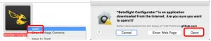
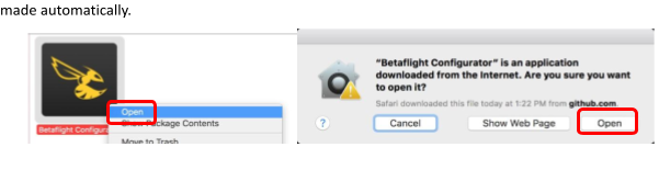
On MacOS you must give the application permission to run and access the network. The simplest way to do this is to right-click the installer and choose Open. A security prompt will appear asking, “Are you sure you want to open it?” Click Open on this prompt and the relevant configuration changes will be made automatically.
Flashing New Firmware
At this point, if you want to update your firmware, here is how to do it. But if you just want to go fly, please, go for it! You don’t have to be running the absolute latest firmware to have a good time. Just forget about this nonsense!
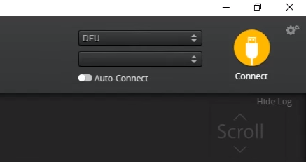
To flash your firmware, you must connect the board in “bootloader mode”. Bootloader mode means that the board is ready to accept new programming. To put the board into bootloader mode, hold down the bootloader button while plugging in the USB cable. Leave the button pressed for a moment after plugging in the USB cable to be sure it “takes”.
If your Kakute F7 is in bootloader mode, then you will see “DFU” in the pulldown menu in the upper right of the configurator, as shown here:
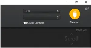
If you don’t see DFU in the pulldown menu, then either the board didn’t detect that you had the bootloader button pressed or your drivers are not installed correctly. If you don’t see DFU in the pulldown menu, you cannot flash new firmware to the board. It won’t work.
For the advanced users, a simpler way of getting into bootloader mode is to go to the CLI and type “b1”.
This will reboot the board into bootloader mode. This is especially useful if the board is installed in a copter where it isn’t convenient to press the bootloader button. In rare cases, the “b1” command doesn’t work and you must press the bootloader button on the board.

Here are the remaining steps:
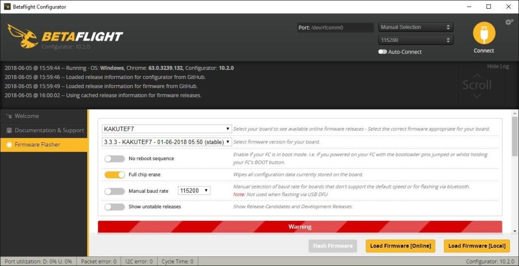
- Go to the “Firmware Flasher” tab.
- Select “KAKUTEF7V2” in the “Choose a board” pulldown menu. If you flash any other board type, the Kakute F7 will not function. It won’t be damaged, it just won’t work until you flash KAKUTEF7 to the board.
- Select the latest version of Betaflight in the “Choose a firmware version” pulldown menu.
- Click the “Load Firmware (Online)” button. The button will change to read “Downloading”. The Flash Firmware button will change from gray to orange.
- Click the “Flash Firmware” button. The screen should automatically scroll down to show the status bar, which will fill with orange as the flashing process completes.
- Flashing will be followed by a process called “Verifying”. Verification sometimes fails, but this isn’t a problem. If the flash completes, everything is usually fine.
- Un-plug your board and then plug it back in again, this time without holding down the bootloader button.
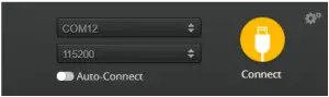
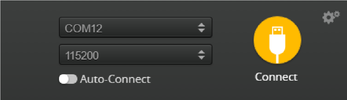
- For Windows users, the pulldown menu in the upper right of the configurator will read COM3 (or some other number). For MacOS and Linux users, the pulldown will read something starting with /dev/tty. This is normal. If the pulldown menu reads “Manual Selection” then your board is not being detected. This may indicate that you did not use the KAKUTEF7 target when you flashed the board. Or it may indicate that your Virtual COM Port (VCP) drivers were not installed correctly.
You are ready to configure your board.
Initial Configuration
The full configuration of Betaflight could take hours to document. In this section, we’ll describe a few things that are specific to this board. This won’t be enough to get you into the air, so we’ll also point you to some videos you can watch if you’re not perfectly sure what else you need to do. Even people have a few builds under their belt may be skipping some important steps without realizing it!
Connect to The Board
Plug the board in to USB. Start Betaflight Configurator. You should see “COM3” (or some other number) in the upper-right menu. Click “Connect”.
The GUI will load.
Ports
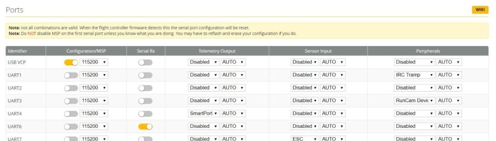
Click on the “Ports” tab on the left side of the window.
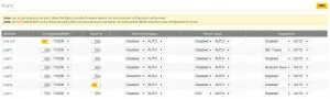
The UARTs on your Kakute F7 are versatile; any UART can be used for any function. This is different from the Kakute F4, in which certain functions had to be assigned to certain UARTs. In the wiring instructions above, certain UARTs were suggested, such as soldering the SBUS receiver to R6. However you don’t have to follow these recommendations if for some reason they don’t work for you. If you followed the instructions in this guide, the screen shot above shows how to configure the Ports tab.
When you configure the Ports, keep the following guideline in mind: each UART can be used for one function only. Each column (Serial RX, Telemetry Output, Sensor Input, Peripherals) represents a single function. So each UART row should only have one function active at a time. If you try to enable multiple functions, the configuration may be rejected, or the results may be unpredictable.
For each function, identify which UART number you connected the peripheral to. So if you soldered your receiver signal wire to pad R3, that would be UART3. If you soldered your SmartPort telemetry wire to pad T1, that would be UART1. The number following the R or T indicates the UART number.
On each row in the Ports tab, enable the one function that you connected ot the TX and/or RX pads for that UART. The most common options are below.
- USB VCP is the port that is used to talk between the Kakute F7 and the Configurator GUI. MSP is the protocol that they use to talk to each other. If you turn off MSP on USB VCP, you will not be able to contact the board any more via the Configurator. You will have to re-flash the board and erase your configuration to get back into it. Suffice it to say, this is bad, and you shouldn’t do it.
Don’t turn off MSP on the USB VCP line in the Ports tab. - If you are using FrSky SmartPort telemetry, in the Telemetry Output column, choose SmartPort from the pulldown menu.
- Enable “Serial RX” for the UART that you soldered the receiver signal wire to. If using an SBUS or Spektrum receiver, this will have been the RX pad only. For a Crossfire receiver, you will have used both the TX and RX pad of the same UART.
- If you are using RunCam digital camera control, in the Peripherals column, choose RunCam Device.
- If you are using ESC Telemetry, on the UART7 line, in the Sensor Input column, choose ESC.
Although you can technically use any RX pad for ESC Telemetry, the R7 pads are specifically located at the corners of the board for this purpose. - If you are using SmartAudio or ImmersionRC Tramp Telemetry to control your video transmitter: in the Peripherals column, choose either TBS SmartAudio or IRC Tramp, depending on which type of transmitter you are using.
Configuration
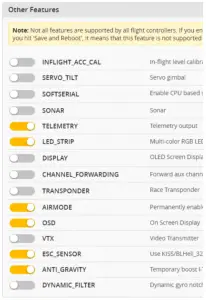
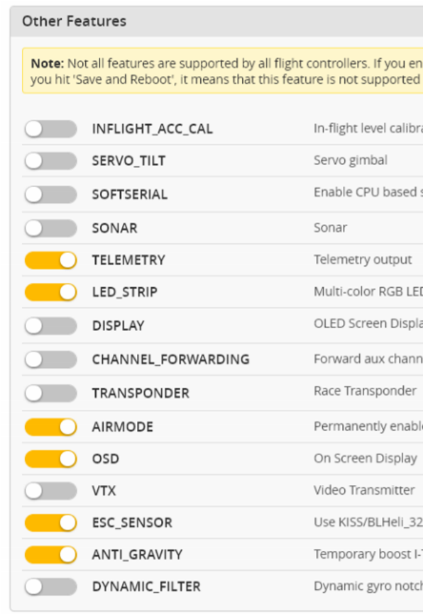
Click on the “Configuration” tab on the right side of the window. Scroll down to the “Other Features” section.
- If you are using any kind of telemetry (SmartPort, Crossfire, etc.), enable TELEMETRY.
- If you are using a programmable LED strip, enable LED_STRIP.
- Air Mode increases authority when the throttle is all the way down. We recommend leaving this option on all the time.
- The Kakute F7 has built-in Betaflight OSD. The OSD option should always be enabled.
- If you are using ESC telemetry, enable the ESC_SENSOR option.
- The ANTI_GRAVITY option increases the stability of the copter when the throttle is raised or lowered quickly. We recommend enabling this option, and setting Anti Gravity Gain to 3.0 in the PID Tuning tab. Detailed instructions for tuning this value are outside the scope of this manual, but this default setting will work well for most quads.
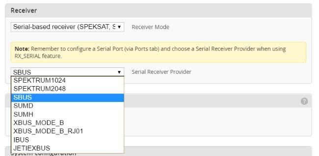
Next, go to the Receiver section of the “Configuration” tab. Since the Kakute F7 only supports serial-type receivers, configuration of this section is simple.
- Set the Receiver Mode to “Serial-based receiver”.
- Set the Serial Receiver Provider to the type that matches what kind of receiver you have. FrSky and other SBUS receiver should use SBUS. Spektrum Satellite receivers should use SPEKTRUM2048 or SPEKTRUM1024 depending on whether they are DSM2 or DSMX. FlySky receivers use iBus. Crossfire receivers use CRSF.
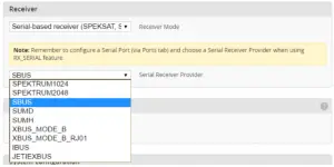
These are the most common serial receiver types that are likely to be encountered.
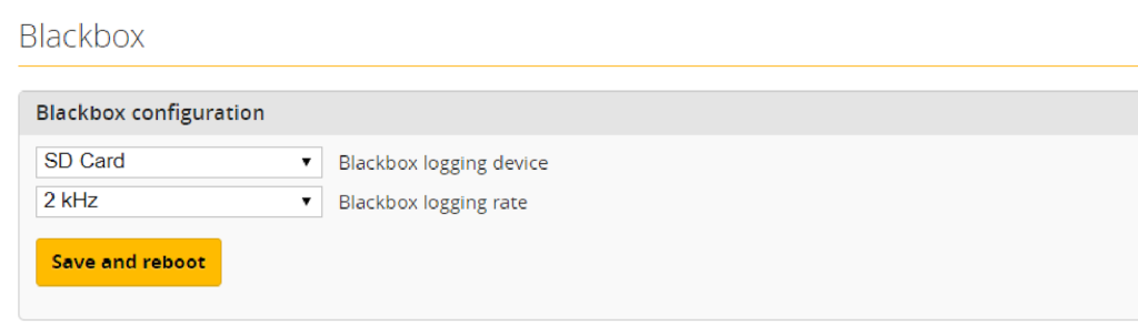
Blackbox
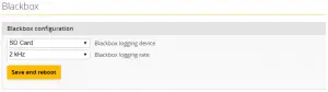
If you have enabled the Blackbox feature, go to the Blackbox tab on the left hand side of the configurator window. In the Blackbox tab, at the top, set the Blackbox logging device to “SD Card” (it should be set like this by default). Set the Blackbox Logging Rate to 2 kHz. To use Blackbox logging, insert a FAT-formatted SD card of 32 GB or smaller into the SD card slot on the Kakute F7. You can use the Betaflight Blackbox Log Viewer app to examine blackbox logs.
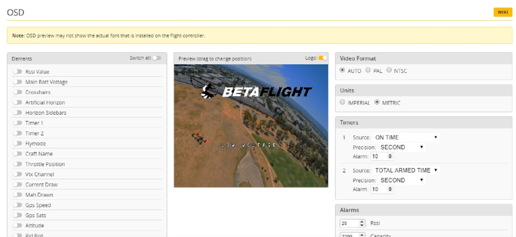
OSD
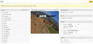
In the OSD tab, you can choose which values you want to see on screen while you are flying. Enable and disable individual elements using the Elements toggles on the left.
The Video Format section lets you choose whether your camera is NTSC or PAL. Betaflight defaults this value to Auto, but Auto sometimes picks wrong. If this happens, you might not see any OSD text, or the bottom of the OSD text might be off the bottom of the screen. In some cases, you won’t see any video at all—just the OSD. Because of this, we recommend manually setting the Video Format to NTSC or PAL depending on which type of FPV camera you have.
You can rearrange the individual OSD elements on screen by dragging them with your mouse in the “Preview” section of the window.
Some individual OSD Elements of note are:
Main Batt Voltage: This is probably the single most important element to use. Your battery must never go below 3.3 volts per cell under any circumstances, or it will suffer damage. For a 3S battery, this would be 3 times 3.3 = 9.9 volts. For a 4S battery, it would be 13.2 volts. Any time the battery goes below this level, it is likely being damaged, at least a little. More importantly, you will have very little power and may crash if you are doing aggressive maneuvers.
Although 3.3 volts is the recommended absolute minimum, you will get the best life out of your batteries if you keep the voltage above about 3.5 volts per cell—10.5 volts for 3S and 14.0 volts for 4S. If you are flying and you notice the battery going below this level, it might be time to land, or at least go easier on the throttle. If your batteries consistently drop to this level when you try to fly, it might be time to get new batteries.
When you are using the battery, its voltage will drop. This is referred to as “sag”. After you land, the battery will recover a small amount and its voltage will rise. Our recommendation is that, the battery should be at no less than 3.75 volts per cell—11.25 volts for a 3S and 15.0 volts for a 4S—after it has been allowed to rest at the end of a flight. If your batteries are consistently resting at below this level at the end of a day of flying, then you might be shortening their lifespan at least a little.
mAh Drawn: Although voltage is what ultimately determines whether a battery is being damaged, mAh may be a better way of deciding when to land. Because voltage sags when you raise the throttle and recovers when you lower the throttle, it can be hard to tell exactly how used-up the battery is. mAh is like a “gas gauge” for your battery. It shows how much capacity you have consumed, independent of other factors.
A good practice is to draw from a battery no more than about 80% of its rated mAh. So, a 1300 mAh battery would be able to deliver about 1000 to 1100 mAh. With a healthy battery and an honest battery rating, this will result in the battery resting at about 15.0 volts after flying. If you draw 80% of a battery’s rated capacity and it is resting at higher than 15.0 volts, the manufacturer might have under-rated its capacity. If the battery is resting at lower than 15.0 volts, the manufacturer might have over-rated its capacity. Also, remember that batteries lose capacity as they age. A battery that consistently fails to deliver 80% of its rated capacity without sagging below 14.0 volts might need retirement.
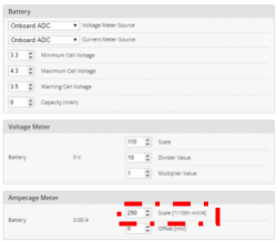
Current Sensor Calibration
The current sensor in your Kakute F7 has been set with a nominal calibration value. However, you may be able to improve the accuracy by performing a more precise calibration. We recommend that you record the mAh used at the end of your first few flights, then compare it to the mAh that your battery charger puts back into the batteries. Then adjust the Current Scale in the Power And Battery tab to compensate for any difference.
Here is an example:
- OSD shows 1100 mAh Drawn at the end of the flight.
- Charger shows 1000 mAh put back in to the battery.
- 1100 / 1000 = 1.10. The OSD is reading 10% high.
- Current Scale works backwards from how you might think. To make the OSD read lower, you make Current Scale larger. Since the OSD is reading 10% high, we need to INCREASE Current Scale by 10%. This will cause the OSD to read 10% lower.
- If the Current Scale was at 400, we will multiply it by 1.10 to add 10%, meaning the new value should be 440.
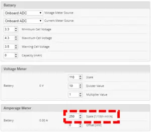
The mAh put back in by the battery will seldom perfectly match the mAh reported by the OSD, but by taking several measurements and averaging the results, you can usually get it reasonably close.
Using The OSD
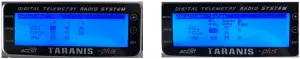
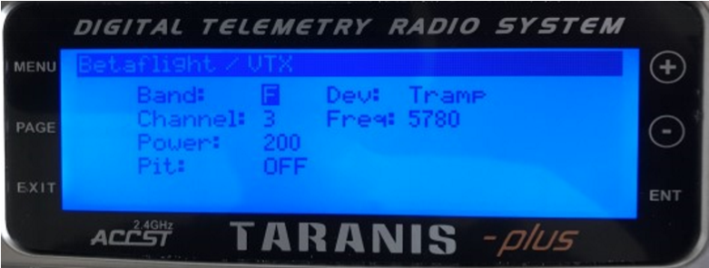
If you are using a Betaflight Flight Controller with Betaflight OSD, you can manage the Atlatl’s transmit power and channel from within the OSD.
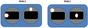
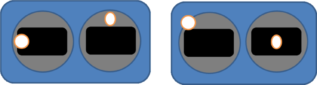
The graphics above show the stick command to bring up the OSD menu. The stick command is: throttle centered, yaw left, pitch forward. The exact stick command therefore depends on which mode your transmitter sticks are in.
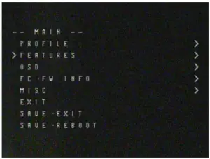
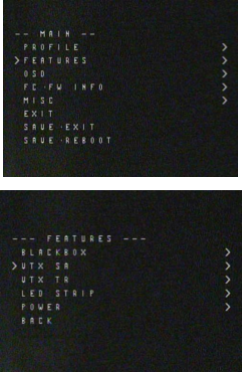
In the OSD menu, use pitch up/down to move the cursor between menu items. When a menu option has a > symbol to the right of it, this indicates that it contains a sub-menu. Roll right will enter the sub-menu. For example, in the screen to the right, moving the cursor to “Features” and then moving the roll stick to the right will enter the “Features” sub-menu.
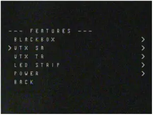
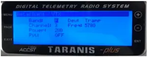
To manage the vTX, enter the “Features” menu. From there, enter “VTX SA” if you are using a SmartAudio device, or “VTX TR” if you are using an ImmersionRC Telemetry device.
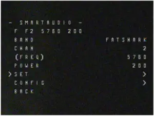
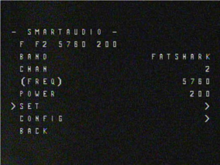
The screen to the right shows the current vTX settings. From here, you can change the frequency band, channel, and power level of the video transmitter. After making the changes, move the cursor to “Set” and press roll-right to confirm the settings.
Saving Your Configuration
Once you have finished building, configuring, and tuning your multirotor, it’s a good idea to back up your configuration so that you can restore it later. This is useful if you lose your quad, or if you damage your flight controller, or if you accidentally lock yourself out of your flight controller and must reset it to get back in.
Before we show you the right way to save and restore your configuration, let us warn you about the way. Betaflight and Cleanflight have a “save configuration” and “restore configuration” button.
Without going into too much detail, they have some significant drawbacks that mean we don’t recommend that you use them.
The correct way to save your configuration is as follows.
- Connect your Kakute to your PC by plugging in USB.
- Start the Betaflight GUI app.
- Go to the CLI tab.
- In the text box at the bottom of the CLI, type “diff all” and hit enter. This will cause the flight controller to display all configuration options that you have changed from the default values.
- In the lower-right corner of the configurator, click the “Save to File” button.
- Save the file somewhere you won’t lose it.
To restore your configuration, do this:
- Open the text file in your text editor.
- Highlight the entire contents of the file.
- Right-click in the text editor window and choose “Copy”.
- Connect your Kakute to your PC by plugging in USB.
- Start the Betaflight GUI app.
- Go to the CLI tab.
- Click the mouse once in the text box at the bottom of the CLI tab to place the cursor there.
- Instead of typing any commands, right-click in the text box and choose “Paste”.
- Press the Enter key on your keyboard. The pasted-in text will rapidly scroll past.
- Type “save” in the text box at the bottom of the screen.
- Press Enter. The flight controller will reboot and the configuration will be restored.
Additional Reference
Here are some links to additional videos to help you build your quadcopter successfully.
 Betaflight 3.3 Ultimate Setup Guide
https://www.youtube.com/watch?v=8vJCrHj9s6s
 How to Calibrate Your ESCs
https://www.youtube.com/watch?v=o3Mg-9M0l24
If you are using an analog protocol like One shot or Multi shot, calibrating your ESCs is mandatory. Most ESCs today support Dshot. If your ESCs support Dshot, you should use it, and you can skip this step.
 Failsafe
https://www.youtube.com/watch?v=dikr9oDzQqc
Failsafe is what happens when you fly too far away or your receiver gets disconnected from your flight controller. If you don’t configure failsafe, the quad could fly away, or it could crash into something… or someone.
DON’T FLY WITHOUT VERIFYING THAT FAILSAFE WORKS CORRECTLY.
To verify failsafe, remove your props, then plug in your battery and arm your copter. Then turn off your transmitter. Your motors should stop within 1 to 3 seconds at most.
If your motors don’t stop when you turn off your transmitter, DO NOT FLY YOUR MULTIROTOR UNDER ANY CIRCUMSTANCES.
Adjust PIDs / Rates / vTX from Taranis
If you have a FrSky Taranis radio and if you are using telemetry (such as SmartPort, F Port, or Crossfire), you can use your Taranis to change your PIDs and rates.
This is done by installing a piece of programming code called a Lua script on your Taranis. If you are also using SmartAudio, you can use a Lua script to change your vTX settings. This is the same as if you were using the Betaflight OSD, but it works without you having to put your goggles on.
Detailed instructions for how to do this are below:
 How to Upgrade Taranis to OpenTX 2.2 and Install Lua Scripts
https://www.youtube.com/playlist list=PLwoDb7WF6c8kLrGADjuxJUm5M2szXd_j8
Specifications
- Weight: 8g
Warranty and Return Policy
- Email:
Pinout Diagram
|
|
|
|
|
|
|
|
|
|
|
|
|
|
|
|
|
|
|
|
|
|
|
|
|
|
|
|
|
|
|
|
|
|
|
|
|
|
|
|
|
|
|
|
|
|
|
|
|
|
|
|
|
|
|
|
|
|
|
|
|
|
|
|
|
|
Installation Guide


Updating Betaflight Firmware
Before you can flash your board, you must get the drivers installed on your computer.

Here are the steps you will perform:
- Download the Virtual COM Port (VCP) driver installer from .a. To create a login at the STM site, first go to .
- Download the ImpulseRC Driver Fixer from .
The good news is, you do not need to repeat this process again. Sort of. You never need to install the drivers again on this computer, unless you reinstall the operating system for some reason. If you use another computer for the first time, you will need to install those drivers on it. Also, you may need to rerun the ImpulseRC Driver Fixer sometimes when you go to flash the board. If you try to flash the board and it fails, repeat steps 3 through 5 above.
- USB VCP is the port that is used to talk between the Kakute F7 and the Configurator GUI. MSP is the protocol that they use to talk to each other. If you turn off MSP on USB VCP, you will not be able to contact the board any more via the Configurator. You will have to re-flash the board and erase your configuration to get back into it. Suffice it to say, this is bad, and you shouldn’t do it.
- in the Peripherals column, choose either TBS SmartAudio or IRC Tramp, depending on which type of transmitter you are using.
Configuration
- SBUS. Spektrum Satellite receivers should use SPEKTRUM2048 or SPEKTRUM1024 depending on whether they are DSM2 or DSMX. FlySky receivers use iBus. Crossfire receivers use CRSF.
These are the most common serial receiver types that are likely to be encountered.
Before we show you the right way to save and restore your configuration, let us warn you about the
Additional Reference


https://www.youtube.com/playlist?
list=PLwoDb7WF6c8kLrGADjuxJUm5M2szXd_j8

Atlatl HV V2
5.8G FPV Video Transmitter![]()
User Manual & Installation Guide

Overview
Features
- Compatible with all major FPV receivers from vendors such as Fatshark, ImmersionRC, etc.
- Supports the standard 40-channel set: band A, B, E, Fatshark, and Raceband.
- SmartAudio input allows remote control by the flight controller. Change channel, transmit power, and more from Betaflight OSD, flight controller USB port, Taranis Lua Script, and more.
- All parameters are controllable via push-button on the side of the unit, for cases where SmartAudio is not used.
- MMCX connector is durable and easy to use. Rated for 100’s of mating cycles. Easy and quick antenna changes. No more ripped-off UFL connectors.
- LED indicators for channel, band, and power. Allows easy check of VTX parameters simply by glancing at the quad.
- Variable transmit power from 25 mW to 800 mW. Use 25 mW for a race and then easily switch to 800 mW for freestyle.
- 0.5 mW True Pit Mode allows you to power up safely without the risk of knocking other pilots out of the air.
- Built-in microphone, so you can listen to your motors while you fly, no matter how far away you fly.
- Standard 36mm form factor allows you to mount the Atlatl directly on your flight controller stack.
Specifications
- Output Power: 0.5 mW (pit mode), 25 mW, 200 mW, 500 mW, 800 mW
- Audio: 6.5 MHz Mono
- Antenna Connector: MMCX
- Input Voltage: 7 to 28 volts (2-6S LiPo) with absolute maximum of 42 volts
- Dimensions: 35x25x7mm (Includes USB height)
- Mounting Holes: Standard 30.5mm square to the center of holes
- Weight: 9.3g
Warranty and Return Policy
If you believe that your Atlatl is defective, please contact us. If we determine that the product is defective, it will be repaired or replaced at no charge to you. We may ask you to send your Atlatl to our service center for examination or repair. Shipping costs are your responsibility. Returned items should include the original packaging and all accessories. If the product is damaged or defective, we will repair or replace it. Refunds are only given when a product is lost by the shipping company. The refund amount is limited to the price of the product. Shipping costs are never refundable.
Contact us at:
• Email: [email protected]
• Facebook Page: Holybro
Pinout Diagram and Channel Table
| Pin | Color | Function |
| B+ | Red | Input Voltage (7-42 volts) |
| G | Black | Ground |
| VI | Yellow | Video In (from a camera) |
| T | Blue | SmartAudio Input |
| 1 | 2 | 3 | 4 | 5 | 6 | 7 | 8 | ||
| A | Band A | 5865 | 5845 | 5825 | 5805 | 5785 | 5765 | 5745 | 5725 |
| 13 | Band B | 5733 | 5752 | 5771 | 5790 | 5809 | 5828 | 5847 | 5866 |
| E | Band E | 5705 | 5685 | 5665 | 5645 | 5885 | 5905 | 5925 | 5945 |
| F | IRC/FS | 5740 | 5760 | 5780 | 5800 | 5820 | 5840 | 5860 | 5880 |
| C | RaceBand | 5658 | 5695 | 5732 | 5769 | 5806 | 5843 | 5880 | 5917 |
Installation Guide
The Atlatl is designed to be installed in your flight controller stack. It can be installed above or below your FC using the same type of M3 nylon standoffs that are used to mount the FC itself. Wiring up the Atlatl is not complicated.
- Insert the JST-GH connector into the receptacle on the Atlatl.
- Solder the red wire to the voltage source for the Atlatl. The Atlatl can run off of battery voltage directly (7 to 28 volts, 2S to 6S). There is no need to run the Atlatl off of a voltage regulator and in fact, this sometimes produces worse video quality. We recommend powering the Atlatl directly from battery voltage and only try regulator or filtered supply if you have video noise.
- Solder the black wire to a ground pad. Video noise will be minimized if you solder your Atlatl ground wire and your FPV camera’s ground wire to the same pad. Twist them together and tin them before soldering them both to the same pad.
- Connect the Atlatl’s yellow wire to the video signal wire of your FPV camera. The camera’s video wire will usually be yellow as well. You can directly solder the two wires together, or you might have a PDB or FC with a “Video In” and “Video Out” pad. In that case, solder the camera’s video wire to “Video In” and Atlatl’s video wire to “Video Out”.
- The Atlatl can be remote-controlled using the SmartAudio protocol. This is the recommended use of the Atlatl. To use this feature, solder the Atlatl’s blue wire to the TX pad of the UART on your flight controller that will be used for this feature. See your FC’s documentation for help deciding which UART to use.
- In Betaflight or Cleanflight, go to the Ports tab. Enable SmartPort protocol on the UART that you are using to remote-control the Atlatl (the UART whose TX pad you soldered the blue wire to). Do not enable any other function on this UART. Each UART must have only one function active at a time.
![]()
Using The OSD
If you are using a Betaflight Flight Controller with Betaflight OSD, you can manage Atlatl’s transmit power and channel from within the OSD.
![]()
The graphics above show the stick command to bring up the OSD menu. The stick command is throttle centered, yaw left, pitch forward. The exact stick command, therefore, depends on which mode your transmitter sticks are in.
In the OSD menu, use pitch up/down to move the cursor between menu items. When a menu option has a > symbol to the right of it, this indicates that it contains a sub-menu. Rollright will enter the sub-menu. For example, in the screen to the right, moving the cursor to “Features” and then moving the roll stick to the right will enter the “Features” sub-menu.
![]()
To manage the Atlatl, enter the “Features” menu. From there, enter “VTX SA”
![]() The screen to the right shows the current vTX settings. From here, you can change the frequency band, channel, and power level of the video transmitter. After making the changes, move the cursor to “Set” and press roll-right to confirm the settings.
The screen to the right shows the current vTX settings. From here, you can change the frequency band, channel, and power level of the video transmitter. After making the changes, move the cursor to “Set” and press roll-right to confirm the settings.
Functions
Channel-Change Button
The Atlatl can be configured via either SmartAudio or the channel change button. If you have SmartAudio enabled in Betaflight, then the button cannot be used. If you prefer to use the button, you must disable SmartAudio in Betaflight.
Here is how to use the button:
- To change the channel, hold down the button for 2 seconds until the Channel LED blinks. You are now in channel select mode. Press the button one time to advance the channel.
- To change the band, first, go into channel select mode. From channel select mode, hold down the button for 2 seconds until the Band LED blinks. You are now in band select mode. Press the button one time to advance through the bands.
- To change power, first, go into band select mode. From band select mode, hold down the button for 2 seconds until the Power LED blinks. You are now in power select mode. Press the button one time to advance through the power options.
- From power select mode, hold down the button for 2 seconds to exit configuration and return to normal operation.
Pit Mode
Have you ever powered up your copter, only to have one of your friends start shouting and crash? Your video transmitter was on the same channel he was on, or even a nearby channel, and your signal were so loud that it overpowered his own. This is commonly referred to as being “stomped on”, and it’s a big problem any time more than one person is flying together. Even if you are not on the same channel as somebody else, you can stomp on them if you are too close to them Pit Mode helps to prevent you from stomping on other pilots. When the transmitter is in Pit Mode, it will only transmit at very low power. Within a short distance, you will be able to see your own copter’s transmission, but other pilots who are further away, won’t be affected.
To put the Atlatl into Pit Mode, hold down the button while you plug in your battery. This will cause the Atlatl to power up in Pit Mode. If you’re flying with friends, it’s a good idea to make a habit of this, to ensure that you don’t stomp on any of them when you power up.
When the Atlatl is in Pit Mode, you can change the channel, band, and power settings. These will take effect when you power cycles the board. This allows you to configure the Atlatl without stomping on other pilots who are already in the air.
Always follow best practices for frequency assignment when flying with other pilots. Never power up near other pilots, even if you think the channel is clear. Neverland your copter near to other pilots either. Always power up, take off, and land, at least 20-30 feet away from pilots who are flying.