GEEETECH Prusa Desktop 3D Printer Instruction Manual
SUPPORT
Thanks for choosing Geeetech, we strive to provide a satisfied and pleasant shopping experience for you, but we do understand there may be some questions you may encounter in using our product. If so, you can contact us directly or post on our forum, our technique staff will help you resolve it. For more detailed information, you can also visit Geeetech wiki from our home page.
For detailed instructions, please download here:
For detailed building videos, please check at YouTube:
Subscribe our YouTube channel for more videos.
https://www.youtube.com/user/geeetech
Join our geeetech 3D printer user club.
Feel free to drop a line at [email protected] .
Copyright Declaration
The copyright of this manual belongs to the Shenzhen GETECH CO., LTD. (hereinafter referred to as the “Geeetech”), and all rights reserved. No part of this specification should be reproduced or extracted in any forms or means without the prior written consent of Geeetech by any company and individuals.
For More Geeetech Products
If you are interested in the technology of 3 D printing, flight control and U-home, welcome to Geeetech, we have series of made-up products, main boards, modules and a variety of peripherals for you. Or if you are looking for relevant information or technical support, please login our Forum where you can find anything you want about open source. To know more about our new products, please visit www.geeetech.com , we will serve you wholeheartedly.
SAFETY INSTRUCTIONS
Building the printer will require a certain amount of physical dexterity, common sense and a thorough understanding of what you are doing. We have provided detailed instructions to help you assemble it easily, please download at geeetech.com.
However ultimately we cannot be responsible for your health and safety whilst building or operating the printer, with that in mind be sure you are confident with what you are doing prior to commencing with building or buying. Read the entire manual to enable you to make an informed decision. Building and operating involves electricity, so all necessary precautions should be taken and adhered to, the printer runs on 24V supplied by a certified power supply, so you shouldn’t ever have to get involved with anything over 24V but bear in mind there can still be high currents involved and even at 24V they shouldn’t be taken lightly. High temperatures are involved with 3D Printing, the Extrusion nozzle of the hot end can run about 230°C, the heated bed runs 110°C and the molten plastic extruded will initially be at around 200°C, so special care and attention should be made when handling these parts of the printer during operation.
We wouldn’t recommend leaving your printer running unattended, or at least until you are confident to do so. We cannot be held responsible for any loss, damage, threat, hurt or other negligent result from either building or using the printer.
INTRODUCTION:
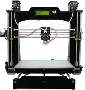
Geeetech Prusa I3 M201 is the 2-in-1-out version of our latest Prusa I3 series 3D printer. This is a fused filament fabrication printer, easy to use and also designed for DIYers and professionals alike. The M201 features our newly engineered the 2-in-1-out switchable hotend, that feeds 2 filaments through one nozzle. With the new 2-in-1-out hotend the M201 can work like a color palette, providing a new level of expression with your prints allowing you to create alternating colors, blending color and gradients. In order to achieve this we optimized the firmware that is driven by our newly developed GTM32 pro Vb control system, which is based on the STM32 processor and paired with the ARM Coretex M3, running a dominant frequency of 72MHz, greatly improving the overall printing performance. We added a new feature, the Mixer, to the interface to control the percentage of the feed rate of the two filaments. To prevent the extruder from becoming jammed from over fused filament detained in the barrel we added an over fused protect feature or OFP which is enabled by default and keeps things running smooth. This M201 3D printer maintains DIY property, with which you can unleash your creativity to refit or modify it as you like. This kit is just the beginning; you can get more out of it.
PACKAGE LIST:
This list includes all the parts required to assemble your Geeetech Prusa I3 M201 3D Printer. After you received your package, please check if all the parts listed are included. Also make sure all the components are in good condition and not damaged during shipping. If anything is missing please contact with our customer service straight away, provide us the NO. , Name, and Qty.
| No. | Name | Specifications | Qty | Pic. | |||||||||||||
| 1 | Smooth Rod | D8*L340mm
Z axis |
2 | 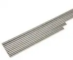 |
|||||||||||||
| 2 | Smooth Rod | D8*L470mm
X axis |
2 | ||||||||||||||
| 3 | Smooth Rod | D8*L420mm
Y axis |
2 | ||||||||||||||
| 4 | Lead screw | M8*L320mm Z axis | 2 | ||||||||||||||
| 5 | Threaded Rod | M10xL450mm Y axis | 2 | ||||||||||||||
| 6 | M2.5
Washers |
M2.5 | 8 | ||||||||||||||
| 7 | M3
Washers |
M3 | 110 |  |
|||||||||||||
| 8 | M4
Washers |
M4 | 30 | ||||||||||||||
| 9 | M10
Washers |
M10 | 15 | ||||||||||||||
| 10 | Spring washer | M10 | 8 |  |
|||||||||||||
| 11 | Hex Nut | M2.5 | 5 | 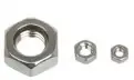 |
|||||||||||||
| 12 | Hex Nut | M3 | 15 | ||||||||||||||
| 12A | Hex Nut | M4 | 18 | ||||||||||||||
| 13 | Hex Nut | M10 | 13 | ||||||||||||||
| 14 | Lock nut | M4 | 4 |  |
|||||||||||||
| 15 | Wing nut | M3 | 8 |  |
|||||||||||||
| 16 | Z-axis nut | TR808 | 2 |  |
|||||||||||||
| 17 | Square nut | M3 | 40 |  |
|||||||||||||
| 18 | Hex Counter- sunk-head
screw |
M3x16 mm | 3 |  |
|||||||||||||
| 19 | Hex Counter- sunk-head screw | M3x30 mm | 5 |  |
|||||||||||||
| 20 | Screw | M2.5x8mm | 3 | 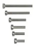 |
|||||||||||||
| 21 | Screw | M2.5x16mm | 5 | ||||||||||||||
| 22 | Screw | M3x6mm | 37 | ||||||||||||||
| 23 | Screw | M3x8mm | 3 | ||||||||||||||
| 24 | Screw | M3x10mm | 5 | ||||||||||||||
| 25 | Screw | M3x12mm | 25 | ||||||||||||||
| 26 | Screw | M3x16mm | 40 | ||||||||||||||
| 27 | Screw | M3x20mm | 10 | ||||||||||||||
| 28 | Screw | M3x25mm | 5 | ||||||||||||||
| 29 | Screw | M3x30mm | 2 | 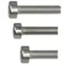 |
|||||||||||||
| 30 | Screw | M3x40mm | 2 | ||||||||||||||
| 31 | Screw | M3x45mm | 2 | ||||||||||||||
| 32 | Screw | M4x 6mm | 8 | ||||||||||||||
| 33 | Screw | M4x12mm | 13 | ||||||||||||||
| 34 | Screw | M4x16mm | 18 | ||||||||||||||
| 35 | Screw | M4x25mm | 4 | ||||||||||||||
| 36 | Spring | 4*20 | 6 |  |
|||||||||||||
| 37 | locking ring | M8 / With screw | 8 |  |
|||||||||||||
| 38 | Belt mount | Sheet metal part | 1 |  |
|||||||||||||
| 39 | Linear Bearing | PCS8UU | 4 |  |
|||||||||||||
| 40 | Linear Bearing | LM8LUU | 2 |  |
|||||||||||||
| 41 | Linear Bearing | LMH8LUU | 2 |  |
|||||||||||||
| 42 | Driven wheel holder | Sheet metal part | 2 |  |
|||||||||||||
| 43 | Driving wheel | 2 |  |
||||||||||||||
| 44 | Ball Bearing | MR84zz
(Placed in No.43) |
4 |  |
|||||||||||||
| 45 | Pulley | 20 tooth Inner D5 | 2 |  |
|||||||||||||
| 46 | Timing Belts | 2GT
L=2.4 meters |
1 |  |
|||||||||||||
| 47 | Belt bracket | Plastic part | 1 | 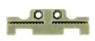 |
|||||||||||||
| 48 | Couplings | 5-8mm | 2 | 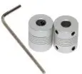 |
|||||||||||||
| 49 | Spacer | With Aircraft type end | 8 |  |
|||||||||||||
| 50 | Knob | For LCD | 1 |  |
|||||||||||||
| 51 | Fan | 40x40x10mm | 1 | 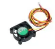 |
|||||||||||||
| 52 | Extension wire | 2-pin F-M | 1 |  |
|||||||||||||
| 53 | USB cord | A-B | 1 |  |
|||||||||||||
| 54 | End stop kit | 2-pin Blue, red and
black |
1 | 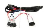 |
|||||||||||||
| 55 | Heat sink | 9*10*5mm | 5 |  |
|||||||||||||
| 56 | Sticker | 2 |  |
||||||||||||||
| 57 | Spiral Coil | 1 meter | 1 |  |
|||||||||||||
| 58 | Heatbed wire | 1 |  |
||||||||||||||
| 59 | Heatbed | 24V | 1 | 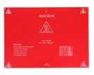 |
|||||||||||||
| 60 | Building platform | Alumina plate | 1 |  |
|||||||||||||
| 61 | Power supply Unit | AC Input: 115V/1.5A
230V/0.75A DC Output: 24V/10-15A |
1 | 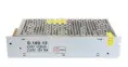 |
|||||||||||||
| 62 | 3D Power Cable | With plug | 1 | 
|
|||||||||||||
| 63 | Power Cable | Connect board to PSU | 1 | 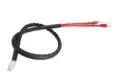 |
|||||||||||||
| 64 | Stepper motor | 4 | 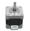 |
||||||||||||||
| 65 | 3-1 motor wire | For X/Y/ left Z motors | 1 | 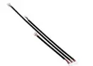 |
|||||||||||||
| 66 | motor wire | 700mm For Right Z
motor |
1 | 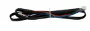 |
|||||||||||||
| 67 | Extruder | 2 |  |
||||||||||||||
| 68 | Extension board | 2 | 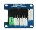 |
||||||||||||||
| 69 | Hex copper spacer | 4 |  |
||||||||||||||
| 70A | Extruder wire | 820mm | 1 |  |
|||||||||||||
| 70B | Extruder wire | 450mm | 1 |  |
|||||||||||||
| 71 | Extruder Motor wire | 6-4pin | 2 | 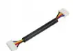 |
|||||||||||||
| 72 | Hotend | 2 in-1out | 1 | 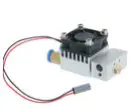 |
|||||||||||||
| 73 | LCD 2004 | LCD2004+
FPC Ribbon cable |
1 | 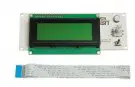 |
|||||||||||||
| 74 | Control board kit | GTM32 pro Vb +
5 A4988 |
1 set | 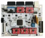 |
|||||||||||||
| 75 | Feeding pipe | PTFE
L=1meter |
2 |  |
|||||||||||||
| 76 | Nylon ties | 30 |  |
||||||||||||||
| Metal parts | |||||||||||||||||
| M1 | X- motor end | Sheet metal part | 1 | 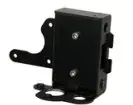 |
|||||||||||||
| M2 | X-idle end | Sheet metal part | 1 | 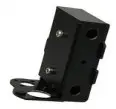 |
|||||||||||||
| M3 | X
Carriage |
Sheet metal part | 1 |  |
|||||||||||||
| M4 | Bearing Bracket | Sheet metal part | 4 |  |
|||||||||||||
| M5 | Extruder holder | Sheet metal part | 1 | 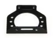 |
|||||||||||||
| M6 | Extension board cover | 2 | 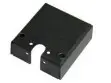 |
||||||||||||||
| Acrylic parts | |||||||||||||||||
| A1 | Main frame | I3E-01 | 1 | 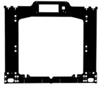 |
|||||||||||||
| A2 | Side panel (left ) | I3E-02 | 1 | 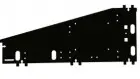 |
|||||||||||||
| A3 | Side panel (right) | I3E-03 | 1 | 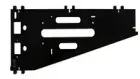 |
|||||||||||||
| A4 | Motor holder (left) | I3E-04 | 1 |  |
|||||||||||||
| A5 | Motor holder (right) | I3E-05 | 1 |  |
|||||||||||||
| A6 | Motor Holder support | I3E-06 | 3 |  |
|||||||||||||
| A7 | Motor Holder support | I3E-07 | 1 |  |
|||||||||||||
| A8 | Z top mount | I3E-08 | 2 |  |
|||||||||||||
| A9 | Y axis Front support | I3E-09 | 1 |  |
|||||||||||||
| A10 | Y axis Front support | I3E-10 | 1 |  |
|||||||||||||
| A11 | Y axis Rear support | I3E-11 | 1 |  |
|||||||||||||
| A12 | Y axis Rear support | I3E-12 | 1 | 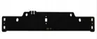 |
|||||||||||||
| A13 | Y motor holder | I3B1-13 | 1 |  |
|||||||||||||
| A14 | Connecting fender | I3E-14 | 2 |  |
|||||||||||||
| A15 | Building platform support | I3E-15 | 1 | 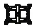 |
|||||||||||||
| A16 | Fan mount | I3E-16 | 1 |  |
|||||||||||||
| Free add-on | |||||||||||||||||
| 1 | Ejector pin | 1 |  |
||||||||||||||
| 2 | File | 1 |  |
||||||||||||||
| 3 | Screw- driver | 1 | 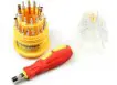 |
||||||||||||||
| 4 | Starter filament | 3 meters | 1 |  |
|||||||||||||
| 5 | Filament holder set | 1 |  |
||||||||||||||
| —— | ——— | ———— | —- | —————— | |||||||||||||

For detailed build instructions, please subscribe our YouTube for
videos.
https://www.youtube.com/user/geeetech/playlists
Download the build instruction PDF at
http://www.geeetech.com/geeetech-prusa-i3-m201-3d-printer-diy-kitp-965.html
GENERAL CARE AND MAINTENANCE
As with all the electronic equipment, it is important to keep your printer clean to extend its life. Regularly remove dust and debris with a microfiber cloth or compressed air. Dredge the tube and the nozzle after use every time to ensure fluent performance.
- Don’t leave the heaters on the printer turned on for a long periods of time when not used.
- Don’t leave your printer in shady and moist places, which may exacerbate the problems associated with erosion.
- The three axes of the Geeetech Prusa I3 M201 are lubricated with grease for smooth operation and can last for a long time. Grease may need to be re-applied to your printer to maintain smooth performance.
- Avoid positioning your power supply unit in such a way that the brick is hanging, pulling, or putting any unnecessary stress in the electrical wires and components.
![]()
Shenzhen Getech Technology Co., Ltd
Geeetech A10 3D Printer
User Manual (V0.01)
Thank you for choosing Geeetech products!
[Important] Please read the instruction manual carefully before using this machine.
Official site: https://www.geeetech.com/
Email us for technical support: https://www.geeetech.com/contact_us.htm
Facebook Group:

Facebook Group: https://www.facebook.com/groups/315127105604393/
Attention
Safety instructions
- Please switch to the correct local voltage (110V-220V) before turning on the printer. Be sure the switch is in the correct position or it will damage the power supply unit (PSU).
- Be sure all wires are correctly connected before turning on the printer.
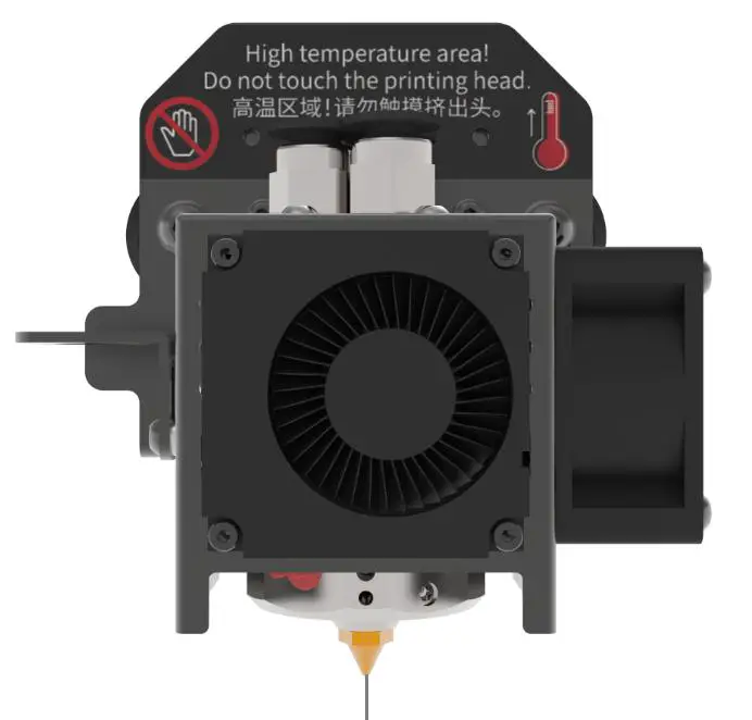
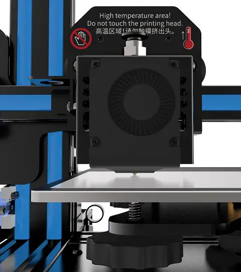
- Don’t touch the extruder head or hotbed when printing as they generate high temperature which may cause burn.
- Don’t leave the printer unattended when printing.
Factory test before delivery
In order to ensure quality, each printer is tested in the factory before delivery. As a result, there may be residue in the extruder head or on the hot bed, but it should not affect normal use. We provide the spare nozzle in the accessory kit just in case.
Parameters
1) Printing parameters
Printing technology: FDM
Printing volume: 220*220*260 mm3
Printing accuracy: 0.1~0.2mm
Positioning precision: X/Y: 0.011mm Z: 0.0025mm
Printing speed: 60mm/s
Nozzle quantity: 1-in-1-out single nozzle
Nozzle diameter: 0.4mm
Filament: Diameter 1.75mm;ABS/PLA, etc.
Environment temperature: 10℃-40℃
Operating system: Windows/Mac/Linux
Slicing software: Repetier-Host, EasyPrint 3D, Cura
File format: .STL/.Gcode
2) Electrical parameters
Power input: 115/230V AC,50/60Hz
Power output: DC24V-15A Max,360W
Connectivity: TF card, USB
Display screen: LCD2004 screen
3) Mechanical parameters
Printer size: 478x413x485mm3
Package size: 530x470x230mm3
Net weight: ~7.6kg
Gross weight: ~ 9.5kg
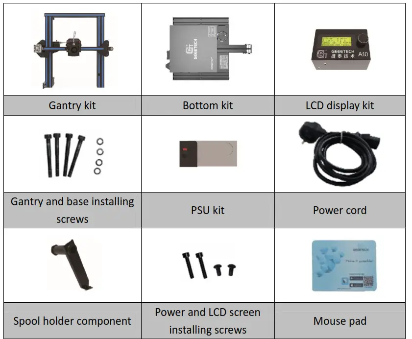
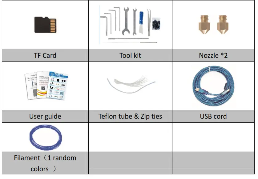
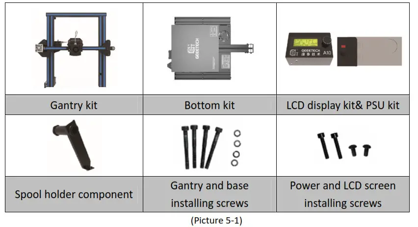
Packing list
Please check the parts/accessories when you receive the printer (As shown below). If any spare parts are missing, please contact your sales representative.
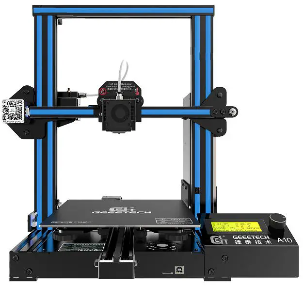
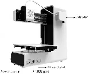
Machine Overview
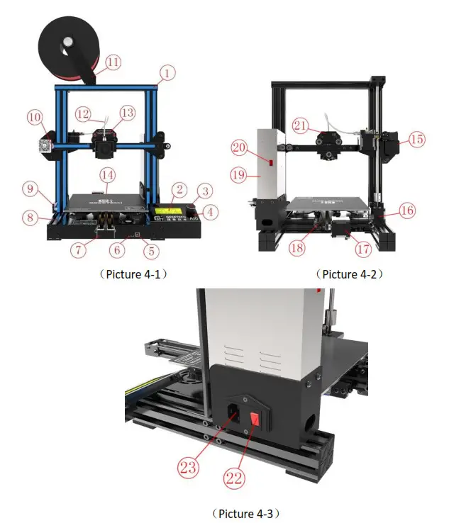
① Gantry kit;②LCD2004 screen;③Knob;④Reset button;⑤USB port; ⑥TF card slot;⑦Y axis;⑧Bottom kit;⑨Z axis end stop;⑩X axis end stop; ⑪Spool holder component;⑫Teflon tube;⑬Extruder head;⑭Hot bed;⑮X axis motor; ⑯Z axis motor;⑰Y axis motor;⑱Y axis end stop;⑲PSU;⑳Power voltage selector switch; ㉑Extruder wire connector;㉒Power switch;㉓Power socket
Assembling
Assembling the mainframe
The mainframe consists of the following components: Gantry kit, bottom kit, LCD display kit, PSU kit, Spool holder component, and its associated screws.
See picture (5-1)
The gantry and bottom frames are assembled from the bottom of the machine with 4 M5x45 screws and 4 spring washers M5. See picture (5-2).
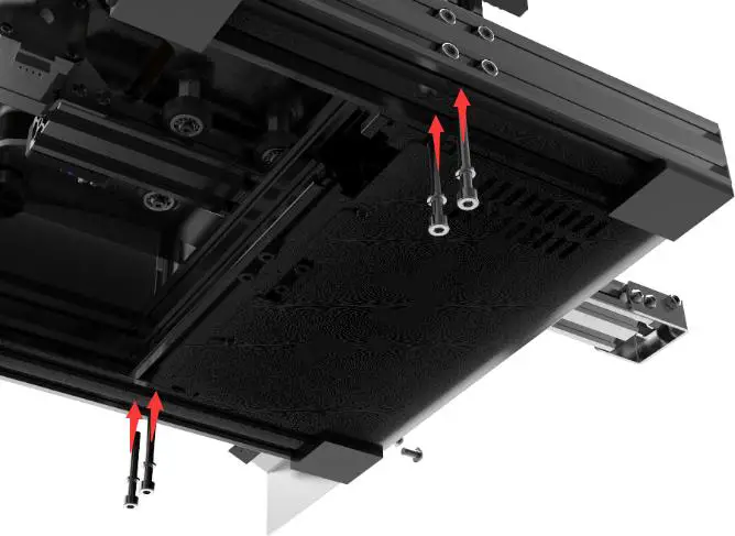
(Picture 5-2)
Fix the PSU to the gantry frame with 2 M4x20 screws. See picture (5-3).
(Picture5-3)
Fix the LCD to the correct holes on the right side of the base with 2 M5x10 screws. See picture (5-4).

(Picture 5-4)
Assemble filament holder and attach to the top of the frame closing to the extruder side, with 2pcs M3x6 screws and 2 T- nuts M3, as shown picture (5-5).
(Picture 5-5)
Wire connection
Insert the Teflon tube into the quick-insert connector. Details see picture (5-6).
(Picture 5-6)
Insert the LCD cable into LCD socket behind the LCD screen. See picture (5-7).
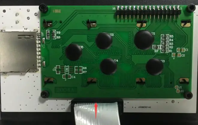
(Picture 5-7)
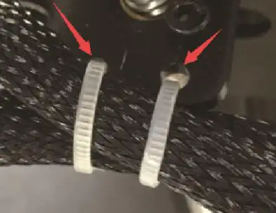
Connect two sets of power cables (note: can be connected arbitrarily without order) See picture (5-8).
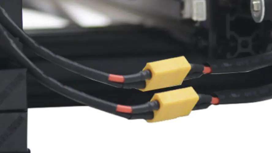
(Picture 5-8)
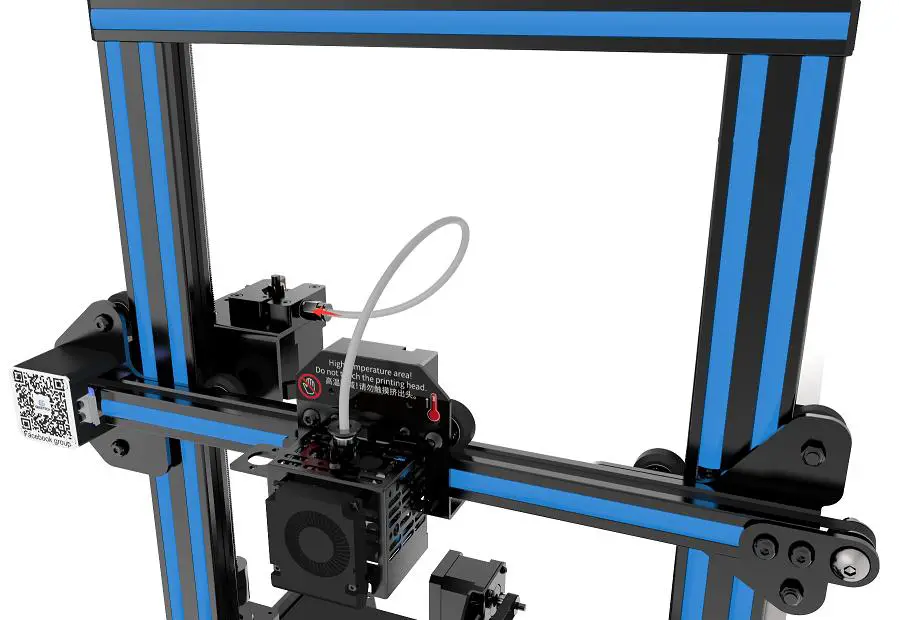
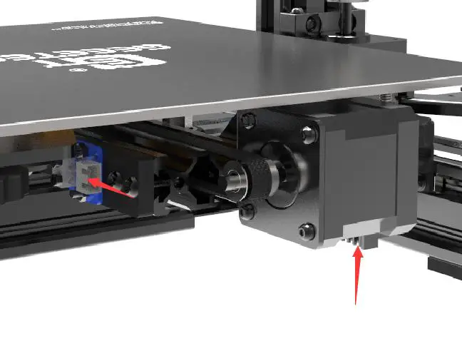
Plug the extruder cables into the socket of the extruder head adapter plate, and the buckle must be fastened. See picture (5-9)
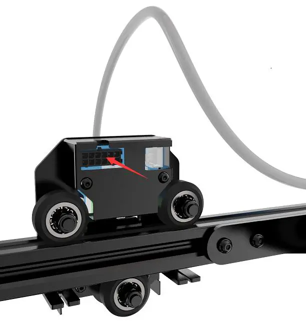
(Picture 5-9)
Connect the motor wires of E0. See picture (5-10).
(Picture 5-10)
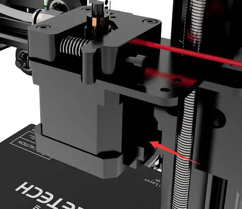
Then the extruder wire and the motor extruder wire are fixed into the small hole on the backside of the lead screw with the Cable tie to avoid the wire harness touching the model during printing. In addition, the position the harness fixed needs to reserve the length of the Z-axis at the maximum height. See picture (5-11).
(Picture 5-11)
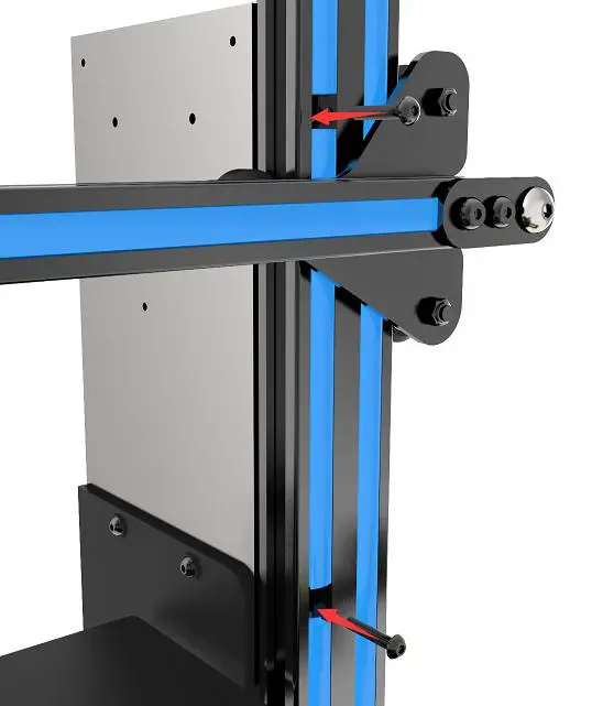
Connect the X-axis motor and the X-axis limit switch wire. See picture (5-12).
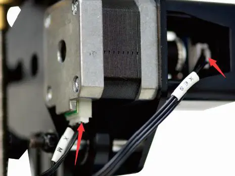
(Picture 5-12)
Connect the Y-axis motor and the Y-axis limit switch wire. See picture (5-13).
(Picture 5-13)
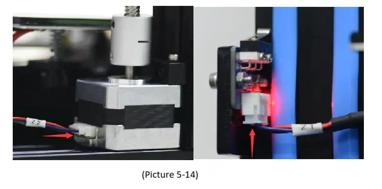
Connect the Z-axis motor and the Z-axis limit switch wire. See picture (5-14).
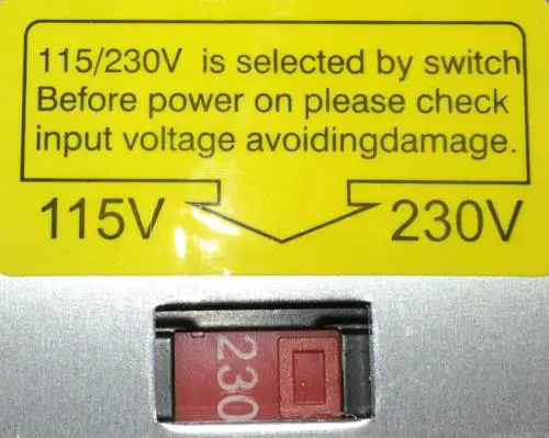
Check the power input mode
The factory default voltage is 230V. You need to choose the correct voltage according to your local standard requirement. See picture (5-15)
Note: Be sure the voltage is switched to the correct one.
(Picture 5-15)
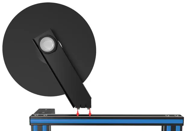
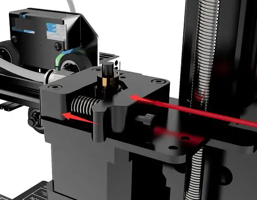
Check the filament
Put the filament on the spool holder. Please pay attention to the feeding direction of the filament. As shown by the arrow in (5-16).
![]()
Press down the lever handle of the extruder and insert the filament into the feeding tube until it reaches the extruder head. Since the filament is bent, so you need to straighten the front of the filament by hand and sharpen them with diagonal pliers or scissors to make it easier to insert it into the head. See picture (5-17).
(Picture 5-17)
When print PLA, set the target nozzle temperature about 190-210℃. When the temp is stable, control the extruder filament feeding on LCD screen (“Move axis”), feed until there is molten material flowing from the nozzle.
Observe the nozzle, if there is no filament stuck and the filament is coming out smoothly, then stop filament feeding, clear the nozzle with tweezers. See picture (5-18).
(Picture 5-18)
First print
Level the print bed
The first layer is key to a successfully printed model. The factory default setting is a little high in order to avoid scratching the hotbed with the nozzle, so users need to adjust the distance between nozzle and hotbed again. After the first-time bed leveling, users don’t need to level the bed again.
1) Rough leveling
Home the printer first (“Prepare”> “Auto home”), then it shows the option “Level corners” on the LCD screen. Put a piece of A4 paper on the platform, click “Next corner”, the extruder head moves counterclockwise from the bottom left corner to the four corners of the platform. See picture (6-1).

(Picture 6-1)
When the extruder head moves to the left bottom, adjust the corresponding knob until the distance between the nozzle and bed is about the thickness of a piece of paper (about 0.1-0.2mm). Slide the paper back and forth to see if you feel a slight resistance. If yes, it means the leveling of this corner is finished and you can proceed to level the rest corners with the same method. See picture (6-2).
(Picture 6-2)
2) Accurate leveling
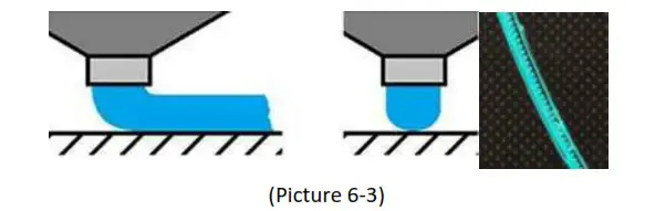
If you level the bed with A4 paper, the first layer may be too high, too low, or moderate. a. Too high: the distance between the nozzle and bed is too far, which may cause the filament to not stick or not stick well. See picture (6-3).
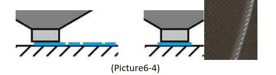
b. Too low: the distance between the nozzle and the bed is too close, which prevents the filament from coming out and causes the extruder gear to click, and even worse, scratch the nozzle on the bed. See picture (6-4).
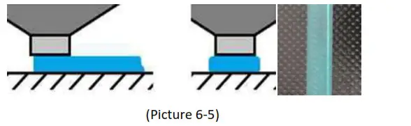
c. Moderate: Extrude the filament properly and evenly stick on the bed. See picture (6-5).
In the case of too low and too high, adjust the knobs under the platform till they are moderate. It may take some trial and error to achieve the best result. An example of good first layer, see picture (6-6).
(Picture 6-6)
Note:
If turn the knobs clockwise, the platform will rise, and vice versa.
Avoid the nozzle touching the bed; use a piece of A4 paper. Or it will scratch the bed.
For more details, please refer to this link: http://geeetech.com/forum/viewtopic.php?f=112&t=62296
TF card printing
Insert the TF card into the slot. See picture (6-7)
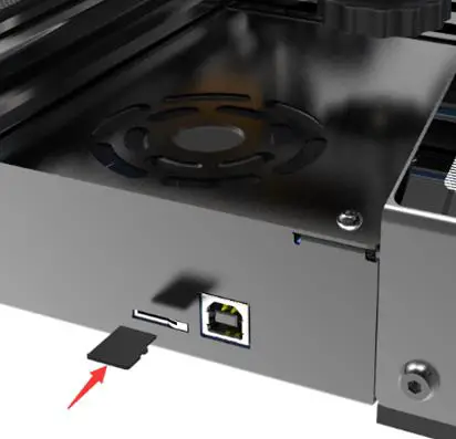 (Picture 6-7)
Press and rotate the knob to enter the main menu. Select the option of “Print from SD”. See picture (6-8).
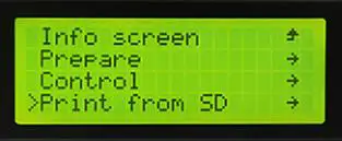
(Picture 6-8)
Choose the files in the TF card. See picture (6-9).
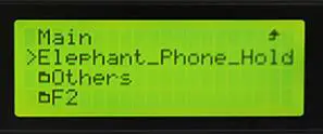
(Picture 6-9)
The printer will heat automatically. See picture (6-10).
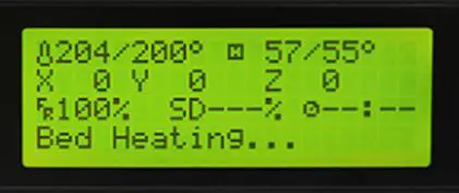
(Picture 6-10)
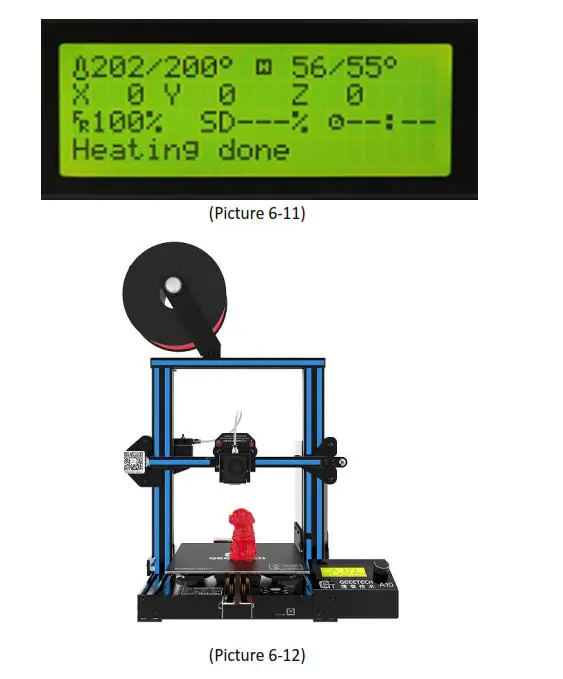
When heating done, the printer will start printing until the print is complete. See picture (6-11, 6-12).
Introduction to the LCD menu
Tree diagram
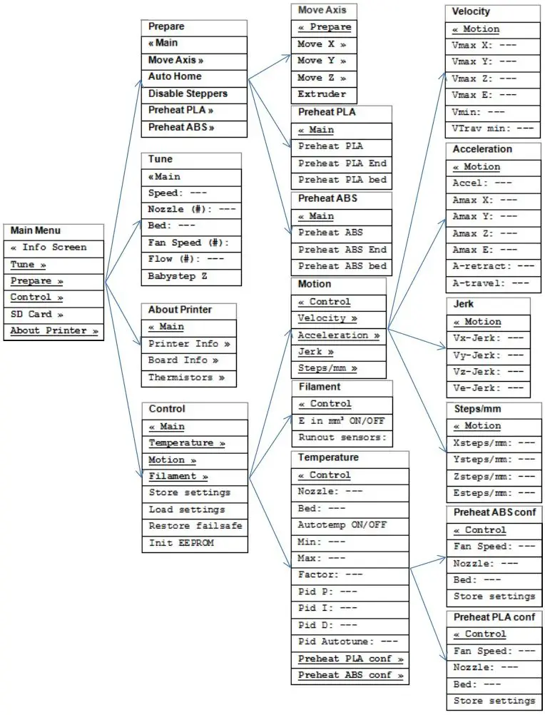
(Picture 7-1)
Main functions
LCD rotating knob:
• Press the knob: Confirm or enter the next menu.
• Rotate the knob: Roll the select options or change parameters.
LCD homepage, see picture (7-2)
1. Extruder temperature: Current temp/target temp
2. Hot bed temperature: Current temp/target temp
3. Current X,Y,Z axis value
4. Feed rate: Current print feeding speed
5. Current print time
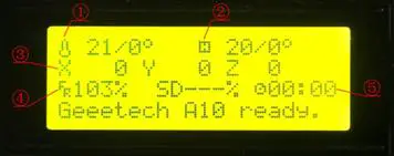
(Picture 7-2)
Note: Rotating the knob can change the printing feed rate during printing. We suggest users not changing the feed rate too much or it will make the motors to skip caused by too fast speed and affect the print quality.
Press the knob to enter the next menu (Picture 7-3):
- Prepare: Prepare and test the printer before normal operation
- Control: Printer temp and motion parameter setting
- Print from SD: TF/SD card printing(No SD card is shown when the card is not inserted)
- About Printer: The printer info
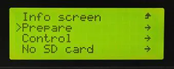
(Picture 7-3)
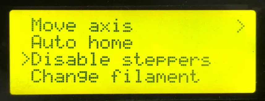
The main functions of Prepare menu (Picture 7-4, 7-5):
- Move axis: Move X/Y/Z axis and Extruder
- Auto home: X/Y/Z axis homing
- Disable steppers: Unlock motors
- Preheat PLA: Manually pre-heat the hotbed and extruder before printing PLA.
- Preheat ABS: Manually pre-heat the hotbed and extruder before printing ABS.
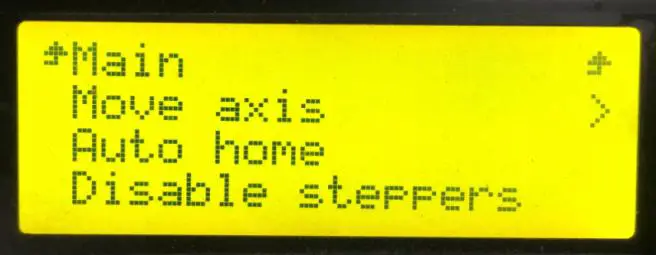
(Picture 7-4)
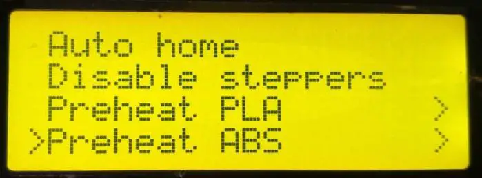
(Picture 7-5)
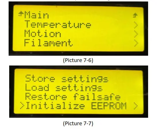
The main functions of Control menu (Picture 7-6, 7-7):
- Temperature: Change the temp of the hotbed and extruder in real-time during printing. Customize the temp of preheat PLA and preheat ABS.
- Motion: Motion parameter setting in firmware. After modification, choose “store memory” to save the change.
- Filament: Open or close filament detector; set filament diameter.
- Store settings: Save the parameters modified.
- Load settings: If you need to restore to the original settings, please choose this option.
- Restore failsafe: Restore factory setting.
- Initialize EEPROM: Initialize printer Settings
Test the motors’ function via LCD
Press the knob to enter the next menu; choose “Prepare”, choose “Auto home” to home the printer, see picture (7-8).
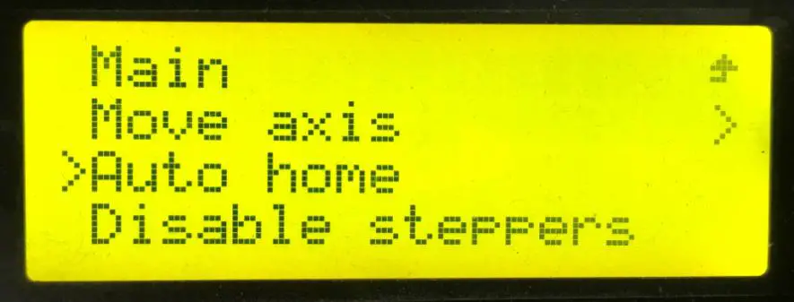
(Picture 7-8)
Choose “Move axis” to move motors. See picture (7-9)
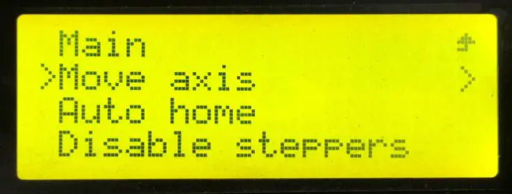
(Picture 7-9)
Choose from “Move X/Y/Z/Extruder “and rotate the knob to move them. See picture (7-10).
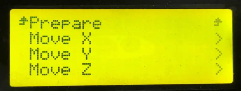
(Picture 7-10)
Choose “Move 1mm”, see picture (7-11).
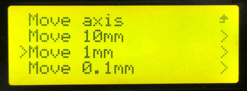
(Picture 7-11)
Note: we suggest using 1mm to test each axis.
After axis’ testing finished, if you want to unlock the motor, choose “Prepare>Disable steppers”, see picture (7-12).
(Picture 7-12)
When the motors are unlocked, you can move them by hand.
Software setting
Install driver
Two printing choices for A10: TF card printing and USB printing.
TF card printing: After leveling, insert the TF card into the slot, and choose a .gcode file to start printing.
USB printing: Connect the printer and computer with a USB cable to control the printer with slicing software such as Repetier-Host. Because of some unstable factors such as signal interference, the USB printing prone to fail. So we suggest choosing TF card printing.
The details of USB printing are as follows:
Firstly, turn on the printer, and connect the printer to computer with a USB cable. Normally, the computer will automatically search the install driver. The newest communication chip of A10 is CH340. See picture (8-1).
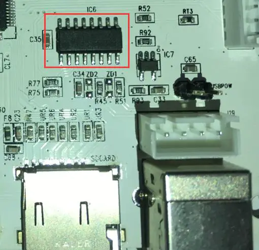
(Picture 8-1)
If it fails to automatically install the driver in computer, then check whether the driver is installed successfully or not. Click to choose “My computer>Property>Device manager”.
If it shows the exclamation mark as picture below (8-2), then you need manually install the driver.
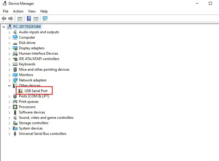
(Picture 8-2)
Download link for CH340:
https://www.geeetech.com/index.php?main_page=download&download_id=40
After the driver is installed, check the “Device manager” and see if it is same as the picture below (8-3). If so, it means the driver is successfully installed.

(Picture 8-3)
Install slicing software
Repetier-Host is the default slicing software here. Download address:
https://www.repetier.com/download-software/
• Set printer parameters
When Repetier-Host is installed, turn on the printer and open the Repetier-Host. Repetier-Host supports several languages. You can choose your native language from Config>Language (Picture 8-4 for details).
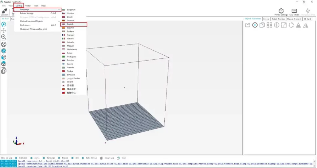
(Picture 8-4)
English interface for your reference (picture 8-5).
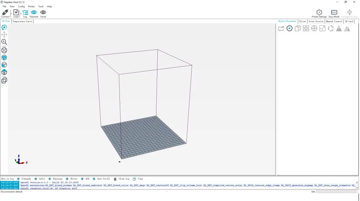
(Picture 8-5)
Using the Repetier-Host for the first time, printer parameters need to be configured before connecting. Click “Printer settings” on the top right corner, see picture (8-6).
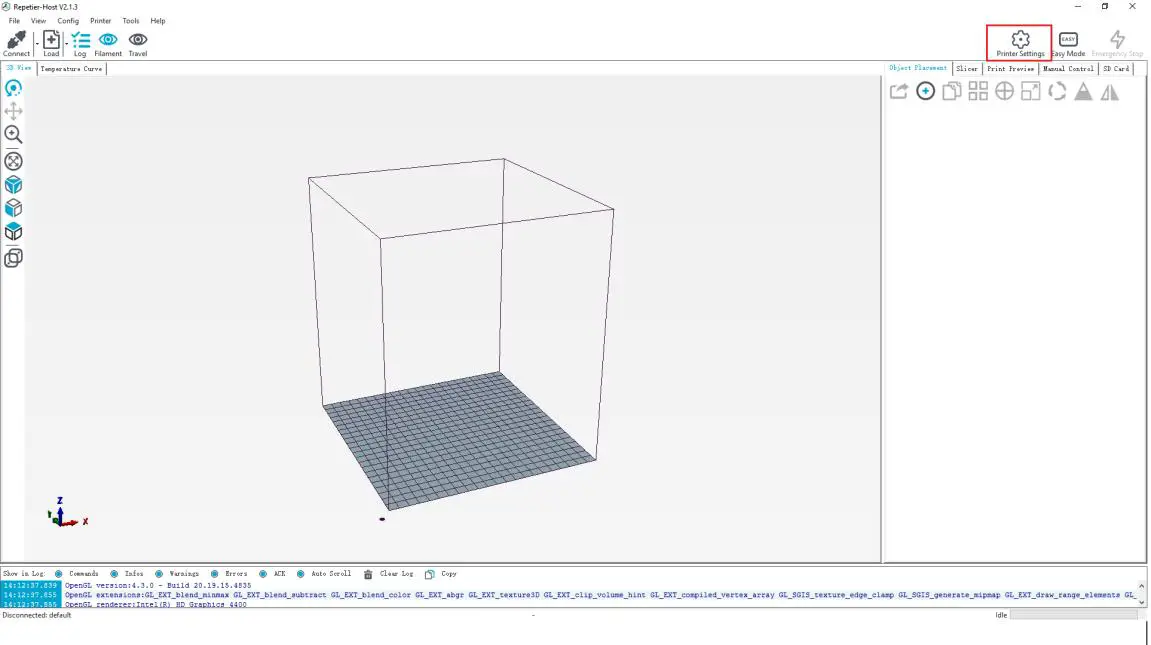
(Picture 8-6)
It pops up the content as the picture below. Write down the relevant info accordingly.
(Red box is the key content)
a. Connection dialog (Picture 8-7):
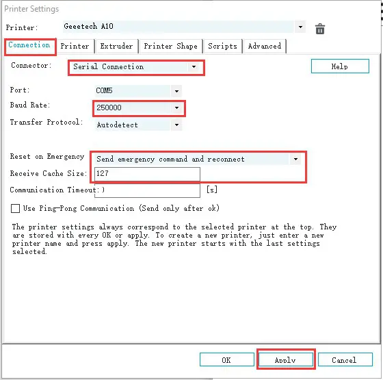
(Picture 8-7)
b. Printer dialog (Picture 8-8):
Do not check “Return to the parking position after the end of the task interruption” to prevent the machine from damaging the model after the end of printing.
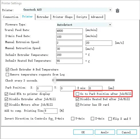
(Picture 8-8)
c. Extruder dialog (Picture 8-9):
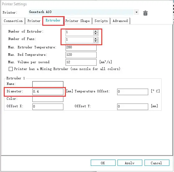
(Picture 8-9)
d. Printer shape dialog (Picture 8-10):
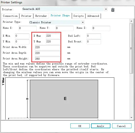
(Picture 8-10)
Now the printer parameters are set.
Note: If the operating system is Mac OS, Repetier Host baud rate is also set to 250,000.
• Set slicing parameters
After setting the printer parameters, click “Connect” on the top left corner. The color of the icon changed to green means the printer connects to the Repetier- Host successfully. Click it again to disconnect. See picture (8-11).
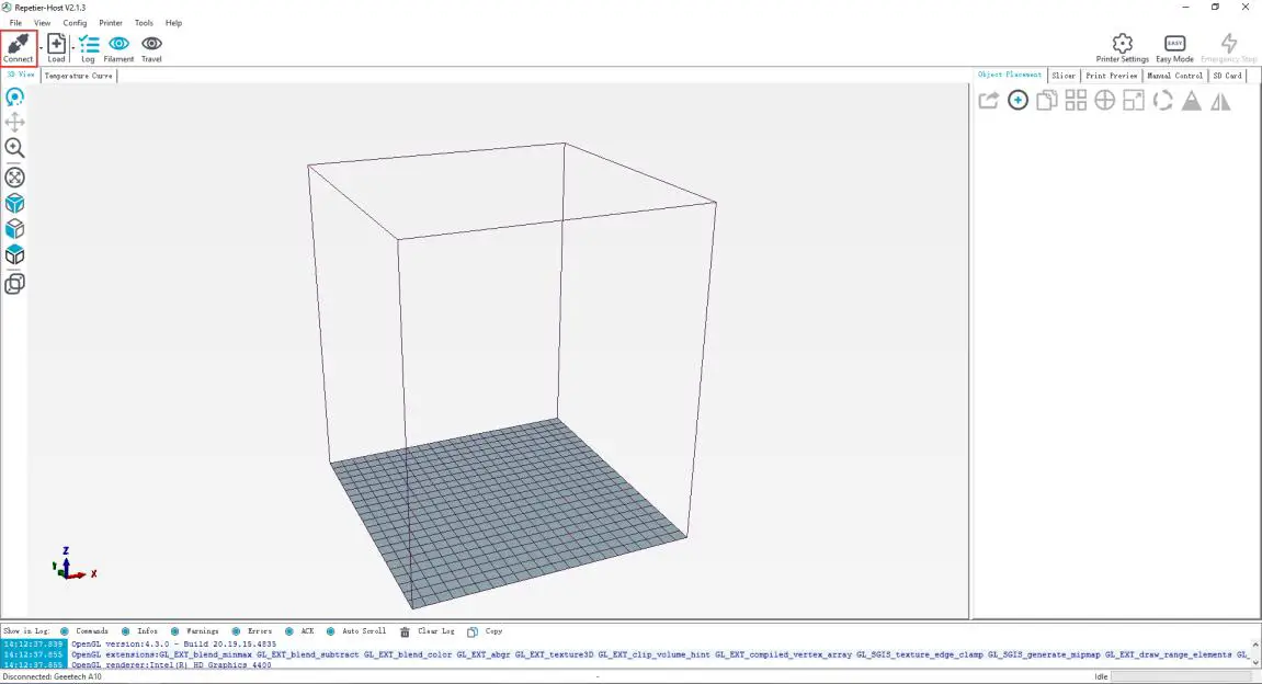
(Picture 8-11)
After successfully connected, choose “Slicer> CuraEngine” and open the configuration menu. See picture (8-12).
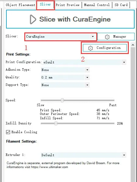
(Picture 8-12)
It pops up dialog as picture below (8-13):
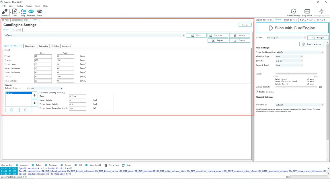
(Picture 8-13)
Printer parameters are important to print quality. Customers need to run tests to find the best parameters for their printers. Here we provide a configuration file for your reference (“Geeetech A10 PLA high.rcp”). You can import it according to the steps as follows. The following is an example of parameters for PLA (Picture 8-14):
Click “Print>Import”
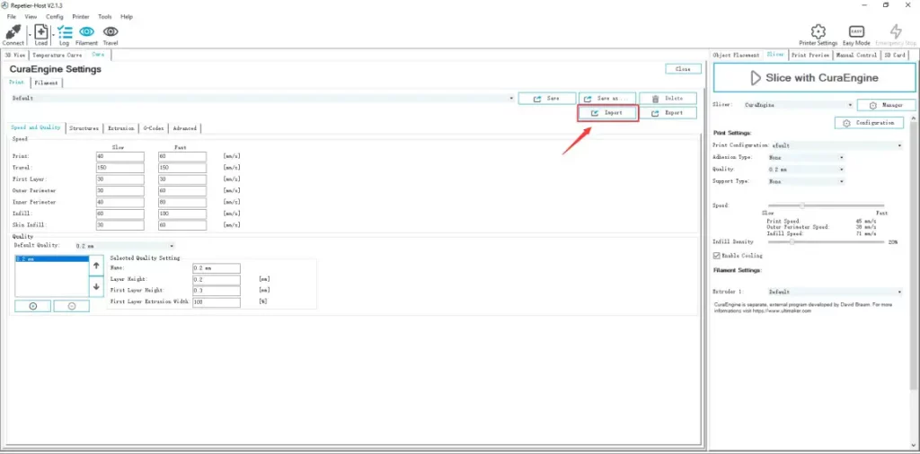
(Picture 8-14)
It pops up the dialog as below (Picture 8-15). Choose “Geeetech A10 PLA high.rcp” and open it.
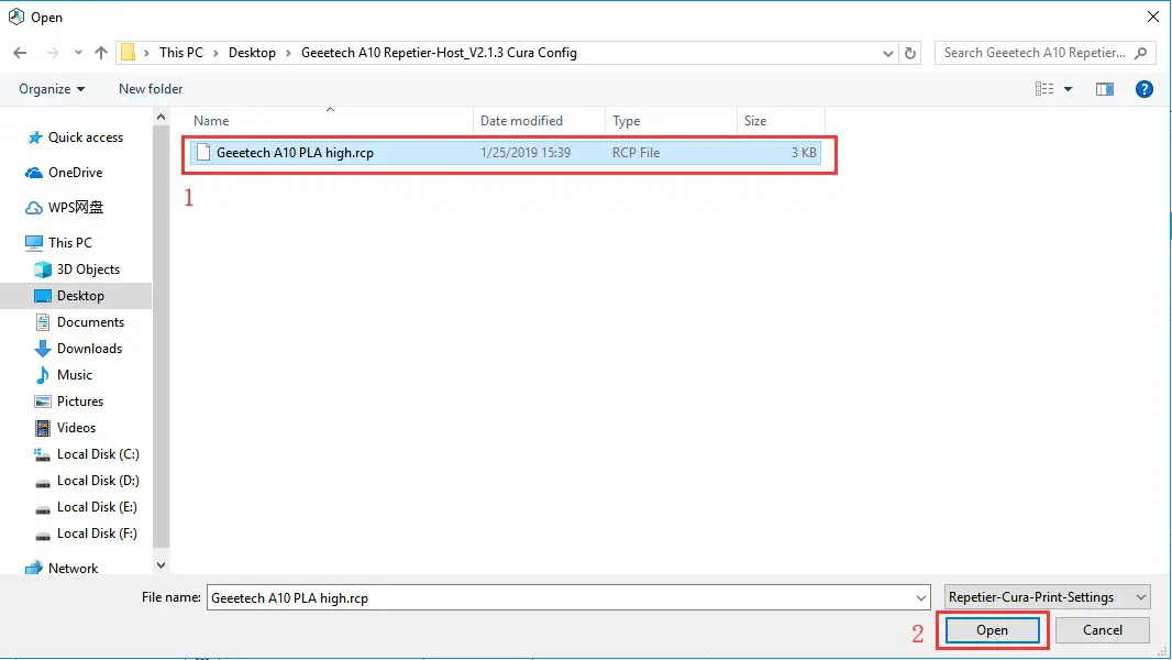
(Picture 8-15)
Now, the configuration file is imported, click “Save”. See picture (8-16).
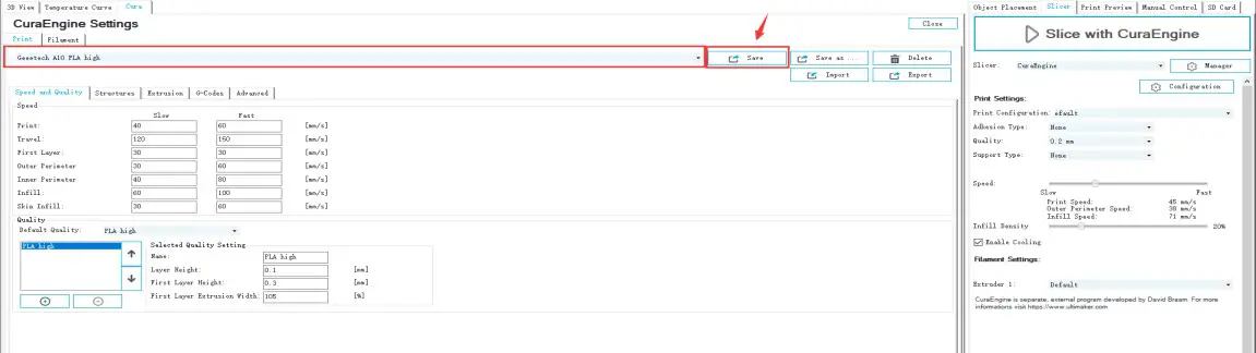
(Picture 8-16)
Click “Filament>Import”, see picture (8-17).
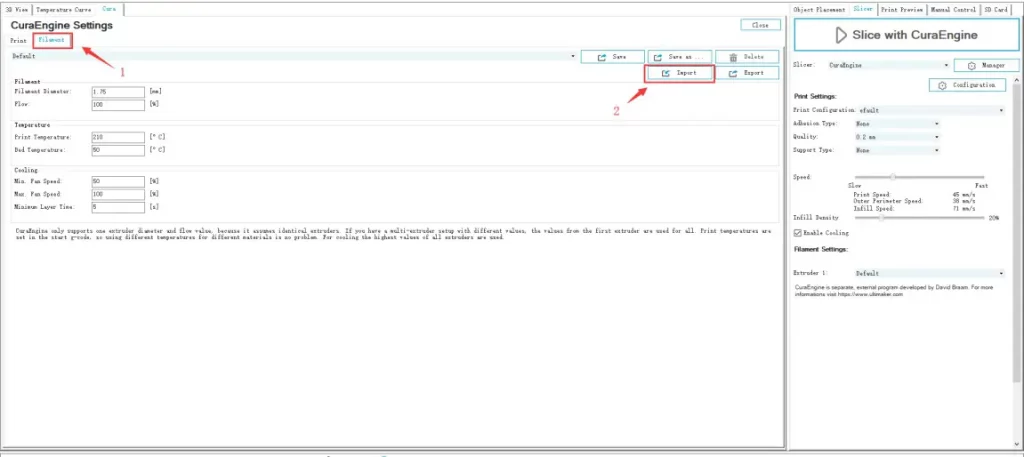
(Picture 8-17)
It pops up dialog as below (Picture 8-18); choose “Geeetech A10 PLA high fi.rcf”.
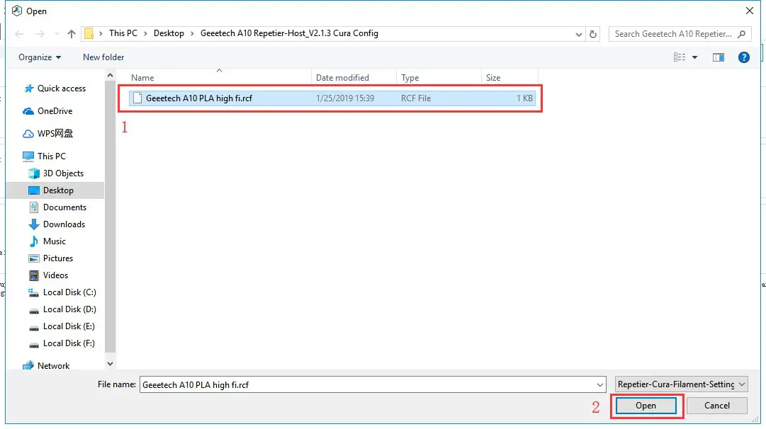
(Picture 8-18)
Now, the configuration file is imported. Click “Save”. See picture (8-19).
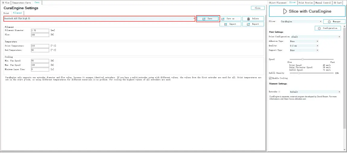
(Picture 8-19)
Choose “Geeetech A10 PLA high” as print configuration and “Geeetech A10 PLA high fi” as printing material setting. Details see picture (8-20) below.
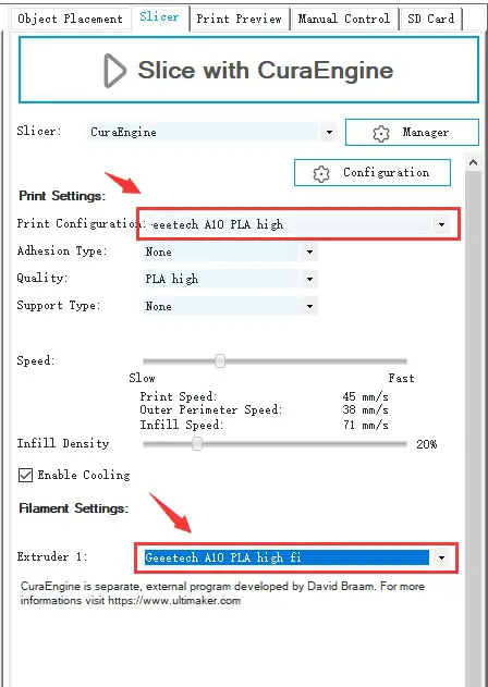
(Picture 8-20)
Now parameters setting are finished.
USB printing
You can start USB printing when the parameters setting are finished.
The model file format is .stl for 3D printer. You can download free models from websites such as thingiverse.com You can also design your own models.
Load the printing model
Open the Repetier-Host and click “load”. Choose a file and open it. See picture (8-21, 8-22).
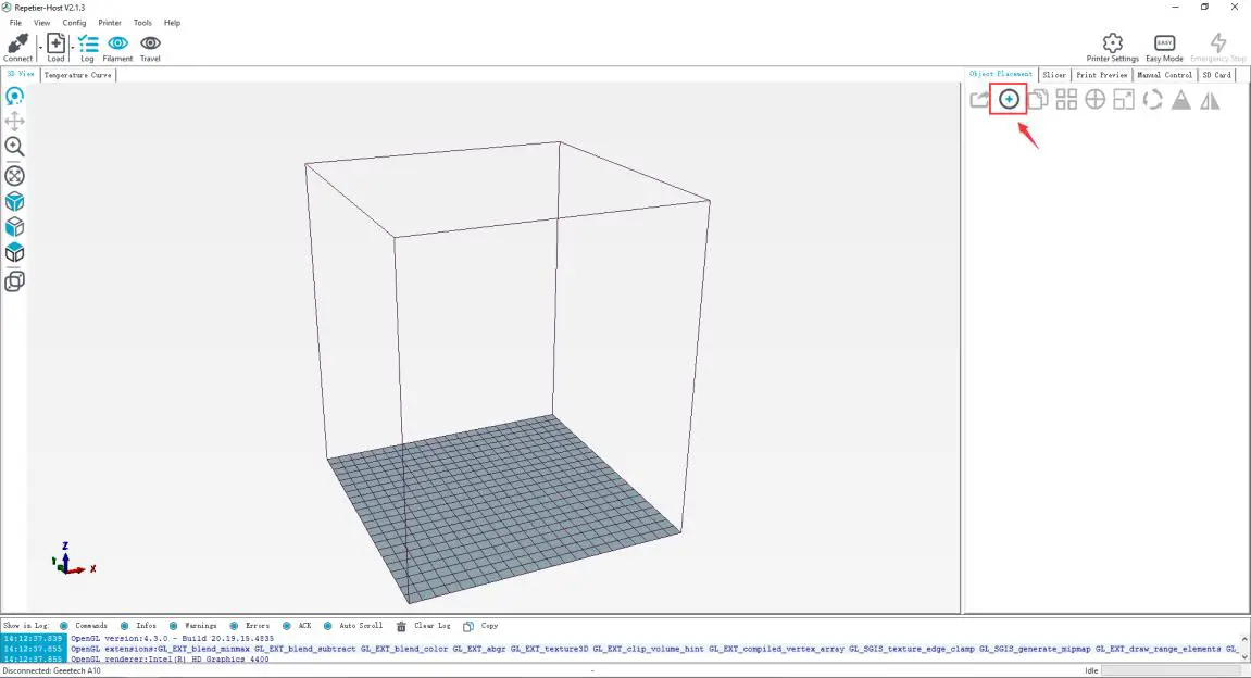
(Picture 8-21)
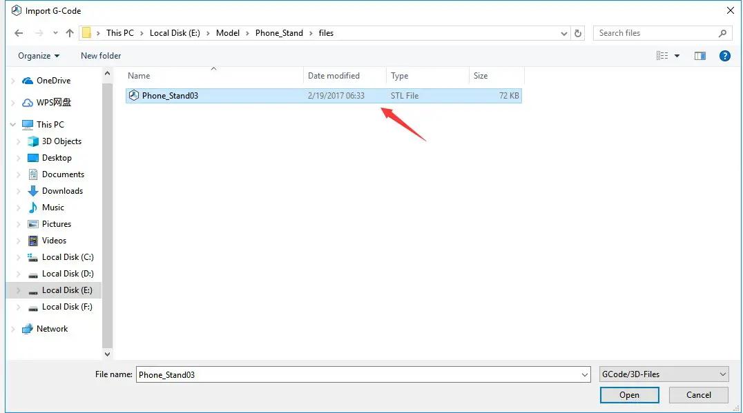
(Picture 8-22)
When it is loaded, you can use the buttons as picture below (picture 8-23) to zoom in, zoom out or rotate the model.
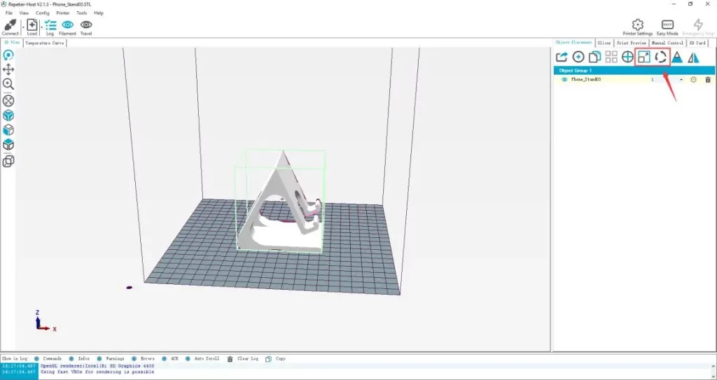
(Picture 8-23)
Adjust the direction of the model so that the flat part of the model is touching the hotbed. See picture below (8-24):
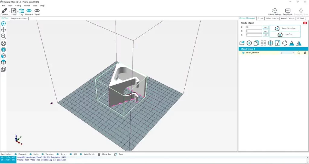
(Picture 8-24)
Note: If the model loaded is too big and beyond the printing platform, you need to zoom out the model. You can perform a uniform scaling. See picture (8-25):
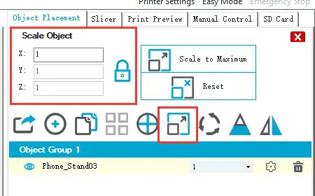
(Picture 8-25)
Or zoom in/out them separately, see picture (8-26).
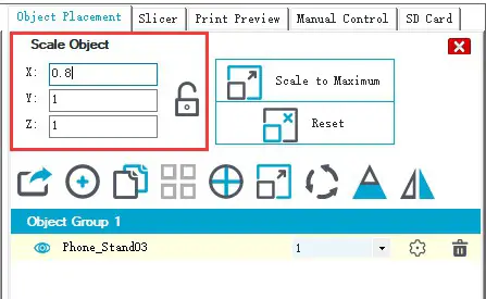
(Picture 8-26)
- Model slicing
When the size and direction of the model are set, choose the imported slicing parameters, and click “Slice with CuraEngine”. See picture (8-27).
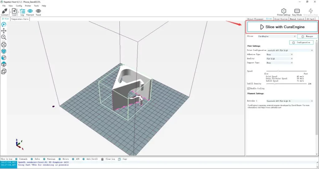
(Picture 8-27)
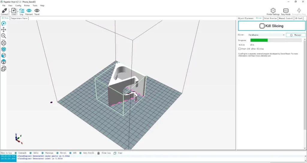
(Picture 8-28)
Waiting for a while after the slice is complete, you can find the model information such as estimated print time, the amount of filament needed, etc. Click “Print” to start USB printing. The printer will heat to the target temp and then start printing. Under high temperature, the filament will flow out of the nozzle, which is normal. You can use tweezers to clean up the residual material of the nozzle.
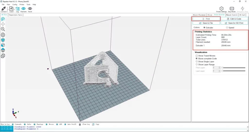
(Picture 8-29)
TF card printing
When all parameters are set, click “Save for SD print”. It will pop up a dialog as picture below (See picture 8-30) and then click the save button to generate a .Gcode file. Copy the Gcode file to the TF card.
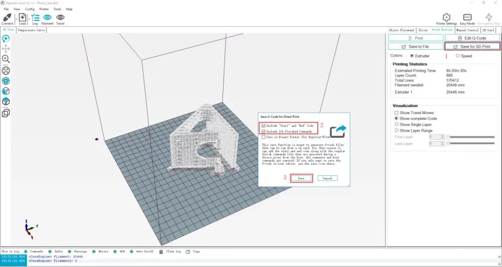
(Picture 8-30)
Insert the TF card into the TF card slot on the front side of the machine. Press the knob to enter the main menu and choose “Print from SD”. See picture (8-31)
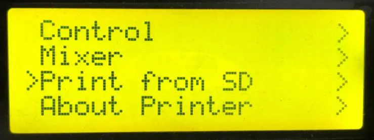
(Picture 8-31)
Choose the corresponding Gcode file to start printing.
Note:
- The printer can only read gcode file and the file name should be English letters, a space, an underscore or their combination.
- The Gcode file cannot be placed in any folder of the TF card, otherwise it cannot be read.
Function introduction
Power loss-resuming capability
In the normal printing process, such as accidental power outage, after the power is restarted, the pop-up prompt option (Power outage), choose “Resume print”. See picture (9-1).

(Picture 9-1)
When it reaches the target temperature, the X and Y axes will auto home. The extruder will extrude the residue in the nozzle. Use a tweezers to clean the nozzle before starting printing again.
Note:
- When power outage, move the nozzle away from the printing model in case the filament oozes out on to the print.
- Be sure to clean the residue in the nozzle before restarting the print or it would affect the quality of the print.
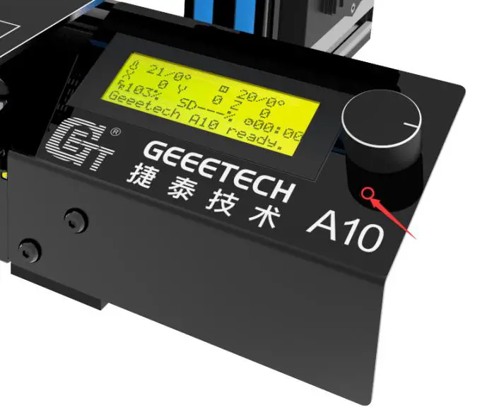
Reset button
The reset button is below the knob. When the printer works abnormally, press the reset button to reset the printer to avoid any damage. See picture (9-2).
(Picture 9-2)
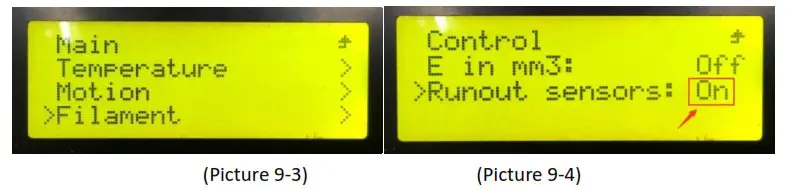
Filament run-out sensor (Optional)
Before using this function, please check whether it is turned on or not. Choose “Control”>”Filament”>“Runout sensors” and after entering the menu, make sure that “Runout sensors” is “On”. See pictures (9-3, 9-4).
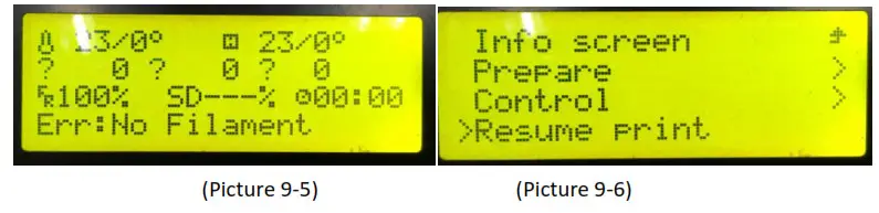
- It will pop up the notification “Err: No Filament” when the filament is run out during printing and the printer will stop. See picture (9-5).
- Press the extruder handle, remove the remaining filament before loading the new filament.
- When the filament is loaded, use a tweezers to clean the nozzle. Press the knob to enter the main menu, and choose “Resume print” to re-start the printing. See picture (9-6).
3D touch for auto bed leveling (Optional)
This printer supports auto bed leveling. Refer to the link below to know how to install the 3d touch sensor.
https://www.youtube.com/watch?v=_RtsZDbR2po&t=66s
Visit our official forum
http://www.geeetech.com/forum/
FAQ (Frequently Asked Questions)
Abnormal extrusion
- The filament is tangled
- The nozzle temp is too low to reach the melting temperature required.
- There is carbonized residue inside the nozzle. Please replace it with the spare nozzle
- Insufficient heat dissipation of radiator of the extruder head causes the filament in the tube to melt in advance and the extrusion strength is insufficient. Please check whether the cooling fan works normally.
- The printing speed is so fast that the extruding speed can’t match it. Please reduce the printing speed.
The gear of the extruder skips and makes an abnormal noise
- The nozzle is clogged; please refer to 10.1 abnormal extrusions.
- Check whether the friction force between the extruder gear and the filament is enough. Please clean the residue.
- Check whether the voltage of the driver of the extruder is normal, and try to increase it by 0.1v until it works normally, max 1.2v.
First layer abnormal
- Non-stick: a. the nozzle is too far from the hot bed. Please re-level the bed, try to
stick masking paper or glue stick on the surface of the hot bed. - Not extruding and the bed scratched: a. the nozzle is too close from the hot bed.
Please re-level the bed; b. check if the nozzle extrusion normal.
Layer shift
- The printing speed is too fast. Please slow it down.
- The belt of X or Y axis is too lose. Please tighten it.
- The X or Y axis synchronization wheel is not fixed firmly. Please adjust the eccentric nuts.
- The voltage of the driver of X/Y axis is too low.
10.5 Print stopped
- USB printing: the signal is interfered. Please copy the model to TF card and print via TF card.
- TF card printing: the gcode file in the TF card is abnormal, please slice again.
- The quality of the TF card is poor. Please try another TF card.
- The power supply voltage in the area is not stable; please print after the voltage is stable.
Visit our official forum for more information: http://www.geeetech.com/forum/viewtopic.php?f=98&t=61864
Declaration
Terms
Please be advised of the following terms (the “Terms”) regarding this User Manual (this “Manual”): All information in this Manual is subject to change at any time without notice and is provided for convenience purposes only. Geeetech reserves the right to modify or revise this Manual in its sole discretion and at any time. You agree to be bound by any modifications and/or revisions. Contact the Geeetech Support Team for up-to-date information.
Disclaimers
Neither Geeetech nor any of our affiliates warrants the accuracy or completeness of the information, products, or services provided by or through this Manual, which are provided “as is” and without any express or implied warranties of any kind, including warranties of merchant ability, fitness for a particular purpose, or non-infringement of intellectual property. To the fullest extent permissible by the applicable law, we hereby disclaim all liability for product defect or failure or for claims that are due to normal wear, product misuse or abuse, product modification, improper product selection, noncompliance with any codes, or misappropriation. To the fullest extent permissible by the applicable law, we hereby disclaim any and all responsibility, risk, liability, and damages arising out of death or personal injury resulting from assembly or operation of our products. Geeetech assumes no responsibility, nor will be liable, for any damages to, or any viruses or malware that may infect your computer, telecommunication equipment, or other property caused by or arising from your downloading of any information or materials related to Geeetech products.
![]() Shenzhen Getech Technology Co.,ltd
Shenzhen Getech Technology Co.,ltd
www.geeetech.com
Geeetech E180 3D Printer
GEEETECH
SAFETY INSTRUCTION
 Do read all the instructions and cautionary markings in this manual before operating your E180 3D printer.
E180 3D printer contains heated moving parts. Never reach the printing head and the building platform while it is in operation or before it has cooled down.
Disconnect your E180 3D printer from the power supply and computer when not in use.
Do not print using materials that have not been approved by GEEETECH for use with the E180 3D printer.
Only operate your E180 3D printer in a well-ventilated space, away from moisture and heat sources with a working smoke/fire alarm.
1
ABOUT E180
Geeetech has launched its brand new cloud 3D printer — E180. Compact and easy-to-manage, E180 is geared toward helping you map your boundless imagination to real experiences and tangible creations through trial and error.
Its classic black and white comparison gives E180 a touch of elegance and simplicity. Made from sheet metal and injection modeling, the whole architecture is endowed with the characteristics of stability, endurance and vibration-resistant performance, hence extraordinary printing experience. The cantilevered design saves much room for enlarging the build volume and enables users to observe the printing in a full view.
E180 features a build volume of 130*130*130mm and runs at a high traveling speed. Adopting Bowden extruder reduces the moving mass of the printing head and allows faster controlled motion, less shaking of E180, and more importantly, faster printing! The extruder extrudes smoothly, avoiding clogging or jamming. Another important feature should be the break-resuming capability, empowering E180 to save and stop the current printing job lest power outage or filament fracture takes place. In a word, it is the rigorous design that enables E180 to deliver smooth surface finish, sleek contour, clear angles and strong structure for the final printout.
Wi-Fi connectivity allows users to enjoy the convenience of cloud 3D printing solution, via which they could make full use of free 3D models, direct real-time control over your printer and share fantastic designs and prints on EasyPrint 3D App. This App is responsive and user-friendly. Besides, E180 comes with a simple and intuitive full-color touch screen which greatly streamlines the whole workflow. On the touch screen, you could use the 5 points leveling method to calibrate the build platform, ensuring great adhesion of the first layer. The leveling method is easy, accurate and effective. Moreover, with a SD card, this color touch screen allows E180 to run untethered to the computer. All these end-to-end user interfaces make the operation flow controllable at your fingertips.
Bearing users’ safety and health in our mind, we designed the hotend of E180 to be entirely enfolded so as to avoid unnecessary scald or danger. In addition, the employment of PLA is environment-friendly, nontoxic and rich in color, fitting E180 perfectly into different circumstances. Furthermore, its simple structure requires low maintenance during the operation process. Only regular lubrication is ok. The modularization of the extruder makes the process of swapping the nozzle a no-brainer, reducing technical hassles. Please download the user manual here:
https://www.geeetech.com/geeetech-e180-mini-3d-printer-p-1017.html
4
5
Accessories
Spare nozzle Filament spool kit


Masking tape Power cable
TF card USB cable
Starter filament Tool kit
6
Specifications
Printing parameters
Print technology: FDM
Build volume: 130x130x130mm
Printing precision: 0.05mm
Positioning precision: X/Y: 0.11mm. Z: 0.0025mm
Print Speed: 80-110mm/s recommended
Filament diameter: 1.75mm
Nozzle diameter: 0.4mm
Filament supported: PLA
Belts:
Operating system: Windows, MAC
Control software: EasyPrint 3D, Cura, Simplify 3D, etc
File format: .stl, G-code
Temperature:
Max extruder temp: About 230°C
Electrical:
Power supply: DC 12V/6A
Connectivity: Wi-Fi, USB, TF card (support stand-alone printing)
Display screen: 3.2 inches Full color touch screen
Mechanical:
Chassis: Metal plate + injection molding
Build Platform: Aluminum alloy plate
XYZ Rods: Wear-resistant, stainless steel and lead screw (Z axis)
Stepper Motors: 1.8°step angle with 1/16 micro-stepping
Physical Dimensions & Weight
Machine dimension: 284x156x320 mm
Shipping box dimension: 374x267x386mm
Machine net weight: 4 kg
Machine gross weight: 6.5kg
8
Contact us
| Technical support | 1. Join our geeetech 3D printer user club.
Here you can get the most professional and just-in-time technical support about your printer. Share anything about your geeetech 3d printer. https://www.facebook.com/groups/315127105604393 2. If you still can not solve problems yourself even with the help of above files, you can send e-mail to [email protected]. |
| Sales | For more products of Geeetech, please visit www.geeetech.com or send e-mail to [email protected] |
| Feedback | In order to improve our products to provide better user experience, please send your comments and suggestions to [email protected]. We will appreciate to hear your valuable suggestions. |
9
GENERAL CARE AND MAINTENANCE
As with all the electronic equipment, it is important to keep your E180 clean to extend its life. Regularly remove dust and debris with a microfiber cloth or compressed air. Dredge the tube and the nozzle after use every time to ensure fluent performance.
- Don’t leave the heaters on the printer turned on for a long
periods of time when not used. - Don’t leave your printer in shady and moist places, which may exacerbate the problems associated with erosion.
- The three axes of the E180 are lubricated with grease for smooth operation and can last for a long time. Grease may need to be re-applied to your printer to maintain smooth performance.
- Avoid positioning your power supply unit in such a way that the brick is hanging, pulling, or putting any unnecessary stress in the electrical wires and components.
10

Geeetech Rostock 301 3D printer
Assembly Manual
GEEETECH
SUPPROT
Thanks for choosing Geeetech, we strive to provide a satisfied and pleasant shopping experience for you, but we do understand there may be some questions you may encounter in using our product. If so, you can contact us directly or post on our forum, our technique staff will help you resolve it. For more detailed information, please visit Geeetech website.
For detailed building videos, please check at YouTube:
https://goo.gl/adghBa
Subscribe our YouTube channel for more videos.
https://www.youtube.com/user/geeetech
Join our geeetech 3D printer user club.
https://goo.gl/GhJbe3
Feel free to drop a line at [email protected] .
– 1 –
GEEETECH
INTRODUCTION:
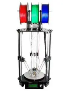
Geeetech Rostock 301 is an affordable desktop 3D printer for tech enthusiasts, serious hobbyists and educators. This printer provides you with excellent printability and triple-color, mix color capability, offering an intuitive 3D printing experience.
Rostock 301 is a perfect combination of the delta type construction and the 3-in-1-out mix color 3D printing hotend. Delta type construction features faster printing speed and high printing accuracy; the 3-in-1-out mix color 3D printing hotend gives a rich mixture of color combination of the printing object.
Rostock 301 maintains DIY property, with which you can unleash your creativity to refit or modify it as you like. This kit is just the beginning; you can get more out of it.
– 2 –
GEEETECH
PACKAGE LIST:
This list includes all the parts required to assemble your Rostock 301 3D Printer. After you received your package, please check if all the parts listed are included. Also make sure all the components are in good condition and not damaged during shipping. If anything is missing please contact with our customer service straight away, provide us the NO. , Name, and Qty.
| Mechanical parts | ||||
| No | Name | Specifications | Qty | Pic |
| 1 | Smooth Rod |
ф10 L500mm (±2mm) |
6 |  |
| 2 | Filament Spool |
ф8 L318mm (±2mm) |
1 |  |
| 3 | Rod-end bearing holder |
ф6.5 20mm |
12 |  |
– 3 –
GEEETECH
| 4 | Diagonal Rod |
With rod-end bearing |
6 |  |
| 5 | M3 Washers |
M3 | 125 |  |
| 6 | M4 Washers |
M4 | 30 | |
| 7 | M8 Washers |
M8 | 15 | |
| 8 | Nut | M2.5 | 8 |  |
| 9 | Nut | M3 | 15 | |
| 10 | Nut | M5 | 25 |  |
| 11 | Lock nut |
M4 | 5 |  |
– 4 –
GEEETECH
| 12 | Wing nut | M3 | 8 |  |
| 13 | Square nut | M3 | 35 |  |
| 14 | Hex sunk screw |
M3x12 mm | 5 |  |
| 15 | Hex sunk screw |
M3x30 mm | 5 | |
| 16 | Round head screw with pad |
M3 x 8 mm | 15 |  |
| 17 | Screw | M2.5x16mm | 8 |  |
| 18 | Screw | M3x5mm | 15 | |
| 19 | Screw | M3x8mm | 20 | |
| 20 | Screw | M3x12mm | 40 | |
| 21 | Screw | M3x16mm | 40 | |
| 22 | Screw | M3x20mm | 10 |
– 5 –
GEEETECH
| 23 | Screw | M3x25mm | 8 | |
| 24 | Screw | M3x40mm | 5 | |
| 25 | Screw | M4x8mm | 15 |  |
| 26 | Screw | M4x12mm | 15 | |
| 27 | Screw | M4x20mm | 5 | |
| 28 | Screw | M5x16 | 15 |  |
| 29 | Screw | M5x20 | 15 | |
| 30 | Spring | 4.0x 20 (for heat bed) |
5 |  |
| 31 | Spring | 3.5*30 (for endstop trigger) |
5 |  |
| 32 | locking ring |
M8 With Jimmy bolt |
4 |  |
| 33 | Ball Bearing |
MR84zz (Placed in No.34) |
6 |  |
– 6 –
GEEETECH
| 34 | Driven wheel |
3 |  |
|
| 35 | Driven wheel holder |
Sheet metal part |
3 |  |
| 36 | Pulley | 20 tooth | 3 |  |
| 37 | Linear Bearing |
PCS10UU | 6 |  |
| 38 | Timing Belts |
2GT L= 1200mm |
3 |  |
| 39 | Spacer | With Aircraft type end |
8 |
– 7 –
GEEETECH
| 40 | Nylon ties | 20 |  |
|
| 41 | bowden tubes |
PTFE L=600mm | 3 |  |
| 42 | Spiral Coil | 1 meter | 1 |  |
| 43 | Sticker | 2 |  |
|
| 44 | Heat sink | 9*10*5mm | 6 |  |
| 45 | Cable Clip | 1 |  |
|
| 46 | Hex copper spacer |
6 |
– 8 –
GEEETECH
| 47 | End stop | Blue–1pcs Red– 1pcs Black–1pcs |
1 |  |
| 48 | Fan | 40x40x10mm | 1 |  |
| 49 | Extensio n wire |
3Pin Male-3Pin Female |
1 |  |
| 50 | 3-1 motor wire |
For X/Y/Z motors |
1 |  |
| 51 | Extruder Motor wire |
6-4pin | 3 |  |
– 9 –
GEEETECH
| 52 | Extruder wire | 3 |  |
|
| 53 | Knob | For LCD control | 1 |  |
| 54 | LCD kit | LCD2004+ FPC Ribbon cable |
1 |  |
| 55 | Control board kit |
GTM32 pro + 6 A4988 |
1 set |  |
| 56 | Heatbed set |
with Heating wire + Thermistor wire |
1 |  |
– 10 –
GEEETECH
| 57 | Stepper motor |
For X/Y/Z axis | 3 |  |
| 58 | Extruder | 3 | 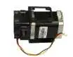 |
|
| 59 | Extensio n board |
3 | 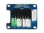 |
|
| 60 | Hotend | 3-in-1-out hotend | 1 |  |
– 11 –
GEEETECH
| 61 | Power Supply Unit |
12V/20A | 1 |  |
| 62 | 3D printer Power Cable |
With plug | 1 | 
|
| 63 | Power Cable | Connect board to PSU | 1 |  |
| 64 | USB cord | A-BA | 1 |  |
| Acrylic parts | ||||

– 12 –
GEEETECH
| A1 | Top plate | RK-01 | 1 |  |
| A2 | Base plate | RK-02 | 1 |  |
| A3 | Motor holder | RK-03 | 3 |  |
| A4 | Motor holder support | RK-04 | 6 |  |
| A5 | Drive wheel mount | RK-05 | 3 |  |
| A6 | Endstop mount |
RK-06 | 3 |  |
– 13 –
GEEETECH
| A7 | Fan mount | RK-07 | 1 |  |
| A8 | LCD frame | RK-08 | 1 | 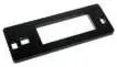 |
| A9 | LCD support | RK-09 5mm | 2 |  |
| A10 | Spool holder Side panel | RK-10 | 1 |  |
| A11 | Spool holder Side panel | RK-11 | 1 |  |
| A12 | Carriage mount |
RK-12 | 3 | 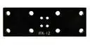 |
– 14 –
GEEETECH
| A13 | PSU case part1 |
1 |  |
|
| A14 | PSU case part2 |
2 |  |
|
| A15 | PSU case part3 |
1 |  |
|
| A16 | PSU case part4 |
1 |  |
|
| metal parts | ||||
| M1 | Spider | 1 |  |
|
– 15 –
GEEETECH
| M2 | Belt mount | 3 |  |
|
| M3 | Endstop trigger mount |
3 |  |
|
| M4 | Diagonal Rod joint |
6 |  |
|
| M5 | Building platform |
Round aluminum plate |
1 |  |
| M6 | Extension board cover |
3 |  |
|
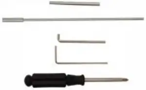
| Free add-on | ||||
| F1 | Ejector pin | 1 |  |
|
– 16 –
GEEETECH
| F2 | File | 1 |  |
|
| F3 | Screw-driver | 1 |  |
|
| F4 | Starter filament |
3 meters Random color | 1 |  |
– 17 –
GEEETECH
GENERAL CARE AND MAINTENANCE
As with all the electronic equipment, it is important to keep your printer clean to extend its life. Regularly remove dust and debris with a microfiber cloth or compressed air. Dredge the tube and the nozzle after use every time to ensure fluent performance.
- Don’t leave the heaters on the printer turned on for a long periods of time when not used.
- Don’t leave your printer in shady and moist places, which may exacerbate the problems associated with erosion.
- Lubricated the linear bearings on the three axes with grease to avoid oxidation for smooth operation.
- Avoid positioning your power supply unit in such a way that the brick is hanging, pulling, or putting any unnecessary stress in the electrical wires and components.
– 18 –
![]()
GEEETECH
]]>