FORTINET FortiGate 200F Series Enterprise-Grade Protection for Smaller Networks

Introduction
Purpose and Scope
MerryIoT Hotspot Miner V1 is designed for edge computing applications in IoT, Smart Manufacturing, Automation, Blockchain and etc, to support high performance, high reliability and high throughput for the heavy data processing demand.
MerryIoT Hotspot Miner V1 is targeting at AIoT applications with quad A55 cores, G52 GPU hardware, based on Linux distribution. IoT solution providers can easily integrate advanced and stable functions for their application-centric development on their own IoT projects.
Product Design
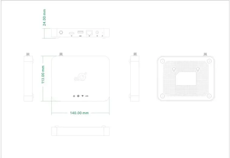
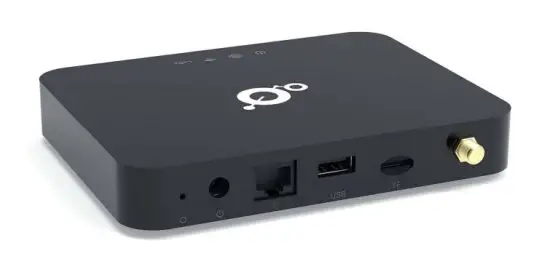
The dimension of L0001 Helium Hotspot Miner V1 is with the dimension of 140 x 110 x 24 mm, and with one LAN port, one USB port, One TF card and 12V1A power input, four LED indicators, and one reset button.
Product Features
- Up to 8 concurrent channels for LoRa transmission
- Built-in 2.4G 802.11b/g/n Wireless LAN, and Bluetooth 5.2
- Various Internet connections: Ethernet, WiFi
- Support LoRaWan 1.0.3 packet forwarder and Basic Station mode
- Ethernet/WiFi Configuration through APP
- Support BROWN OTA
- External antennas for LoRa and internal antenna for WiFi connection
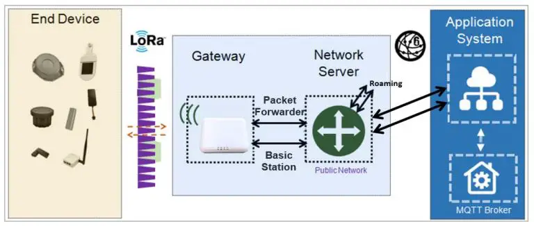
System Architecture
Definitions, Acronyms and Abbreviations
| Item | Description |
| LPWAN | Low-Power Wide-Area Network |
|
LoRaWAN™ |
LoRaWAN™ is a Low Power Wide Area Network (LPWAN) specification intended for wireless battery-operated Things in a regional, national or global network. |
| ABP | Activation by Personalization |
| OTAA | Over-The-Air Activation |
| TBD | To Be Defined |
Reference
| Document | Author |
| LoRaWAN Specification v1.0.3 | LoRa Alliance |
| RP002-1.0.1 LoRaWAN Regional Parameters | LoRa Alliance |
| LoRaWAN Backend Interfaces Specification v1.0 | LoRa Alliance |
Hardware Details
LED Indicators
LED sequence: Power(System), Internet,WiFi, LoRa,BT.
Four Green, One White Solid LED is for static status, blanking means system is upgrading or active devices linked to the corresponding port
| Solid On | Blinking | Off | |
| Power System(Green) | Power ON | Booting/OTA | Power Off |
| Internet(Green) | Internet available | Check Internet | RFU |
| Wireless(Green) | Wireless connected to root AP | RFU | Wireless NOT connected to root AP |
| LoRa(Green) | LoRa is working | Initialing | LoRa is not working |
| BT(White) | BT Advertising | BT Button pressed | No BT Advertising |
I/O Ports
| Port | Coun t | Description |
| RJ45 | 1 | WAN port of the device |
| Reset | 1 | Reset to default (5 seconds to reset settings to factory default) |
| USB | 1 | Power input via USB adaptor(5VDC/2A) |
| TF Card |
Back Label
The marking information is located at the bottom of apparatus.
Package Label
| N
o. |
Item | Description |
| 1 | Product BOX | Gift Box |
| 2 | Labeling | Model/ MAC/ Serial Number/ Type Approval |
Package Content
| N
o. |
Item | Description |
| 1 | Product BOX | Gift Box |
| 2 | Labeling | Model/ MAC/ Serial Number/ Type Approval |
| 1 | MerryIoT Hotspot Miner V1 | 1 |
| 2 | Power adapter (12V/1A) | 1 |
| 3 | LoRa Antenna and Base | 1 |
System Specification
Hardware Specification
| No. | Item | Description |
| 1 | CPU | – Rockchip RK3566
– Quad-core Cortex-A55 up to 1.8GHz |
| 2 | Memory | – DDR3/4 4GB |
| 3 | Storage | – eMMC 32GB |
| 4 | LoRa radio | – US 915 SKU
– External SMA antenna |
| 5 | W-Fi radio | – 2.4GHz 1Tx/1Rx 802.11 b/g/n
– Built-in antenna |
| 6 | BLE radio | – 2.4GHz BLE 5.2
– Built-in antenna |
| 7 | Crypto chip | – I2C control
– Microchip ATECC608A/B in SOIC-8 and UDFN-8 |
| 8 | LAN interface | – RJ45 1Gbps x 1 |
| 9 | TF | – External TF card slot
– Supports SDXC or higher speed |
| 10 | USB | – External USB-A 2.0 connector
– Reserved for future use |
| 11 | LEDs | – Logo
– Single colored LED indicator (green) x 4 n Power n Status n System n Wi-Fi |
| 12 | Button | – Push button (GPIO) |
| 13 | Console | – Debug UART console |
| 14 | Environment | – Temp. operating -10°C ~ +40°C ambient
– Storage -20°C ~ +70°C ambient – Humidity operating 5%RH ~ 95%RH (non-condensed relative humidity) – Altitude operating 0 ~ 3000 Meters |
| 15 | IP ratings | – IP42 (plastic enclosure) |
| 16 | Size | – 140x110x20 mm |
| 17 | Power | – DC jack
– DC12V 1~1.5A |
| Note | ||
LoRa Specification
| No. | Item | Description |
| 1 | Channels | 125K: 922.0MHz~924.6MHz 250K: 921.8MHz~924.5MHz FSK:921.8MHz~924.8MHz |
| 2 | Chipset | SX1302+SX1250 (x2) |
| 3 | Bandwidth | 125KHz/ 250KHz |
| 4 | Power | 5VDC, 500mA (typical) |
| 5 | Antenna | 1 ipex connector on board for external antenna |
| 6 | Interface | SPI for data communication |
| 7 | GPIOs | To control SX1262 (chip select) |
| 8 | Form Factor | – Mini-PCIe
– 40 x 50 (w/golden pins) x 3 mm |
| 9 | Channel Plan
-US923 |
– Uplink
Frequency (MHZ) Frequency (MHZ) Spreading Factor n 923.2 – SF7BW125 to SF12BW125 n 923.4 – SF7BW125 to SF12BW125 n 922.2 – SF7BW125 to SF12BW125 n 922.4 – SF7BW125 to SF12BW125 n 922.6 – SF7BW125 to SF12BW125 n 922.8 – SF7BW125 to SF12BW125 n 923.0 – SF7BW125 to SF12BW125 n 922.0 – SF7BW125 to SF12BW125 n 922.1 – SF7BW250 n 921.8 – FSK – -Downstream Frequency (MHZ) Spreading Factor n Uplink channels 1-10 (RX1) n 923.2 – SF10BW125 (RX2) Downlink Frequency (MHZ) – Upstream Frequency (MHZ) Spreading Factor n 923.2 – SF7BW125 to SF12BW125 n 923.4 – SF7BW125 to SF12BW125 n 923.6 – SF7BW125 to SF12BW125 n 923.8 – SF7BW125 to SF12BW125 n 924.0 – SF7BW125 to SF12BW125 n 924.2 – SF7BW125 to SF12BW125 n 924.4 – SF7BW125 to SF12BW125 n 924.6 – SF7BW125 to SF12BW125 n 924.5 – SF7BW250 n 924.8 – FSK – – Downstream Frequency (MHZ) Spreading Factor n Uplink channels 1-10 (RX1) n 923.2 – SF10BW125 (RX2) |
| Note: LoRa frequency is user defined. | ||
Software Specification
Configuration/Performance/Capability
| Req. # | Features | Description | comment |
| PR- 0001 | Network Configuration |
· WiFi or Ethernet switch Configuration |
|
| PR- 0002 |
BLE Name |
MerryIoT Hotspot V1_xxxxxx where the last hex are the last 6 uppercase hex of the MAC address. |
|
PR- 0003 |
OTA |
· OTA daily check
· Browan OTA · ALi OTA · 同時更新 loading 的問題? |
|
|
PR- 0003 |
SSH Password |
Account : root
Password: Create by MerryIot sign key based on MAC · 8 characters · English uppercase and lowercase, 2~9 numbers ( default Skip: 0,O,1,I,l, o ) |
|
|
PR- 0004 |
Gateway Config |
· Network setting WiFi
o App 不能 skip WiFi · 設定 Helium on boarding |
Basic Features
| Req. # | Features | Description | comment |
| PR-1001 | BLE Button | · Over 6 seconds then trigger BLE provision | |
|
PR-1002 |
LED |
· 5 LEDS
o Power LED o Internet LED o WiFi LED o LoRa LED o BT LED · Refer to Table 1 LED Behavior. |
|
| PR-1003 | Ethernet | · Ethernet connection | |
| PR-1004 | WiFi Station | · WiFi Station Mode | |
| PR-1005 | BLE | · Configuration through BLE | |
|
PR-1006 |
Debug port |
· UART for debug |
|
|
PR-1007 |
OTA |
· OTA agent |
|
|
PR-1008 |
SW Monitor |
· Monitor packet forwarder
· Monitor Helium Miner · Monitor Gateway Config |
|
| PR-1009 | HW Watchdog | · Monitor system |
LoRaWAN features
| Req. # | Features | Description | comment |
| PR- 2001 | Packet Forwarder | · Compatible with Semtech LoRa Packet Forwarder | |
| PR- 2002 | Miner Application |
· Miner Application |
|
| PR- 2003 |
gateway_mfr |
· Swarm key provision |
|
| PR- 2004 |
Gateway config |
· WiFi Setting
· Helium on boarding |
Regulatory Specification
| No
. |
Item | Standard |
| 1 | FCC/IC | TBD |
| 2 | NCC | TBD |
| EN 300 328 V2.2.2(included EN 62311/EN 50665/EN 50385) | ||
| EN 300 220-2 V3.1.1 | ||
| EN 301 489-1 V2.2.3 | ||
| 3 | CE | EN 301 489-3 V2.1.1 |
| EN 301 489-17 V3.2.4 | ||
| EN 55032 / EN 55024 | ||
| EN 62368-1 LVD | ||
| 4 | RCM | TBD |
Reliability Specification
| No. | Item | Specification |
| 1 | MTBF | 300,000 @ 40 C |
User Manual
Connect MerryIoT Hotspot
You can connect to the gateway via the WiFi interface which the SSID and password printed on the back label by default.
The rule of gateway SSID is MerryIoT-xxxxxx where the last digits are the last 6 digits of the MAC address. The PC will fetch IP address of range 192.168.4.x except 192.168.4.1 assigned by the AP.
Hotspot Setting
Open the web browser(ex: Chrome) after connecting to the gateway via IP address“192.168.4.1”
Now you can configure the gateway through the WEB UI.
SET WAN
The gateway support either “Ethernet” or “Wi-Fi” connection as the internet backhaul.
Ethernet Setting
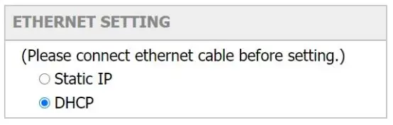
Configure the IP address of WAN.[Static IP/DHCP client]
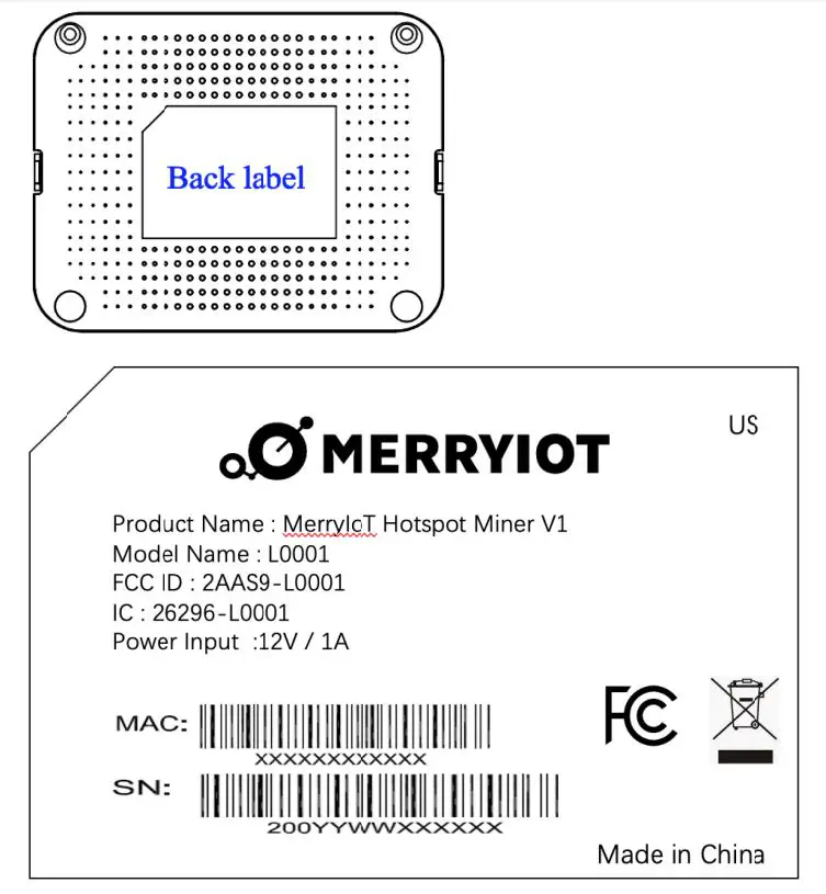
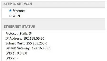
Figure 5 – WAN connection
ETHERNET STATUS – The information of IP address/Subnet Mask/Gateway/DNS.
ETHERNET SETTING – Configure the IP address of WAN.[Static IP/DHCP client]
Static IP – Setup the IP address/Subnet Mask/Default Gateway/DNS of the static IP.
DHCP – The IP address/Subnet Mask/Default Gateway/DNS will be assigned by the DHCP server.
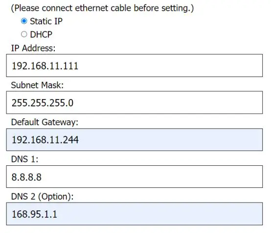
Figure 6 –DHCP client
STEP 1Wi-Fi
Select “Wi-Fi” to be the internet backhaul connection.
The gateway WiFi interface is the Access Point by default which SSID is “Femto_Lite-XXXXXX” printed on the back label. Administrator can only access to the WEB UI through the Access Point mode to configure the gateway. The gateway will be the WiFi client and won’t access to the WEB UI after enable WiFi interface as the internet backhaul connection.
MANUAL CONNECT–Specify the remote AP SSID and enter the password if necessary.
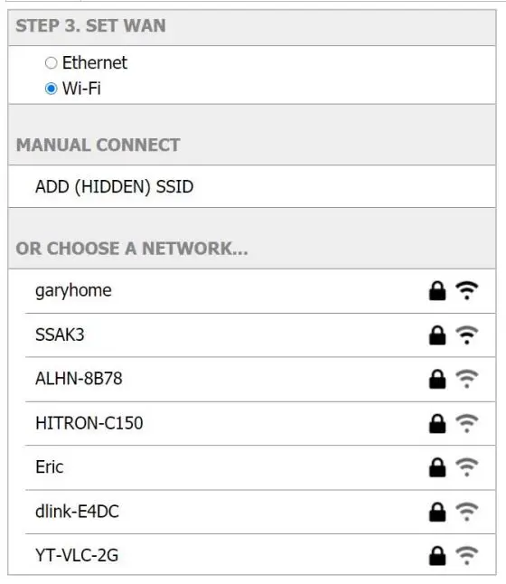 Figure 8 – Wi-Fi manual connection
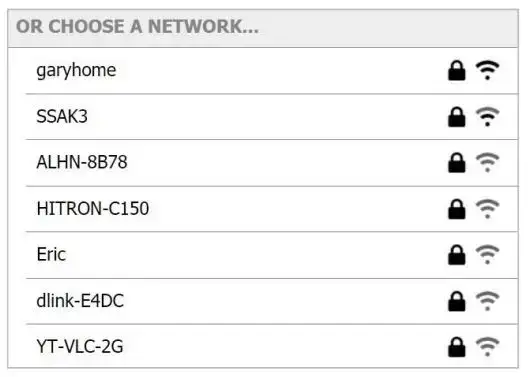
The gateway will scan the neighbor access point automatically. Just click the SSID for the WiFi connection.
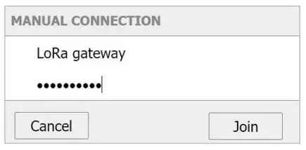
Enter WiFi password if it is necessary for the connection.
Federal Communication Commission Interference Statement
This equipment has been tested and found to comply with the limits for a Class B digital device, pursuant to Part 15 of the FCC Rules. These limits are designed to provide reasonable protection against harmful interference in a residential installation. This equipment generates, uses and can radiate radio frequency energy and, if not installed and used in accordance with the instructions, may cause harmful interference to radio communications. However, there is no guarantee that interference will not occur in a particular installation. If this equipment does cause harmful interference to radio or television reception, which can be determined by turning the equipment off and on, the user is encouraged to try to correct the interference by one of the following measures:
- Reorient or relocate the receiving antenna.
- Increase the separation between the equipment and receiver.
- Connect the equipment into an outlet on a circuit different from thatto which the receiver is connected.
- Consult the dealer or an experienced radio/TV technician for help.
FCC Caution: Any changes or modifications not expressly approved by the party responsible for compliance could void the user’s authority to operate this equipment.
This device complies with Part 15 of the FCC Rules. Operation is subject to the following two conditions:
- This device may not cause harmful interference, and
- this device must accept any interference received, including interference that may cause undesired operation.
IMPORTANT NOTE:
Radiation ExposureStatement:
This equipment complies with FCC radiation exposure limits set forth for an uncontrolled environment. This equipment should be installed and operated with minimum distance 20cm between the radiator & your body. This transmitter must not be co-located or operating in conjunction with any other antenna or transmitter. Country Code selection feature to be disabled for products marketed to the US/CANADA Operation of this device is restricted to indoor use only
Industry Canada statement:
This device contains license-exempt transmitter(s)/receiver(s) that comply with Innovation, Science and EconomicDevelopmentCanada’s license-exempt RSS(s). Operation is subject to the following two conditions:
- This device may not cause interference
- This device must accept any interference, includinginterferencethatmay cause undesired operation of the device
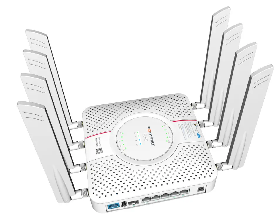
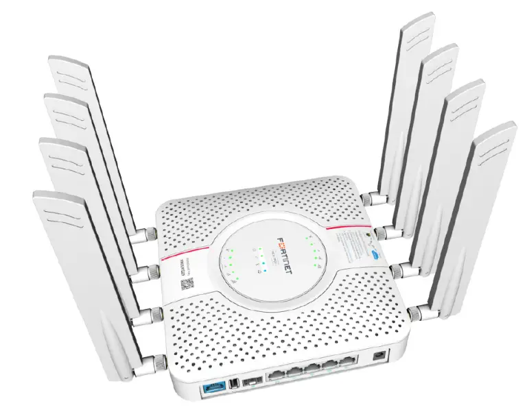
FORTINET FortiExtender 311F 3G/4G LTE Wireless WAN Extenders

Copyright © 2021 Fortinet, Inc. All rights reserved. Fortinet®, FortiGate®, FortiCare® and FortiGuard®, and certain other marks are registered trademarks of Fortinet, Inc., in the U.S. and other jurisdictions, and other Fortinet names herein may also be registered and/or common law trademarks of Fortinet. All other product or company names may be trademarks of their respective owners. Performance and other metrics contained herein were attained in internal lab tests under ideal conditions, and actual performance and other results may vary. Network variables, different network environments and other conditions may affect performance results. Nothing herein represents any binding commitment by Fortinet, and Fortinet disclaims all warranties, whether express or implied, except to the extent Fortinet enters a binding written contract, signed by Fortinet’s General Counsel, with a purchaser that expressly warrants that the identified product will perform according to certain expressly-identified performance metrics and, in such event, only the specific performance metrics expressly identified in such binding written contract shall be binding on Fortinet. For absolute clarity, any such warranty will be limited to performance in the same ideal conditions as in Fortinet’s internal lab tests. In no event does Fortinet make any commitment related to future deliverables, features or development, and circumstances may change such that any forward-looking statements herein are not accurate. Fortinet disclaims in full any covenants, representations, and guarantees pursuant hereto, whether express or implied. Fortinet reserves the right to change, modify, transfer, or otherwise revise this publication without notice, and the most current version of the publication shall be applicable.
Register for Support
Register your Fortinet product to receive:
- Technical Support
- New product features
- Protection from new threats
https://support.fortinet.com
Toll-free: 1 866 648 4638
Phone: 1 408 486 7899
Fax: 1 408 235 7737
Email: [email protected]
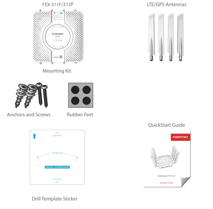
Packing List
Product Description
All FEX-311F and 312F products feature the same FEX-300F chassis with one (1) or two (2) CAT16 LTE modules pre-installed, as highlighted below.
Product Features
| Model | Modem |
| FEX-311F | FEX-300F chassis with one (1) CAT16 LTE module pre-installed. |
| FEX-312F | FEX-300F chassis with two (2) CAT16 LTE modules pre-installed. |
Notes:
- CAT16 LTE modules (downlink: maximum 1 Gbps; uplink: maximum 150 Mbps)
- FEX-311F and 312F only support MicroSIM (3FF) SIM cards, which are not included. You must purchase your own SIM cards.
Ports, LEDs, and Buttons
LED Behavior
| LED | Behavior and Description |
| SFP |
|
| WAN/LAN LEDs |
|
| Bluetooth LED |
|
Control Button Usage
| Button | Operating Instructions |
| Reset/Default Button |
|
| Bluetooth Button |
|
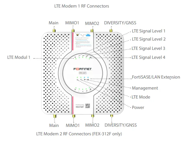
RF Connectors & System LEDs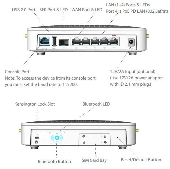
Note:
- The upper LTE LEDs are for LTE Modem 1; the lower LEDs are reserved for LTE Modem 2.
- The LTE LEDs apply to both Modems 1 and 2.
- The Management and FortiSASE/LAN Extension LEDs apply to both FEX-311F and FEX-312F models.
System LEDs on top of the FEX-311F/312F
| LED | Description |
| Power |
|
| LTE Mode | Green—System is running in LTE mode. |
| Management |
|
| FortiSASE/LAN Extension |
|
| Bluetooth |
|
| LTE LEDs | Description |
| LTE |
|
| LTE Signal Strength | 1 On—< 25%. |
| LEDs | 1 & 2 On—25% – 50%. |
| (Green) | 1, 2 & 3 On—50% – 75%. |
| 1, 2, 3, & 4 On—> 75%. |
Note: The above decriptions apply to both Modem 1 and Modem 2. Modem 2 applies to FEX 312F only.
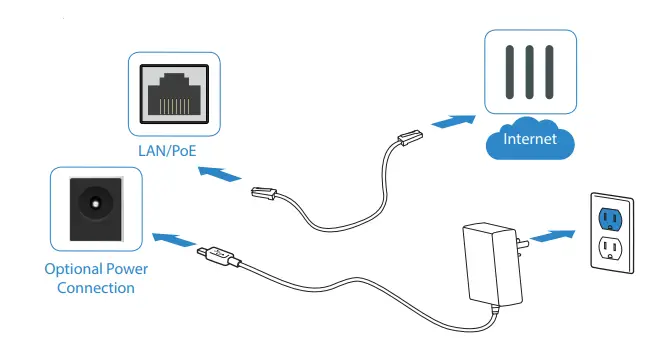
Basic Connections
- Insert one end of an Ethernet cable into the LAN/PoE port on the device.
- Insert the other end of the Ethernet cable into the PoE LAN port on your FortiGate appliance. Ensure that FortiGate and FortiExtender are on the same subnet.
- Optionally, if you are not using PoE, connect the device to a power outlet using a power adapter.
Warning:
You must provide adequate grounding to the PoE injector of the FortiExtender unit, if required, in compliance with your local electrical code or regulations. This device complies with IEEE 802.3af/at PoE specification. Do not use a PoE injector that is not IEEE 802.3af/at compliant as it might damage your device.
Assembly
- Remove the dust cover that protects the SIM sockets and fits over the antenna posts.
- Insert your MicroSIM (3FF) SIM card(s) into the SIM socket(s).
- Observe the following guidelines:
- If installing one SIM card, you can insert the card into either SIM socket.
- If installing two SIM cards, use SIM1 as the primary socket and SIM2 as the secondary.
- Insert the SIM card(s) into the SIM socket(s), making sure that the card is facing down with the cut corner on the right. (If necessary, press the card again to remove it.)
- Replace the cover, and then attach the antennas.
IP Configuration
After you have connected the FortiExtender network interfaces, the device automatically attempts to obtain an IP address from a DHCP server. If you do not use DHCP, you can configure a static IP address.
To configure a static IP address:
- Use an Ethernet cable to connect one of the LAN ports in the back of the
FortiExtender to the Ethernet port of your computer. - Set the computer Ethernet port to DHCP mode, and connect it to port1, port2, or port3.
- Open your web browser and point to the default FortiExtender web GUI address: http://192.168.200.99
- In both the username and password fields, type admin and press the Enter key on your keyboard.
- Go to Networking>Interface, where you’ll see all the system interfaces.
- Select a desired interface, set it to “static” mode, configure the static IP address, and click Save.
Installation
The FortiExtender device is designed for placement near a window (desk or wall mount) to achieve the best LTE signal strength. Refer to the diagram below for proper placement and mounting.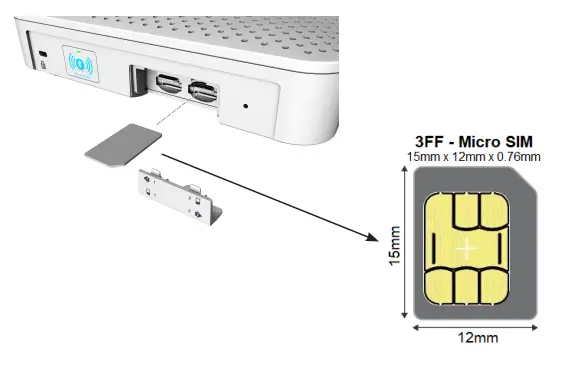
Install SIM card(s)
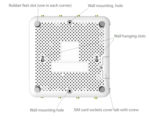
- Unscrew the SIM card sockets cover on the bottom of the unit.
- Push the screw tab outwards, and unlock the cover from one end to remove it.
- Insert your MicroSIM (3FF) SIM card(s) into the SIM socket(s).
- Replace the SIM card sockets cover, and fasten it onto the unit housing with the screw.
Place on top of a desk or flat surface
- Attach the rubber feet to the four corners on the bottom of the unit.
- Place the unit on the desk or flat surface.
- Secure the unit in place with a Kensington lock.
- Attach the antennas.
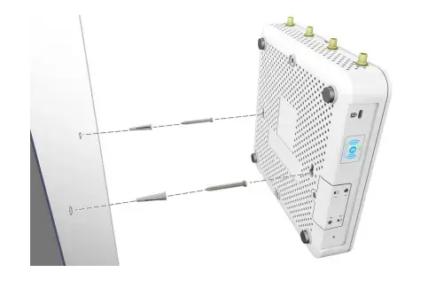
Hang on a wall
- Peel off the drill template sticker, and stick it onto the wall in a desired location.
- Use the template to mark and drill the pilot holes.
- Insert the anchors into the holes.
- Insert the screws into the anchors and tighten, leaving around a 5-mm gap between the screw head and the wall.
- Position the device so that the mounting holes line up with the screws.
- Place the mounting slots over the screws and slide the device down until the screws fit into the slots.
Tip: Use bear claw screws. The screw heads of bear claw screws have a built-in gap that fits well with the hanging holes. You can purchase bear claw screws from a local or online hardware store.
Fasten onto a wall
- Peel off the drill template sticker, and stick it onto the wall in a desired location.
- Use the template to mark and drill the pilot holes.
- Insert the anchors into the holes.
- Snap off the plastic cover over the LEDs on the front to reveal the long screw holes.
- Insert the long screws through the device from front to back.
- Insert the long screws into the anchors on the wall and tighten.
- Replace the cosmetic cover over the LEDs on the front. Refer to the illustrations on the next page.
Cautions and Warnings
Environmental specifications
Ambient operating temperature: 0°C to 40°C
Refer to specific Product Model Data Sheet for Environmental Specifications (Operating Temperature, Storage Temperature, Humidity, and Altitude)
Référez à la Fiche Technique de ce produit pour les caractéristiques environnementales (Température de fonctionnement, température de stockage, humidité et l’altitude).
Safety
Caution: This equipment is to be used in a Network Environment 0 per IECTR 62101. This product is connected only to PoE networks without routing to the outside plant.
This product is intended to be supplied by a Listed Direct Plug-In Power Unit marked LPS or Class 2 and rated 12 Vdc, 2 A or by 54 Vdc from PoE source. Le produit doit être alimenté par un bloc d’alimentation à courant continu homologué UL de 12 Vdc, 2 A nominal marqué LPS ou Class 2 ou par une source d’alimentation par Ethernet de 54 Vdc (PoE).
Regulatory Notices
Federal Communication Commission (FCC) – USA
This device complies with Part 15 of FCC Rules. Operation is subject to the following two conditions:
- This device may not cause harmful interference, and
- This device must accept any interference received; including interference that may cause undesired operation.
This equipment has been tested and found to comply with the limits for a Class B digital device, pursuant to Part 15 of the FCC Rules. These limits are designed to provide reasonable protection against harmful interference in a residential installation. This equipment generates, uses, and can radiate radio frequency energy, and if it is not installed and used in accordance with the instruction manual, it may cause harmful interference to radio communications. However, there is no guarantee that interference will not occur in a particular installation.
If this equipment does cause harmful interference to radio or television reception, which can be determined by turning the equipment off and on, the user is encouraged to try to correct the interference by one or more of the following measures:
- Reorient or relocate the receiving antenna.
- Increase the separation between the equipment and receiver.
- Connect the equipment into an outlet on a circuit different from that to which the receiver is connected.
- Consult the dealer or an experienced radio/TV technician for help.
WARNING: Any changes or modifications to this unit not expressly approved by the party responsible for compliance could void the user’s authority to operate the equipment.
This equipment complies with FCC radiation exposure limits set forth for an uncontrolled environment. This equipment should be installed and operated with minimum distance 20cm between the radiator and your body. This transmitter must not be co-located or operating in conjunction with any other antenna or transmitter.
Industry Canada Equipment Standard for Digital Equipment (ICES) – Canada
This Class B digital apparatus complies with Canadian ICES-003.
Cet appareil numérique de la classe B est conforme à la norme NMB-003 du Canada.
Innovation, Science and Economic Development (ISED) – Canada
This device contains licence-exempt transmitter(s)/receiver(s) that comply with Innovation, Science and Economic Development Canada’s licence-exempt RSS(s). Operation is subject to the following two conditions:
- This device may not cause interference.
- This device must accept any interference, including interference that may cause undesired operation of the device.
This equipment complies with ISED radiation exposure limits set forth for an uncontrolled environment. This equipment should be installed and operated with minimum distance 20cm between the radiator & your body.his radio transmitter (IC: 7280B-111M01A / Model: FEX-311F, FEX-312F) has been approved by ISED to operate with the antenna types listed below with the maximum permissible gain and required antenna impedance for each antenna type indicated. Antenna types not included in this list, having a gain greater than the maximum gain indicated for that type, are strictly prohibited for use with this device.
| Antenna Type | Connector | Antenna Gain (dBi) | Remark |
| Dipole External Antenna | SMA | 1559 MHz—1606 MHz: 0.92 | GPS |
| Chip | N/A | 2400 MHz—2483.5 MHz: 1.08 | Bluetooth |
| Dipole External Antenna | SMA | 617 MHz—798 MHz: 0.8 824 MHz—960 MHz: 1.91 1452 MHz—1606 MHz: 0.92 1710 MHz—2690 MHz: 2.4 3300 MHz—4200 MHz: 3.28 5150 MHz—5925 MHz: 4.8 |
WWAN |
European Conformity (CE)—EU
This is a Class B product. In a domestic environment, this product may cause radio interference, in which case the user may be required to take adequate measures.
Simplified EU Declaration of Conformity
This declaration is only valid for Fortinet products (including combinations of software, firmware and hardware) provided by Fortinet or Fortinet’s authorized partners to the end-customer directly for use within the EU or countries that have implemented the EU Directives and/or spectrum regulation. Any Fortinet products not obtained directly from Fortinet or Fortinet’s authorized partners may not comply with EU Directives and Fortinet makes no assurances for such products.