Delta Hand Shower Unit
Installation Instructions
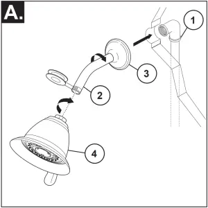
Remove Existing Shower Head
Turn the existing shower head counter-clockwise with adjustable wrench or pliers. Use care not to unscrew the shower arm; hold the shower arm secure. Note: If your shower arm has a ball on the end of it, it will not work with this shower unit and will need to be replaced with a standard shower arm.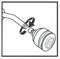
Install Shower Mount
It is recommended to wrap plumber tape (not included) around the threads of the shower arm only. Hand tighten the large end of the Shower Arm Mount clockwise onto the exposed shower arm threads until tight. Do not use a wrench or pliers.
Your shower is equipped with a Vacuum Breaker, permanently installed in the end of the hose that has a ridged nut. Hand tighten the ridged nut clockwise to the Shower Arm Mount outlet. Do not use a wrench or pliers. If you attach the ridged nut to the hand shower, the Vacuum Breaker will not function.
Note: A Vacuum Breaker is a device that is required by certain code authorities to protect your community’s water supply from the back-flow of water. The Vacuum Breaker usually discharges a small amount of water each time you turn on your shower. It may also drain water when you shut it off. Both are normal conditions – the water is draining, not leaking.
DO NOT TRY TO TIGHTEN OR REMOVE THE VACUUM BREAKER which is permanently installed into the hose. This could cause damage to the mechanism.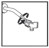
Connect Tapered End of Hose to Hand Shower
First, remove the yellow tape from the end of the hose that screws onto the hand shower. Seat the Washer firmly into the Hose nut. Carefully align the threads of the tapered end of the Hose directly to the Hand Shower. Hand tighten – do not use a wrench or pliers. Then place the Hand Shower into the Shower Arm Mount. Rotate the Shower Arm Mount into desired position to hold the Hand Shower.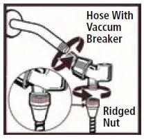
WARNING:
Plumbing Codes require that shower heads and hand showers provide a small but continuous flow of water (trickle) when in “PAUSE” mode. Because of this continuous flow, in certain circumstances pressure variations in the water line and /or changes in the position of the shower temperature control handle while in “PAUSE” mode could result in dramatic changes to the temperature of the water when the shower head or hand shower is returned to the “ON” position.
ALWAYS point the shower head away from yourself when returning to the “ON” position and feel the water with your hand before resuming your shower to ensure the water flow is not too hot or too cold. DO NOT allow children or others who might not understand this warning to use the “PAUSE” function.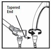
15-Year Warranty:
Delta Faucet warrants to the owner of this product that the product is free from defects in material or workmanship for the period stated above from the date of purchase.
If this product malfunctions or becomes damaged, stop use and return it to the dealer where purchased or the manufacturer (we recommend United Parcel Service):
If in the USA: If in Canada:
Alsons Corporation Masco Canada Limited
3010 West Mechanic Street 46 Bosworth Court
Hillsdale, MI 49242 Brantford, ON N3T 5N9
We will repair or replace, at our discretion, at no charge.
This warranty gives you specific legal rights. You may also have other rights that vary where you reside. For assistance with problems with installation: In the USA, call toll free 1-800-421-0001, 8:00 a.m. to 6:00 p.m. Eastern Standard Time, Monday – Friday.
]]>DELTA in2ition Shower Installation Guide

Parts Included
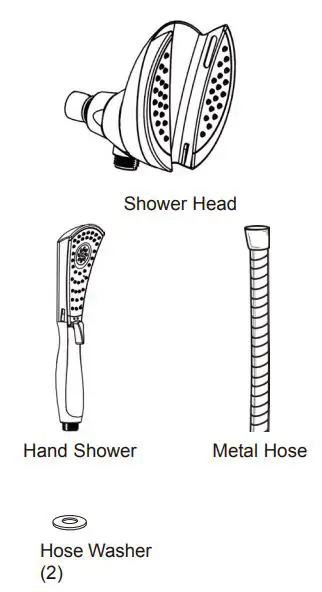
1. Install the Shower Head
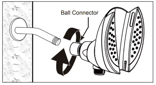
- a. Turn off water supply before installing the Shower Head.
- b. Remove existing Shower Head from Shower Arm.
- c. Apply plumber tape (not included) to Shower Arm, if necessary, to stop or prevent leaks.
- d. Hand tighten the Ball Connector of the Shower Head to the Shower Arm.
2. Install Hand Shower
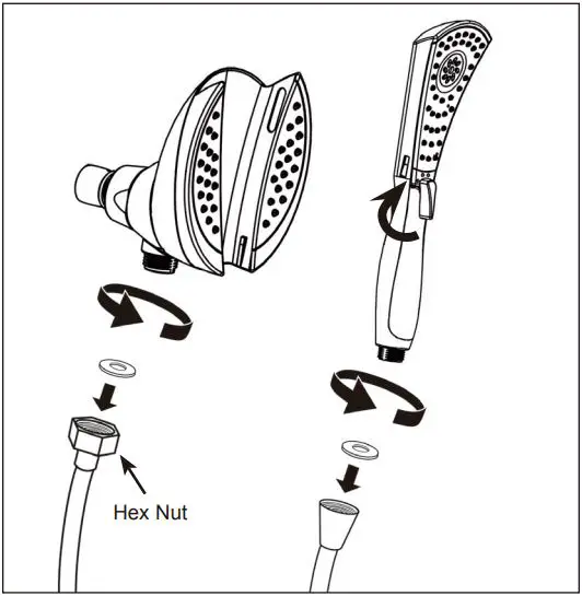
- a. Place the hose washers into the hose nuts on each end of the hose.
- b. Attach the end of the hose with a hex nut to the shower head. Connect the other end of the Metal Hose to the Hand Shower. All connections should be able to be made by hand tightening only.
- c. To change spray modes, turn the lever (located on the front of the Hand Shower) left or right to the desired setting.
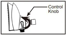
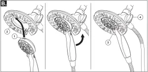
2a. Changing Modes From Shower Head, to Hand Shower, or to Both
- a. Turn knob on side of Shower Head to change between:
- Shower Head only
- Shower Head and Hand Shower
- Hand Shower only
3. Insert Hand Shower into Shower Head
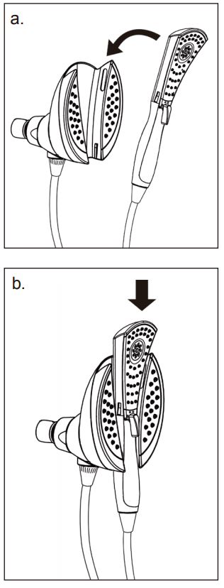
- a. Slide Hand Shower into the top of the Shower Head.
- b. Gently push the Hand Shower down into the Shower Head.
- If the Shower Head moves when inserting or removing the Hand Shower, hand tighten the connection between the Shower Head and the Ball Connector.
4. Removing the Hand Shower from the Shower Head
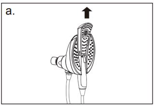
a. Push the lower part of the hand shower upwards, away from the Shower Head.
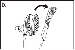
b. Pull the Hand Shower away from the slot in the Shower Head.
Notice: Removal of or tampering with the flow restrictor may result in showerhead failure and will void the warranty.
Backflow Protection
If your product is not equipped with backflow prevention, in order to make your product backflow compliant, a vacuum breaker will need to be added.
WARNING: Plumbing Codes require that shower heads and hand showers provide a small but continuous flow of water (trickle) when in “PAUSE” mode. Because of this continuous flow, in certain circumstances pressure variations in the water line and/or changes in the position of shower temperature control handle while in “PAUSE” mode could result in dramatic changes to the temperature of the water when the shower head or hand shower is returned to the “ON” position.
ALWAYS point the shower head away from yourself when returning to the “ON” position and feel the water with your hand before resuming your shower to ensure the water flow is not too hot or too cold. DO NOT allow children or others who might not understand this warning to use the “PAUSE” function.
Limited Warranty on Delta® Faucets
Parts and Finish. All parts (other than electronic parts and batteries) and finishes of Delta® faucets purchased from authorized Delta sellers are warranted to the original consumer purchaser to be free from defects in material and workmanship for as long as the original consumer purchaser owns the home in which the faucet was first installed. For commercial purchasers, (a) the warranty period is ten (10) years for multi-family residential applications and (b) five (5) years for all other commercial applications, in each case from the date of original purchase. For purposes of this warranty, the term “multi-family residential application” refers to the purchase of the faucet from an authorized Delta seller by a purchaser who owns but does not live in the residential dwelling in which the faucet is initially installed, such as in a rented or leased single unit or multi-unit detached home (duplex or townhome), or a condominium, apartment building or community living center. The following installations are not considered multi-family residential applications, are excluded from the 10-year warranty and are subject to the 5-year warranty: industrial, institutional or other business premises, such as a dormitory, hospitality premises (hotel, motel or extended stay location), airport, educational facility, long- or short-term healthcare facility (hospital, rehabilitation center, nursing, assisted or staged-care living unit), public space or common area.
Parts and Finish for Delta® Recertified Faucets. Delta Faucet Company offers for sale on deltafaucet.com Delta® Recertified faucets. All parts (other than electronic parts and batteries) and finishes of these Delta® Recertified faucets are warranted to the original consumer purchaser to be free from defects in material and workmanship for ten (10) years from the date of original purchase. For commercial purchasers, the warranty period is one (1) year from the date of original purchase.
Electronic Parts. Electronic parts (other than batteries), if any, of Delta® faucets purchased from deltafaucet.com or authorized Delta sellers are warranted to the original consumer purchaser to be free from defects in material and workmanship for five (5) years from the date of original purchase or, for commercial purchasers, for one (1) year from the date of original purchase. No warranty is provided on batteries.
What We Will Do. Delta Faucet Company will repair or replace, free of charge, during the applicable warranty period (as described above), any part or finish that proves defective in material and/or workmanship under normal installation, use and service. If repair or replacement is not practical, Delta Faucet Company may elect to refund the purchase price in exchange for the return of the product. These are your
exclusive remedies.
What Is Not Covered. Because Delta Faucet Company is unable to control the quality of Delta products sold by unauthorized sellers, unless otherwise prohibited by law, this warranty does not cover Delta products purchased from unauthorized sellers.
Any labor charges incurred by the purchaser to repair, replace, install or remove this product are not covered by this warranty. Delta Faucet Company shall not be liable for any damage to the faucet resulting from reasonable wear and tear, outdoor use, misuse (including use of the product for an unintended application), freezing water, abuse, neglect or improper or incorrectly performed installation, maintenance or repair, including failure to follow the applicable care and cleaning instructions. Delta Faucet Company recommends using a professional plumber for all installation and repair of faucets. We also recommend that you use only genuine Delta® replacement parts.
What You Must Do To Obtain Warranty Service or Replacement Parts. A warranty claim may be made and replacement parts may be obtained by calling 1 800 345 DELTA (3358) or by contacting us by mail or online as follows (please include your model number and date of
original purchase):
In the United States and Mexico:
Delta Faucet Company
Product Service
55 E. 111th Street
Indianapolis, IN 46280
Attention: Customer Solutions
www.deltafaucet.com/service-parts/contact-us
In Canada:
Masco Canada Limited, Plumbing Group
Technical Service Centre
350 South Edgeware Road
St. Thomas, Ontario, Canada N5P 4L1
Attention: Customer Service
http://www.deltafaucet.ca/customersupport/assistance.html
Proof of purchase (original sales receipt) from the original purchaser must be made available to Delta Faucet Company for all warranty claims unless the purchaser has registered the product with Delta Faucet Company or the product is a Delta® Recertified product purchased from deltafaucet.com. This warranty applies only to Delta® faucets manufactured after January 1, 2019 and installed in the United States of America, Canada and Mexico.
Limitation on Duration of Implied Warranties. Please note that some states/provinces (including Quebec) do not allow limitations
on how long an implied warranty lasts, so the below limitations may not apply to you. TO THE MAXIMUM EXTENT PERMITTED BY APPLICABLE LAW, ANY IMPLIED WARRANTY, INCLUDING THE IMPLIED WARRANTIES OF MERCHANTABILITY AND OF FITNESS FOR A PARTICULAR PURPOSE, IS LIMITED TO THE STATUTORY PERIOD OR THE DURATION OF THIS WARRANTY, WHICHEVER IS SHORTER.
Limitation of Special, Incidental or Consequential Damages. Please note that some states/provinces (including Quebec) do not allow the exclusion or limitation of special, incidental or consequential damages, so the below limitations and exclusions may not apply to you. TO THE MAXIMUM EXTENT PERMITTED BY APPLICABLE LAW, THIS WARRANTY DOES NOT COVER, AND DELTA FAUCET COMPANY SHALL NOT BE LIABLE FOR, ANY SPECIAL, INCIDENTAL OR CONSEQUENTIAL DAMAGES (INCLUDING LABOR CHARGES TO REPAIR, REPLACE, INSTALL OR REMOVE THIS PRODUCT), WHETHER ARISING OUT OF BREACH OF ANY EXPRESS OR IMPLIED WARRANTY, BREACH OF CONTRACT, TORT, OR OTHERWISE. DELTA FAUCET COMPANY SHALL NOT BE LIABLE FOR ANY DAMAGE TO THE FAUCET RESULTING FROM REASONABLE WEAR AND TEAR, OUTDOOR USE, MISUSE (INCLUDING USE OF THE PRODUCT FOR AN UNINTENDED APPLICATION), FREEZING WATER, ABUSE, NEGLECT OR IMPROPER OR INCORRECTLY PERFORMED INSTALLATION, MAINTENANCE OR REPAIR, INCLUDING FAILURE TO FOLLOW THE APPLICABLE INSTALLATION, CARE AND CLEANING INSTRUCTIONS. Notice to residents of the State of New Jersey: The provisions of this warranty, including its limitations, are intended to apply to the fullest extent permitted by the laws of the State of New Jersey.
Additional Rights. This warranty gives you specific legal rights, and you may also have other rights which vary from state/province to state/province.
This is Delta Faucet Company’s exclusive written warranty and the warranty is not transferable.
If you have any questions or concerns regarding our warranty, please contact us as provided above or view our Warranty FAQs at www.deltafaucet.com
Cleaning and Care
Care should be given to the cleaning of this product. Although its finish is extremely durable, it can be damaged by harsh abrasives or polish. To clean, simply wipe gently with a damp cloth and blot dry with a soft towel.
DELTA 106557 Single Handle Pull-Out Kitchen Faucet

Register Online: www.deltafaucet.com/registerme
To reference replacement parts and access additional technical documents and product info, visit www.deltafaucet.com
1-800-345-3358 [email protected]
Read all instructions prior to installation.
CAUTION
Failure to read these instructions prior to installation may result in personal injury, property damage, or product failure. Manufacturer assumes no responsibility for product failure due to improper installation.
WARNING:
this faucet is not to be used with portable dishwashers.
You may need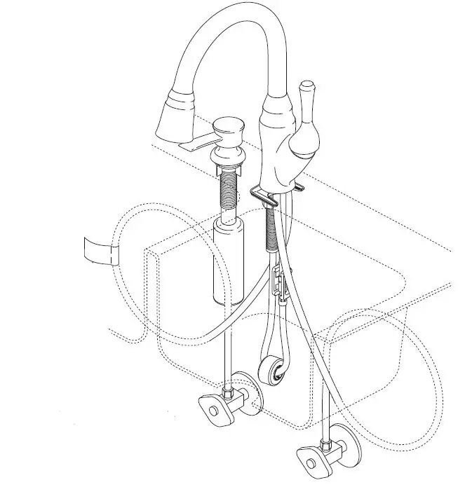
Cleaning and Care
Care should be given to the cleaning of this product. Although its finish is extremely durable, it can be damaged by harsh abrasives or polish. To clean, simply wipe gently with a damp cloth and blot dry with a soft towel.
Note: ShieldSpray® not included with all models.
Delta® ShieldSpray® Technology cuts through stubborn messes with a concentrated stream and contains the splatter with an innovative water shield. Now you can power off the mess without making a bigger one.
SINGLE HOLE MOUNTING HARDWARE(S)
(1), (2) & (3)
Mounts above deck/sink and under the faucet hub. Be sure to align trim ring tabs (4) (if your faucet has a trim ring) in base of the hub.
Thin Deck Aid RP37490 is not included with all models. Use to provide stiffness to thin gauge sinks. – To order, visit www.deltafaucet.com. Open your faucet package and determine what type of gasket (1) gasket & trim ring (2), or gasket, base ring & trim ring (3) plus mounting hardware and tools (5) that will be required to install your faucet based on the illustrations above compared to your supplied hardware.’
OPTIONAL
Optional Escutcheon Installation
Not included with all models – To order, visit www.deltafaucet.com. For installations using the 10″ escutcheon, be certain and use the 10″ escutcheon (1) and under cover plate (2). Assemble under cover plate and escutcheon in place of single hole trim ring. Place the shanks (3) of the escutcheon/under cover plate assembly into the mounting holes of the sink. Slide the tubes and shank of the hub (4) through the escutcheon and mounting holes, then install hub onto escutcheon. Ensure that tabs (5) on escutcheon and plate are properly located in slots in bottom of hub. Mount as shown above using the nuts (6), bracket (7) and nut with wrench (8).
Connection
Standard Connections
NOTICE
To avoid risk of property damage, Follow instructions for proper installation. Failure to follow these instructions may result in risk of property damage caused by leaking at this connection. Do not use pipe dope or other sealants on water line connections.
Ensure all fittings and end connections are free of debris. Faucet fittings (1) are 3/8″ compression. Loop tubing (2) if it is too long. Note: Recommended tubing minimum bend diameter is 8″. Secure metal nut (3) to supply valve connection (4). Turn nut until it feels snug. Then tighten nut at least 2 more turns with a wrench. Repeat for other tube. Turn on water, examine for leaks.
Custom Fit Connections
NOTICE
If you determine the PEX supply tubing for this faucet is too long and must be shorter to create an acceptable installation, be sure to read the instructions and plan ahead. When cutting the supply tubing the installer accepts the responsibility to do so in a way that allows a leak-free joint to be created. Delta is not responsible for tubing that is cut too short or cut in a way that will not allow for a leak-free joint. DO NOT use a metal sleeve (ferrule) or gasket (supplied with faucet) in place of the plastic sleeve (ferrule) supplied, it may not create a leak-free joint. Do not use pipe dope or other sealants on water line connections.
For custom fit installations, you must use plastic sleeves (ferrules) supplied with model and nuts included on supply lines. Tube cut must be straight. See plastic sleeve (ferrule) installation instructions found in and included in this document for more information.
Slide nut (1) over plastic sleeve (ferrule) (3). Start nut by hand onto supply valve connection (2) to prevent cross-threading. Turn nut until it feels snug. Then tighten nut at least 2 more turns with a wrench. Repeat for other supply line. Turn on water, examine for leaks.
Potential Problems and Remedies
- Tubing is not cut perpendicular to the axis of the tube: carefully make an additional cut, being careful not to cut the tube too short.
- Tubing is cut too short: buy a coupling union and a replacement supply line that mate together from a store. The coupling union end intended to connect to the faucet must mate to the standard 3/8″ connection nuts and plastic sleeves (ferrules) supplied with the faucet.
- The plastic sleeve (ferrule) or connection nut is lost: purchase a replacement nut and/or plastic sleeve (ferrule) that are designed to seal with PEX tubing.
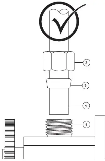
Correct method
NOTICE
Failure to use plastic sleeve (ferrule) in the correct orientation will result in disconnection and possible water damage.
- Determine desired length of supply tube (1). Leave 1″ or 2″ of extra length to allow for easier installation and cut tube. Ensure cut is straight and burr free.
- Slide nut (2) and plastic sleeve (ferrule) (3) onto cut supply tube. Ensure plastic sleeve (ferrule) is oriented as shown.
- Insert supply tube into supply valve connection (4). Supply tube should touch bottom of hole inside supply valve.
- Slide plastic sleeve (ferrule) down supply tube until it contacts the supply valve connection.
- Slide nut over plastic sleeve (ferrule). Start nut by hand to prevent cross-threading. Turn nut until it feels snug. Then tighten nut at least 2 more turns with a wrench. Repeat for other supply line. Turn on water, examine for leaks.
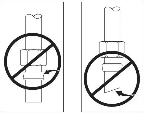
Incorrect Installation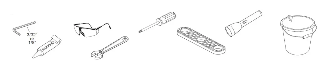 Do not install sleeve upside down.
Ensure cut is straight.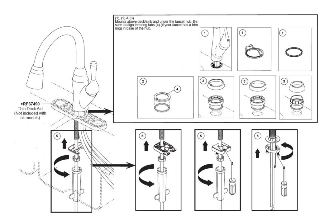 Do not use gasket (1) supplied with PEX tubing or brass ferrule (2) supplied with valve stops.
Ensure tube is fully inserted into stop before sliding sleeve down to engage top of fitting.
Flush Supply Lines
- A. Place a bucket below outlet tube (1) and move the valve handle (2) to the open mixed position.
Note: To turn on faucet, pull the lever away from the faucet. - B. Then, while holding the outlet tube (1) over the bucket, slowly open and close the supply stops (3). This will prevent debris from being lodged in the hose and sprayer.
- C. Move faucet handle (2) to the off position, and carefully remove container of water.
Hose Installation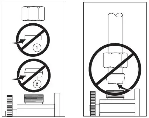
- A. Insert hose end (1) through hose weight assembly (2).
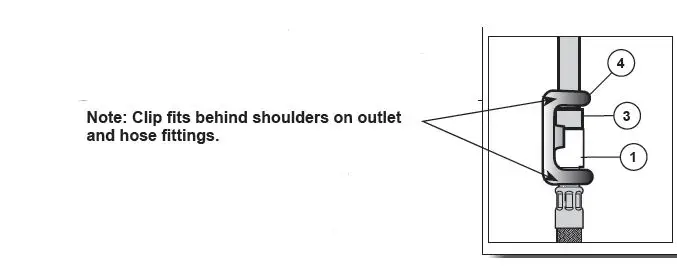
- B. Push hose end (1) onto faucet outlet (3). Attach clip (4) over hose and outlet as shown. Pull down moderately to ensure connection has been made.
B. Side View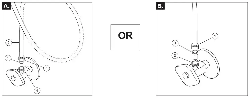
Setting The Handle Limit Stop (Optional) – not supplied with all models
This faucet includes an integrated handle limit stop that has two positions. Position 1, to the left, allows full handle motion (the full range between “all cold” to “all hot”). The faucet is set in position 1 in the factory. Position 2, to the right, allows half of the normal handle motion (“all cold” to “mixed hot/cold”).
Soap Dispenser Installation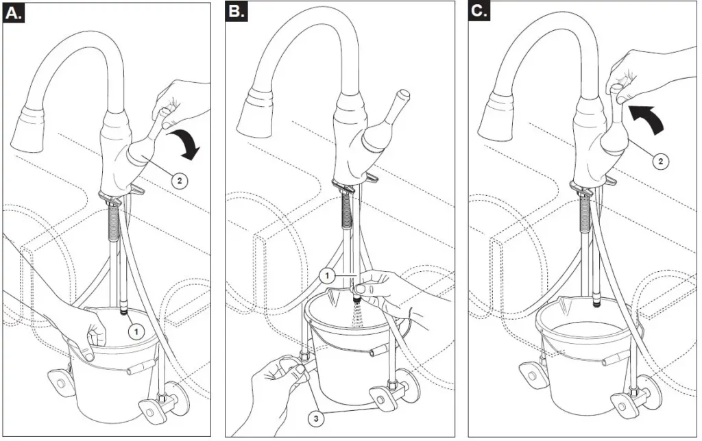 Note: Soap dispenser not included with all models.
Remove nut (1). Separate head (2) from body (3). Insert body (3) and gasket (4) through selected hole in sink. Make sure gasket (4) is properly seated in the base. Secure body to sink with nut (1). From under the sink screw the bottle (5) onto the body assembly shank. Insert pump (6) into head (2), then drop into body (3). NOTE: To fill, lift the head and pump assembly out of the bottle and pour not more than 8 oz. into bottle. DO NOT remove bottle each time as this weakens the neck. Pull pump and head assembly out occasionally to soak and pump warm water through pump to remove soap build-up. Note: Initially it may take up to 12 pumps to bring soap to the pump tip.
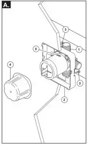
A. Turn on water supplies (1) and faucet valve handle (2). Check all connections at arrows for leaks. Refer back to the appropri-ate installation instructions and retighten if necessary. If assembled correctly, check for damage to seals and order appropriate replacements.
B. Sprayer will lock into position when brought into proximity of the spout magnet. The sprayer can be removed by either pulling directly out from the spout or by twisting 90° in either direction which will cause the magnets to repel and the head to decouple from the spout (recommended).
Check the operation of the 2 function sprayer by pushing the trigger (A) from aerator to spray. For models with a 3 function sprayer, check the operation by pushing the buttons to achieve the 3 different modes.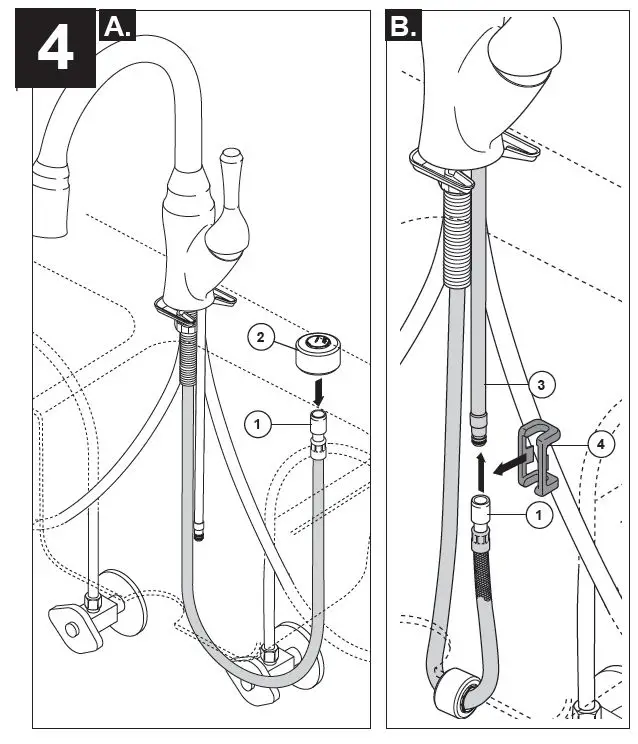
Maintenance
If faucet exhibits very low flow
- A. Remove and clean aerator (1) (Note: some models are not supplied with an areator or a wrench is required (2) to remove aerator.), or
- B. Unscrew hose from spray head and clean debris from screen (the screen is located just inside the spray head (3). Note: Not all models have screens. IMPORTANT: Reinstall screen to the spray head. (Failure to reinstall the screen could damage internal parts.)
If faucet leaks from under handle: Remove handle (4) and cap (5). Using a wrench, ensure bonnet nut (6) is tight.
If leak persists–SHUT OFF WATER SUPPLIES. Replace valve cartridge (7). When reinstalling parts, make sure bonnet nut (6) is tightened securely with a wrench.*
If faucet leaks from spout outlet–SHUT OFF WATER SUPPLIES. Replace valve cartridge (7). When reinstalling parts, make sure bonnet nut (6) is tightened securely with a wrench.*
WARNING: Failure to securely tighten bonnet nut with a wrench could result in water damage.
Note: A small amount of water may run out the spout or drip for a very short period after the faucet is shut off. This is a natural occurrence caused by the long flexible hose.
Note: Do not attempt to disassemble cartridge (7). There are no repairable parts inside.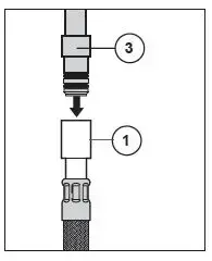 Maintenance
If faucet exhibits very low flow – Unscrew hose from spray head and clean debris from screen (1) (the screen is located just inside the spray) . IMPORTANT: Reinstall screen to the spray head (failure to reinstall the screen could damage internal parts).
If faucet leaks from under handle or from spout outlet – Insert a small screwdriver into slot (2) in button (3) and remove. Loosen set screw (4) inside of handle. Remove handle. Remove cap (5) by rotating counterclockwise. Bonnet may be stiff due to O-ring, but should rotate by hand. Remove bonnet nut (6) by rotating counterclockwise with a wrench. Remove cartridge (7) by pulling directly back on stem. Replace cartridge and reassemble.
WARNING: Failure to securely tighten bonnet nut with a wrench could result in water damage.
Note: A small amount of water may run out the spout or drip for a very short period after the faucet is shut off. This is a natural occurrence caused by the long flexible hose.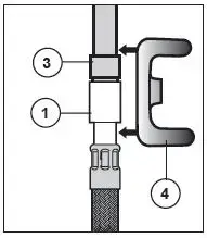
3 Function Wand
- Button 1 – Standard Flow Aerator
- Button 2 – 1.5 gpm at 60 psi Maximum Aerator
- Button 3 – Spray Mode
- Note – 3 Function Sprayer returns to position 2 if left in position 1 when the water is turned off.
ShieldSpray® Models
- Button 1 – ShieldSpray Mode
- Button 2 – Spray Mode
- Button 3 – 1.8 gpm at 60 psi Maximum Aerator
- Note – 3 Function Sprayer returns to position 3 when button 1 is released.
C. With the wand undocked, press button 1 to use the ShieldSpray mode.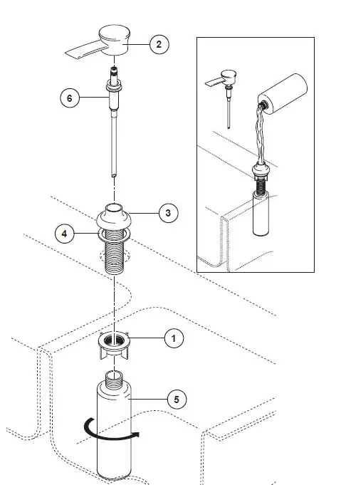 Hold the plate 1/2 way through the bubble.
For optimal performance, use in households with water pressure above 35 psi. The ShieldSpray feature may appear different at lower water pressures.
Tip: Don’t push the button while docked – always pull it close to the plate.
Limited Warranty on Delta® Faucets
Parts and Finish. All parts (other than electronic parts and batteries) and finishes of Delta® faucets purchased from authorized Delta sellers are warranted to the original consumer purchaser to be free from defects in material and workmanship for as long as the original consumer purchaser owns the home in which the faucet was first installed. For commercial purchasers, (a) the warranty period is ten (10) years for multi-family residential applications and (b) five (5) years for all other commercial applications, in each case from the date of original pur-chase. For purposes of this warranty, the term “multi-family residential application” refers to the purchase of the faucet from an authorized Delta seller by a purchaser who owns but does not live in the residential dwelling in which the faucet is initially installed, such as in a rented or leased single unit or multi-unit detached home (duplex or townhome), or a condominium, apartment building or community living center. The following installations are not considered multi-family residential applications, are excluded from the 10-year warranty and are subject to the 5-year warranty: industrial, institutional or other business premises, such as a dormitory, hospitality premises (hotel, motel or extended stay location), airport, educational facility, long- or short-term healthcare facility (hospital, rehabilitation center, nursing, assisted or staged-care liv-ing unit), public space or common area.
Parts and Finish for Delta® Recertified Faucets. Delta Faucet Company offers for sale on deltafaucet.com Delta® Recertified faucets. All parts (other than electronic parts and batteries) and finishes of these Delta® Recertified faucets are warranted to the original consumer pur-chaser to be free from defects in material and workmanship for ten (10) years from the date of original purchase. For commercial purchasers, the warranty period is one (1) year from the date of original purchase.
Electronic Parts. Electronic parts (other than batteries), if any, of Delta® faucets purchased from deltafaucet.com or authorized Delta sell-ers are warranted to the original consumer purchaser to be free from defects in material and workmanship for five (5) years from the date of original purchase or, for commercial purchasers, for one (1) year from the date of original purchase. No warranty is provided on batteries.
What We Will Do. Delta Faucet Company will repair or replace, free of charge, during the applicable warranty period (as described above), any part or finish that proves defective in material and/or workmanship under normal installation, use and service. If repair or replacement is not practical, Delta Faucet Company may elect to refund the purchase price in exchange for the return of the product. These are your exclusive remedies.
What Is Not Covered. Because Delta Faucet Company is unable to control the quality of Delta products sold by unauthorized sellers, unless otherwise prohibited by law, this warranty does not cover Delta products purchased from unauthorized sellers.
Any labor charges incurred by the purchaser to repair, replace, install or remove this product are not covered by this warranty. Delta Faucet Company shall not be liable for any damage to the faucet resulting from reasonable wear and tear, outdoor use, misuse (including use of the product for an unintended application), freezing water, abuse, neglect or improper or incorrectly performed installation, maintenance or repair, including failure to follow the applicable care and cleaning instructions. Delta Faucet Company recommends using a professional plumber for all installation and repair of faucets. We also recommend that you use only genuine Delta® replacement parts.
What You Must Do To Obtain Warranty Service or Replacement Parts. A warranty claim may be made and replacement parts may be obtained by calling 1 800 345 DELTA (3358) or by contacting us by mail or online as follows (please include your model number and date of original purchase):
In the United States and Mexico:
Delta Faucet Company
Product Service
55 E. 111th Street
Indianapolis, IN 46280
Attention: Customer Solutions
www.deltafaucet.com/service-parts/contact-us
In Canada:
Masco Canada Limited, Plumbing Group
Technical Service Centre
350 South Edgeware Road
St. Thomas, Ontario, Canada N5P 4L1
Attention: Customer Service
http://www.deltafaucet.ca/customersupport/assistance.html
Proof of purchase (original sales receipt) from the original purchaser must be made available to Delta Faucet Company for all warranty claims unless the purchaser has registered the product with Delta Faucet Company or the product is a Delta® Recertified product purchased from deltafaucet.com. This warranty applies only to Delta® faucets manufactured after January 1, 2019 and installed in the United States of America, Canada and Mexico.
Limitation on Duration of Implied Warranties. Please note that some states/provinces (including Quebec) do not allow limitations on how long an implied warranty lasts, so the below limitations may not apply to you. TO THE MAXIMUM EXTENT PERMITTED BY APPLICABLE LAW, ANY IMPLIED WARRANTY, INCLUDING THE IMPLIED WARRANTIES OF MERCHANTABILITY AND OF FITNESS FOR A PARTICULAR PURPOSE, IS LIMITED TO THE STATUTORY PERIOD OR THE DURATION OF THIS WARRANTY, WHICHEVER IS SHORTER.
Limitation of Special, Incidental or Consequential Damages. Please note that some states/provinces (including Quebec) do not allow the exclusion or limitation of special, incidental or consequential damages, so the below limitations and exclusions may not apply to you. TO THE MAXIMUM EXTENT PERMITTED BY APPLICABLE LAW, THIS WARRANTY DOES NOT COVER, AND DELTA FAUCET COMPANY SHALL NOT BE LIABLE FOR, ANY SPECIAL, INCIDENTAL OR CONSEQUENTIAL DAMAGES (INCLUDING LABOR CHARGES TO REPAIR, REPLACE, INSTALL OR REMOVE THIS PRODUCT), WHETHER ARISING OUT OF BREACH OF ANY EXPRESS OR IMPLIED WARRANTY, BREACH OF CONTRACT, TORT, OR OTHERWISE. DELTA FAUCET COMPANY SHALL NOT BE LIABLE FOR ANY DAMAGE TO THE FAUCET RESULTING FROM REASONABLE WEAR AND TEAR, OUTDOOR USE, MISUSE (INCLUDING USE OF THE PRODUCT FOR AN UNINTENDED APPLICATION), FREEZING WATER, ABUSE, NEGLECT OR IMPROPER OR INCORRECTLY PERFORMED INSTALLATION, MAINTENANCE OR REPAIR, INCLUDING FAILURE TO FOLLOW THE APPLICABLE INSTALLATION, CARE AND CLEANING INSTRUCTIONS. Notice to residents of the State of New Jersey: The provisions of this warranty, including its limitations, are intended to apply to the fullest extent permitted by the laws of the State of New Jersey.
Additional Rights. This warranty gives you specific legal rights, and you may also have other rights which vary from state/province to state/province.
This is Delta Faucet Company’s exclusive written warranty and the warranty is not transferable.
If you have any questions or concerns regarding our warranty, please contact us as provided above or view our Warranty FAQs at www. deltafaucet.com.
To reference replacement parts and access additional technical documents and product info, visit www.deltafaucet.com
Read all instructions prior to installation.
Failure to read these instructions prior to installation may result in personal injury, property damage, or product failure. Manufacturer assumes no responsibility for product failure due to improper installation.
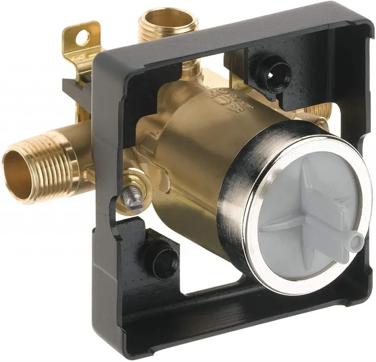
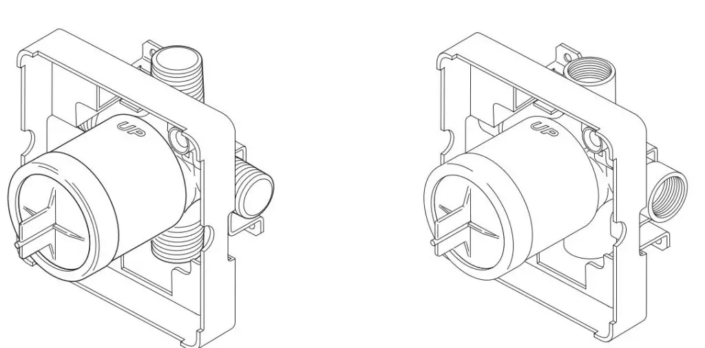
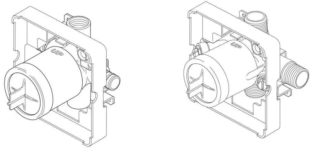
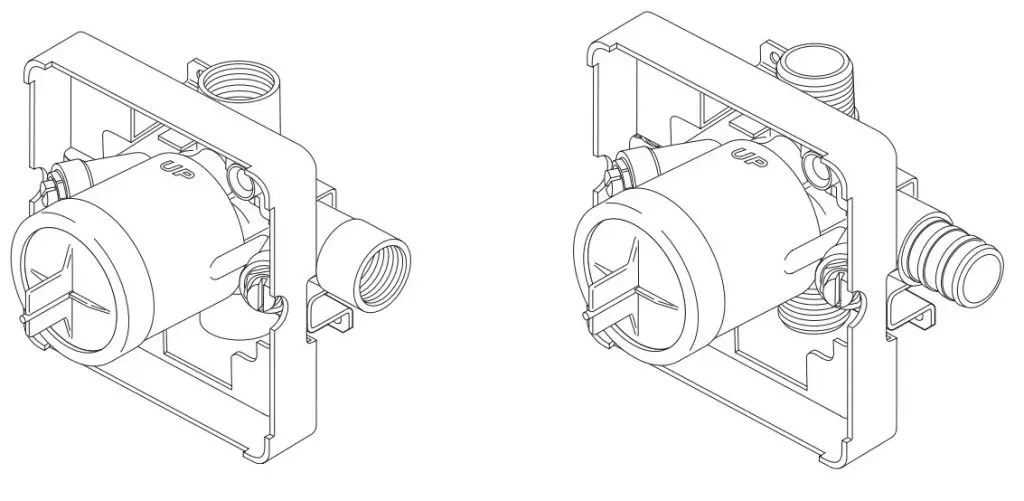
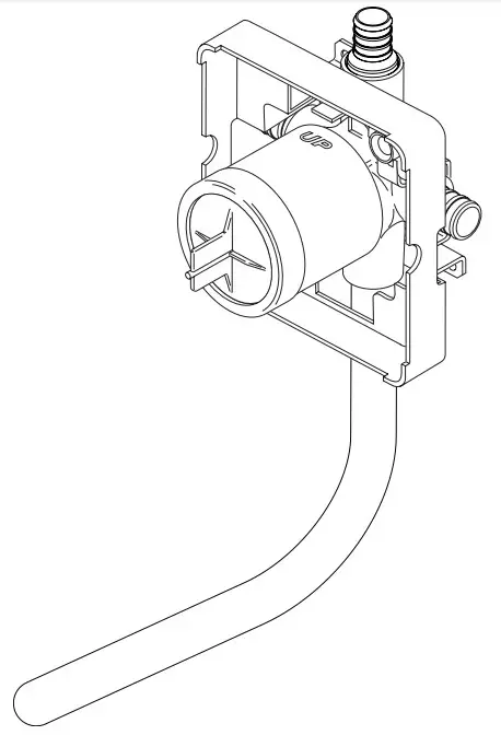
MULTICHOICE® ROUGH-IN BODY

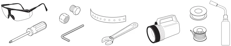
You may need:
SHUT OFF WATER SUPPLIES:
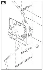
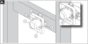
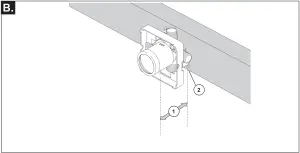
your finished wall before placing your stringer back plate. Install the body (1) so the surface of the finished wall is flush with the front of the plasterguard (2) ± 1/4″.
For with stops models, plasterguard must be flush or subflush 1/4″ to finished wall. Mount body using the two stringer mounting holes (3) on the bracket.
Remove cover (4) to access mounting holes. Make sure the word “UP” (5) is on top of the valve bodywhen installing.
Distance (1) from the stringer (2) to the front of the plasterguard is 2 3/4″ ± 1/4″ (70 mm ± 6 mm).
This is the same distance to the finished wall (3). Distance (4) from the stringer (2) to the front of the bonnet is 3 7/8″ (99 mm).
(For reference only)
If a thin wall is used, be sure to have the plasterguard behind the wall, otherwise the wall should always be flush with the front of the plasterguard. See instruction on the bag for thin wall mounting.
For thin wall installation, RP47202 might be needed
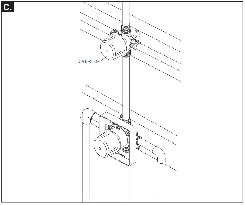
The figure illustrates the diverter and MultiChoice installed in the same finished wall.
Refer to the diverter rough installation instructions for more information.
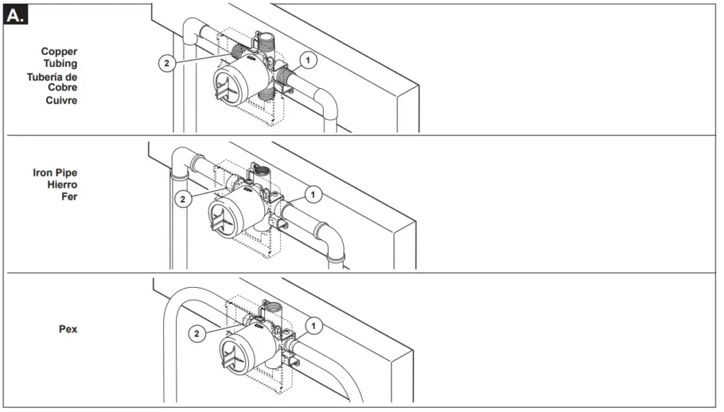
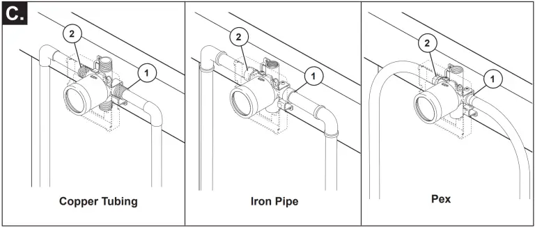
Connect valve body to water supplies using the proper fittings for your valve body type (copper tubing, iron pipe or Pex).
For Pex, be sure to use the right fitting for crimping and the right tool for cold expansion. If either of the two outlet ports is to be unused, seal the port with a pipe plug. Note: (1) is the cold inlet port and (2) is the hot inlet port.
If you are making a back to back or reverse installation (hot on right and cold on left) install the valve body as described, but the water supply lines will be reversed.
(1) is the hot inlet port and (2) is the cold inlet port.
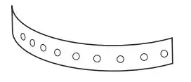
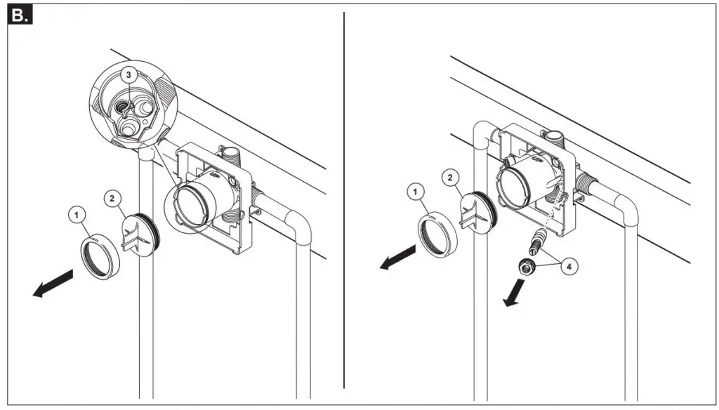
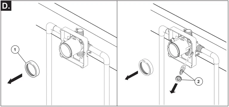
Remove bonnet (1) and test cap (2) before soldering. Leave screen (3) installed.
Avoid soldering at high temperature. Exposure to high temperatures may damage screen. Be sure stops (4) are removed from the w/stops version before soldering. (Do not install before soldering.)
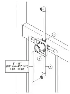
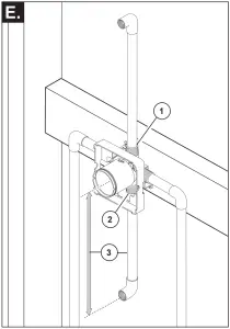
Connect top outlet (1) to shower pipe with proper fittings. Connect bottom outlet (2) to tub spout pipe with proper fittings. Pipe (3) between valve body and tub spout must be a minimum of 1/2″ (13 mm) copper pipe or 1/2″ (13 mm) iron pipe in a straight drop no less than 8″ (203 mm) but no more than 18″ (457 mm) long with only one iron pipe or copper 90 degree elbow to the tub spout nipple. Do not use PEX tubing for tub spout drop. Note: There is no tub outlet in high flow models.
PRESSURE TESTING & FLUSHING THE INSTALLATION
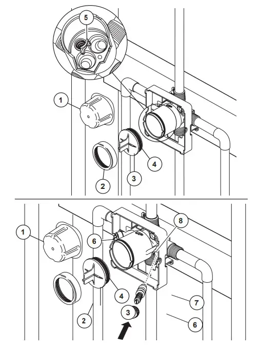
Prior to testing, remove cover (1), bonnet (2) and cap (3). Ensure O-ring (4) and filter screen (5) are properly installed. Reinstall cap and bonnet and tighten securely. Plug both outlets with proper fittings. Check for leaks. After testing remove shower and/or tub spout plug and flush system. After flushing remove filter screen (5) and reinstall cap, bonnet and cover. Install stops (6 & 7) in the w/stops version and set to full open. Note: Install stops in the w/stops version as follows:
Thread nut (6) on stem (7) as shown. Then press stem and nut assembly into body (8) and tighten using a 3/8″, 6 point, deep well socket. With a flat head screwdriver, adjust stem clockwise to close and counterclockwise to open.
Cleaning and Care
Care should be given to the cleaning of this product. Although its finish is extremely durable, it can be damaged by harsh abrasives or polish. To clean, simply wipe gently with a damp cloth and blot dry with a soft towel.
Limited Warranty on Delta® Faucets
Parts and Finish. All parts (other than electronic parts and batteries) and finishes of Delta® faucets purchased from authorized Delta sellers are warranted to the original consumer purchaser to be free from defects in material and workmanship for as long as the original consumer purchaser owns the home in which the faucet was first installed. For commercial purchasers, (a) the warranty period is ten (10) years for multi-family residential applications and (b) five (5) years for all other commercial applications, in each case from the date of original purchase. For purposes of this warranty, the term “multi-family residential application” refers to the purchase of the faucet from an authorized Delta seller by a purchaser who owns but does not live in the residential dwelling in which the faucet is initially installed, such as in a rented or leased single unit or multi-unit detached home (duplex or townhome), or a condominium, apartment building or community living center. The following installations are not considered multi-family residential applications, are excluded from the 10-year warranty and are subject to the 5-year warranty: industrial, institutional or other business premises, such as a dormitory, hospitality premises (hotel, motel or extended stay location), airport, educational facility, long- or short-term healthcare facility (hospital, rehabilitation center, nursing, assisted or staged-care living unit), public space or common area
Parts and Finish for Delta® Recertified Faucets. Delta Faucet Company offers for sale on deltafaucet.com Delta® Recertified faucets. All parts (other than electronic parts and batteries) and finishes of these Delta® Recertified faucets are warranted to the original consumer purchaser to be free from defects in material and workmanship for ten (10) years from the date of original purchase. For commercial purchasers, the warranty period is one (1) year from the date of original purchase.
Electronic Parts. Electronic parts (other than batteries), if any, of Delta® faucets purchased from deltafaucet.com or authorized Delta sellers are warranted to the original consumer purchaser to be free from defects in material and workmanship for five (5) years from the date of original purchase or, for commercial purchasers, for one (1) year from the date of original purchase. No warranty is provided on batteries.
What We Will Do. Delta Faucet Company will repair or replace, free of charge, during the applicable warranty period (as described above), any part or finish that proves defective in material and/or workmanship under normal installation, use and service. If repair or replacement is not practical, Delta Faucet Company may elect to refund the purchase price in exchange for the return of the product. These are your exclusive remedies
In the United States and Mexico:
Delta Faucet Company
Product Service
55 E. 111th Street
Indianapolis, IN 46280
Attention: Customer Solutions
www.deltafaucet.com/service-parts/contact-us
MultiChoice® Valve Trim
Owners Manual
17 Series
107529

____________________________
Write purchased model number here.
You May Need

For additional replacement parts, visit www.deltafaucet.com
THIS VALVE MEETS OR EXCEEDS THE FOLLOWING STANDARDS: ASME A112.18.1/CSA B125.1 and ASSE 1016 (Type -P- or -T-).
CAUTION: This system/device must be set by the installer to ensure safe, maximum temperature. Any change in the setting may raise the discharge temperature above the limit considered safe and may lead to hot water burns.
CAUTION!–As the installer of this valve, it is your responsibility to properly INSTALL and ADJUST this valve per the instructions given. This valve does not automatically adjust for inlet temperature changes, therefore, someone must make the necessary Rotational Limit Stop adjustments at the time of installation and further adjustments may be necessary due to seasonal water temperature change. YOU MUST inform the owner/user of this requirement by following the instructions. If you or the owner/user are unsure how to properly make these adjustments please refer to page 7 and if still uncertain, call us at 1-800-345-DELTA.
After installation and adjustment, you must affix your name, company name and the date you adjusted the Rotational Limit Stop to the caution label provided and apply or attach the label to the back side of the closest cabinet door and the warning label to the water heater. Leave this Instruction Sheet for the owner’s/user’s reference.
This pressure balanced or thermostatic bath valve is designed to minimize the effects of outlet water temperature changes due to inlet pressure changes, commonly caused by dishwashers, washing machines, toilets and the like. It may not provide protection from hot water burns when there is a failure of other temperature controlling devices elsewhere in the plumbing system, if the rotational limit stop is not properly set or if the hot water temperature is changed after the settings are made or if the water inlet changes due to seasonal changes.
Do not install a shut-off device on either outlet of this valve. When this type of device shuts off the water flow, it can defeat the ability of the valve to balance the hot and cold water pressures.
Limited Warranty on Delta® Faucets
Parts and Finish. All parts (other than electronic parts and batteries) and finishes of Delta® faucets purchased from authorized Delta sellers are warranted to the original consumer purchaser to be free from defects in material and workmanship for as long as the original consumer purchaser owns the home in which the faucet was first installed. For commercial purchasers, (a) the warranty period is ten (10) years for multi-family residential applications and (b) five (5) years for all other commercial applications, in each case from the date of original purchase. For purposes of this warranty, the term “multi-family residential application” refers to the purchase of the faucet from an authorized Delta seller by a purchaser who owns but does not live in the residential dwelling in which the faucet is initially installed, such as in a rented or leased single unit or multi-unit detached home (duplex or townhome), or a condominium, apartment building or community living center. The following installations are not considered multi-family residential applications, are excluded from the 10-year warranty and are subject to the 5-year warranty: industrial, institutional or other business premises, such as a dormitory, hospitality premises (hotel, motel or extended stay location), airport, educational facility, long- or short-term healthcare facility (hospital, rehabilitation center, nursing, assisted or staged-care living unit), public space or common area.
Parts and Finish for Delta® Recertified Faucets. Delta Faucet Company offers for sale on deltafaucet.com Delta® Recertified faucets. All parts (other than electronic parts and batteries) and finishes of these Delta® Recertified faucets are warranted to the original consumer purchaser to be free from defects in material and workmanship for ten (10) years from the date of original purchase. For commercial purchasers, the warranty period is one (1) year from the date of original purchase.
Electronic Parts. Electronic parts (other than batteries), if any, of Delta® faucets purchased from deltafaucet.com or authorized Delta sellers are warranted to the original consumer purchaser to be free from defects in material and workmanship for five (5) years from the date of original purchase or, for commercial purchasers, for one (1) year from the date of original purchase. No warranty is provided on batteries.
What We Will Do. Delta Faucet Company will repair or replace, free of charge, during the applicable warranty period (as described above), any part or finish that proves defective in material and/or workmanship under normal installation, use and service. If repair or replacement is not practical, Delta Faucet Company may elect to refund the purchase price in exchange for the return of the product. These are your exclusive remedies.
What Is Not Covered. Because Delta Faucet Company is unable to control the quality of Delta products sold by unauthorized sellers, unless otherwise prohibited by law, this warranty does not cover Delta products purchased from unauthorized sellers.
Any labor charges incurred by the purchaser to repair, replace, install or remove this product are not covered by this warranty. Delta Faucet Company shall not be liable for any damage to the faucet resulting from reasonable wear and tear, outdoor use, misuse (including use of the product for an unintended application), freezing water, abuse, neglect or improper or incorrectly performed installation, maintenance or repair, including failure to follow the applicable care and cleaning instructions. Delta Faucet Company recommends using a professional plumber for all installation and repair of faucets. We also recommend that you use only genuine Delta® replacement parts.
What You Must Do To Obtain Warranty Service or Replacement Parts. A warranty claim may be made and replacement parts may be obtained by calling 1 800 345 DELTA (3358) or by contacting us by mail or online as follows (please include your model number and date of original purchase):
In the United States and Mexico:
Delta Faucet Company
Product Service
55 E. 111th Street
Indianapolis, IN 46280
Attention: Warranty Service
www.deltafaucet.com/service-parts/contact-us
In Canada:
Masco Canada Limited, Plumbing Group
Technical Service Centre
350 South Edgeware Road
St. Thomas, Ontario, Canada N5P 4L1
Attention: Warranty Service
http://www.deltafaucet.ca/customersupport/assistance.html
Proof of purchase (original sales receipt) from the original purchaser must be made available to Delta Faucet Company for all warranty claims unless the purchaser has registered the product with Delta Faucet Company or the product is a Delta® Recertified product purchased from deltafaucet.com. This warranty applies only to Delta® faucets manufactured after January 1, 2019 and installed in the United States of America, Canada and Mexico.
Limitation on Duration of Implied Warranties. Please note that some states/provinces (including Quebec) do not allow limitations on how long an implied warranty lasts, so the below limitations may not apply to you. TO THE MAXIMUM EXTENT PERMITTED BY APPLICABLE LAW, ANY IMPLIED WARRANTY, INCLUDING THE IMPLIED WARRANTIES OF MERCHANTABILITY AND OF FITNESS FOR A PARTICULAR PURPOSE, IS LIMITED TO THE STATUTORY PERIOD OR THE DURATION OF THIS WARRANTY, WHICHEVER IS SHORTER.
Limitation of Special, Incidental or Consequential Damages. Please note that some states/provinces (including Quebec) do not allow the exclusion or limitation of special, incidental or consequential damages, so the below limitations and exclusions may not apply to you. TO THE MAXIMUM EXTENT PERMITTED BY APPLICABLE LAW, THIS WARRANTY DOES NOT COVER, AND DELTA FAUCET COMPANY SHALL NOT BE LIABLE FOR, ANY SPECIAL, INCIDENTAL OR CONSEQUENTIAL DAMAGES (INCLUDING LABOR CHARGES TO REPAIR, REPLACE, INSTALL OR REMOVE THIS PRODUCT), WHETHER ARISING OUT OF BREACH OF ANY EXPRESS OR IMPLIED WARRANTY, BREACH OF CONTRACT, TORT, OR OTHERWISE. DELTA FAUCET COMPANY SHALL NOT BE LIABLE FOR ANY DAMAGE TO THE FAUCET RESULTING FROM REASONABLE WEAR AND TEAR, OUTDOOR USE, MISUSE (INCLUDING USE OF THE PRODUCT FOR AN UNINTENDED APPLICATION), FREEZING WATER, ABUSE, NEGLECT OR IMPROPER OR INCORRECTLY PERFORMED INSTALLATION, MAINTENANCE OR REPAIR, INCLUDING FAILURE TO FOLLOW THE APPLICABLE INSTALLATION, CARE AND CLEANING INSTRUCTIONS. Notice to residents of the State of New Jersey: The provisions of this warranty, including its limitations, are intended to apply to the fullest extent permitted by the laws of the State of New Jersey.
Additional Rights. This warranty gives you specific legal rights, and you may also have other rights which vary from state/province to state/province.
This is Delta Faucet Company’s exclusive written warranty and the warranty is not transferable.
If you have any questions or concerns regarding our warranty, please contact us as provided above or view our Warranty FAQs at www.deltafaucet.com.
© 2020 Delta Faucet Company
Delta HDF Limited Warranty
All parts of the Delta HDF faucet are warranted to the original consumer purchaser to be free from defects in material and workmanship for a period of five (5) years. This warranty is made to the original consumer purchaser and shall be effective from date of purchase as shown on purchaser’s receipt.
Delta will replace, FREE OF CHARGE, during the warranty period, any part which proves defective in material and/or workmanship under normal installation, use and service. Replacement parts can be obtained from your local dealer or distributor listed in the telephone directory or by returning the part along with the purchaser’s receipt to our factory, TRANSPORTATION CHARGES PREPAID, at the address listed. THIS WARRANTY IS THE ONLY EXPRESS WARRANTY MADE BY DELTA. ANY CLAIMS MADE UNDER THIS WARRANTY MUST BE MADE DURING THE FIVE YEAR PERIOD REFERRED TO ABOVE. ANY IMPLIED WARRANTIES, INCLUDING THE IMPLIED WARRANTY OF MERCHANTABILITY OR FITNESS FOR A PARTICULAR PURPOSE, ARE LIMITED IN DURATION TO THE DURATION OF THIS WARRANTY. LABOR CHARGES AND/OR DAMAGE INCURRED IN INSTALLATION, REPAIR OR REPLACEMENT AS WELL AS INCIDENTAL AND CONSEQUENTIALDAMAGES CONNECTED THEREWITH ARE EXCLUDED AND WILL NOT BE PAID BY DELTA.
Some states do not allow limitations on how long an implied warranty lasts, or the exclusion or limitation of incidental or consequential damages, so the above limitations or exclusions may not apply to you.
This warranty gives you specific legal rights, and you may also have other rights which vary from state to state.
This warranty is void for any damage to this faucet due to misuse, abuse, neglect, accident, improper installation, any use violative of instructions furnished by us or any use of replacement parts other than genuine Delta parts.
[1] MultiChoice® Rough-In Installation (When your product requires)
SHUT OFF WATER SUPPLIES.
Consider the type and thickness of your finished wall before placing your stringer back plate. Install the body (1) so the surface of the finished wall is flush with the front of the plasterguard (2) ± 3/8″. Note: For models with stops (3), plasterguard must be flush or subflush 3/8″ to finished wall. Mount body using the two stringer mounting holes (4) on the bracket. Make sure the word “UP” (5) is on top of the valve body when installing.
Distance (1) from the stringer (2) to the front of the plasterguard is 2.8″ (71 mm).
If a thin wall is used, be sure to have the plasterguard behind the wall, otherwise the wall should always be flush with the front of the plasterguard. See instruction on the bag for thin wall mounting.
Connect valve body to water supplies using the proper fittings for your valve body type (copper tubing, iron pipe or Pex). Note: (1) is the cold inlet port and (2) is the hot inlet port. If either of the two outlet ports is to be unused, seal the port with a pipe plug.
If you are making a back to back or reverse installation (hot on right and cold on left) install the valve body as described, but the water supply lines will be reversed. Note: (1) is the hot inlet port and (2) is the cold inlet port.
Remove bonnet (1). Warning: Avoid soldering at high temperatures.
Be sure stops (2) are removed from the w/stops version before soldering. (Do not install stops before soldering.)
Connect top outlet (1) to shower pipe with proper fittings. Connect bottom outlet (2) to tub spout pipe with proper fittings. Pipe (3) between valve body and tub spout must be a minimum of 1/2″ (13 mm) copper pipe or 1/2″ (13 mm) iron pipe in a straight drop no less than 8″ (203 mm) but no more than 18″ (457 mm) long with only one iron pipe or copper 90 degree elbow to the tub spout nipple. Do not use PEX tubing for tub spout drop.
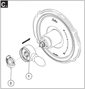
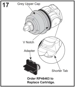
[2] Cartridge Installation
Turn off water supplies. Remove bonnet nut (1) and test cap (2) from the body. If this is not a thin wall mounting, the entire plasterguard (3) may be removed. If screen (4) is in place, remove before installing cartridge.
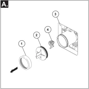
Insert adapter assembly (1) into valve body. Make sure the adapter assembly is correctly positioned and is pressed all the way down inside body. Remove the retainer (2) from the adapter.
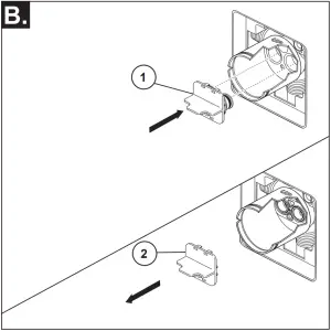
Rotate cartridge (1) so the words “HOT SIDE” (2) appear on the left. Insert cartridge assembly into valve body.
Make sure the key (3) on the cartridge is fully engaged with the slot in the brass body (4). Slide bonnet nut (5) over the cartridge and thread onto the body. Hand tighten securely.
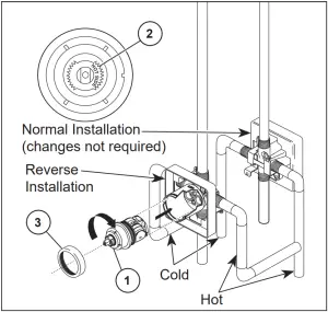
Back to back Installation
For back to back or reverse installations (hot on right and cold on left): Rotate cartridge (1) so the words “HOT SIDE” (2) appear on the right. Install the cartridge making sure that the key is fully engaged with the slot in the brass body (See step C). Slide bonnet nut (3) over the cartridge and thread onto the body. Hand tighten securely.
[3] Shower Head and Tub Spout Installation
FOR SHOWER HEAD INSTALLATION: Connect top outlet (1) to shower arm (2) with proper fittings. To prevent damage to finish on shower arm, insert wall end of shower arm into shower flange (3) before screwing arm into riser connection. Thread shower head (4) onto shower arm. Apply plumber tape to pipe threads on both ends. Do not overtighten shower head.
To combine the two showers, connect the top slot (1) of the handshower onto the tab (2) of the showerhead. Push the handshower into the showerhead until the two parts snap together.
If the showerhead moves when removing the handshower, hand tighten the connection between the showerhead and the shower arm.
To change spray modes, turn the lever/dial (3) left or right, or push button (3), to the desired setting. Turn knob or lever (4) to change between showerhead only, showerhead and handshower or handshower only.
FOR TUB SPOUT INSTALLATION:
Refer to the installation instructions supplied with your spout. Do not connect deck mount spouts to in-wall valves. Do not use hand showers connected in lieu of a tub spout to a tub/shower valve. Do not use PEX tubing for tub spout drop.
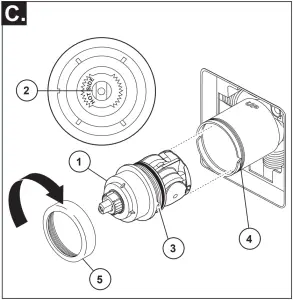
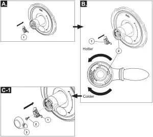
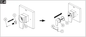
[4] Trim Installation
Slide O-ring (1) over cartridge and the bonnet nut (2). The O-ring, which acts as a spacer to steady the sleeve, should rest behind the bonnet nut. Slide the sleeve (3) over the cartridge, body and O-ring. Ensure sleeve is properly positioned over the front of cartridge.
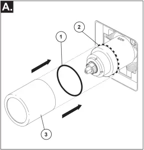
Note: Adjust for up to 1″ thick wall. For thick wall installation, visit delta faucet website, check “view technical specification” of the models you bought, order the appropriate thick wall installation kit RP to get additional 1 3/4″ wall thickness.
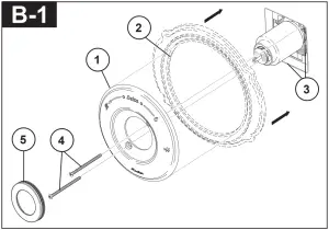
B-1: Secure the escutcheon (1) and backplate (2) (if your model has one) to the bracket (3) using the 2 screws (4) provided. Do not overtighten escutcheon screws. Press the cover (5) onto the escutcheon (1) when your product includes the cover.
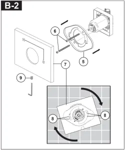
B-2: Install bracket (5) over the cartridge body using the 2 screws (6) provided. Install escutcheon (7) by placing it over the bracket as shown and rotating it to lock the tabs (8). Secure the escutcheon to the bracket using set screw (9).
Install volume control handle (1) with lever to the right. Seat stop (2) into volume handle. Turn to the on position.
DO NOT SECURE WITH SCREW.
[5] Installation and Adjustment of the Rotational Limit Stop
Place the temperature control knob (1) on volume handle and rotate to the mixed position (if required). DO NOT SECURE WITH SCREW. Turn on water supplies; let the water run until both hot and cold water is as hot/cold as possible. Place thermometer in a plastic tumbler, and hold the tumbler in the water stream. Record the temperature reading.
Secure temperature control knob (1) with screw (2). snap on temperature control cover (3) with side snaps onto knob (1).
Secure temperature control knob (1) with screw (2). Hook (3) front of temperature control cover (4) onto knob (1) before engaging rear snap (5).
If the water temperature is above 120°F, remove the temperature control knob (1) and rotate the limit stop (2) clockwise one tooth for every 4°F – 6°F (approximate) change in temperature. If water temperature is cooler than desired, rotate the limit stop counterclockwise.
IMPORTANT: The first position of the Rotational Limit Stop (the Limiter) is that position that restricts the rotation of the stem the most and is at the maximum clockwise setting. According to industry standards, the maximum allowable temperature of the water exiting from the valve is 120°F. This temperature may vary in your local area. The Rotational Limit Stop may need to be readjusted if the inlet water temperature changes. For instance, during the winter, the cold water temperature is colder than it is during the summer which could result in varying outlet temperatures. Typical temperature for a comfortable bath or shower is between 90°–110° F.
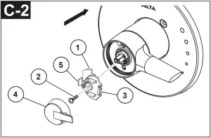
Place volume handle (11) onto cartridge. Seat stop (13) into volume handle, place adapter (14) into handle and tighten screw (15). Thread cover (12) onto handle. Place temperature handle assembly (16) onto cartridge and drive set screw (17).
Install adapter (1) over valve stem (2) and secure it with screw (3).
Install washer (4) onto handle (5), slide handle onto adapter and secure it with screw (6), then cover set screw with handle button (7).
[6] Potential scald or thermal shock injury could result due to cross flow if outlet at the shower is blocked or restricted (e.g., pause control on hand shower). Be sure to point hand shower away from you when re-starting flow or install inlet check valves on both supply lines to prevent possible injury.
Clean and Care
Care should be given to the cleaning of this product. Although its finish is extremely durable, it can be damaged by harsh abrasives or polish. To clean, simply wipe gently with a damp cloth and blot dry with a soft towel.
Warning: Scrubbing Bubbles® Bathroom Cleaner and Lysol® Basin Tub and Tile Cleaner must not be used on the clear knob handles and levers. Use of these cleaners can result in cracked or severely damaged handles. If overspray gets onto the handles, immediately wipe them dry with a soft cotton cloth.
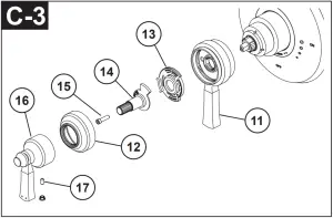
Maintenance
Faucet leaks from tub spout/hand shower:
SHUT OFF WATER SUPPLIES.
Replace valve cartridge
RP46463 or RP32104
See Helpful Hints 1, 2 & 3.
Helpful Hints:
1. Before removing valve cartridge assembly for any maintenance, be sure to note the position of the rotational limit stop on the cap. The valve cartridge assembly must always be put back in the same position. BE SAFE! After you have finished the installation, turn on valve to make sure COLD WATER FLOWS FIRST.
2. To remove valve cartridge from body, shut off water supplies and remove handle and bonnet nut. Do not pry the valve cartridge out of the body with a screwdriver. Place handle on stem and rotate counterclockwise approximately 1/4 turn after the stop has been contacted. Lift valve cartridge out of body.
Remove seats and springs and replace. Place the largest diameter of the spring into the seat pocket first and then press the tapered end of the seal over the spring. Reassemble valve cartridge and replace in body following instructions given in 1 above.
3. If the water in your area has lime, rust, sand or other contaminants in it, your pressure balance valve will require periodic inspection. The frequency of the inspection will depend on the amount of contaminants in the water. To inspect valve cartridge remove it and follow the steps in note 1 above. Turn the valve to the full mix position and shake the cartridge vigorously. If there is a rattling sound, the unit is functional and can be reinstalled following instructions given in note 1 above. If there is no rattle, replace the housing assembly with the proper RP.
Cartridge Summary Reference Sheet
Units shipped in March 2006 and after.
Units shipped before March 2006.
GENERAL SAFETY INFORMATION
READ AND SAVE THESE INSTRUCTIONS GENERAL SAFETY INFORMATION
- Make sure that the electric service supply voltage is AC
120V, 60Hz. - Follow all local electrical and safety codes, as well as
the National Electrical Code (NEC) and the Occupational Safety and Health Act (OSH Act). - Always disconnect the power source before working on or near the ventilating fan, motor or junction box.
- Protect the power cord from sharp edges, oil, grease, hot surfaces, chemicals or other objects.
- Do not kink the power cord.
- shown in Fig.A.
- Provide suction parts with proper ventilation.
- This unit is UL Listed for use over a bathtub or shower when installed in a GFCI protected branch circuit.
- These ventilating fans are intended for residential usage only.
This product is designed for ceiling installation only. Do not mount this product in a wall.
WARNING
TO REDUCE THE RISK OF FIRE, ELECTRIC SHOCK, OR INJURY TO PERSONS, OBSERVE THE FOLLOWING:
- Use this unit only in the manner intended by the manufacturer. If you have questions, contact the manufacturer.
- Before servicing or cleaning the unit, switch the power off at the service panel and lock the service disconnecting means to prevent the power from being switched on accidentally. When the service disconnecting means cannot be locked, securely fasten a prominent warning device, such as a tag, to the service panel.
- Installation work and electrical wiring must be done by a qualified person(s) in acordance with all appliccble codes and standard, including fire rated construction.
- Suffucuent air is needed for proper combustion and exburning exhausting of gases through the flue of fuel burning equipment to prevent backdrafting. Follow the heating equipment manufacturer’s guideline and safety standards such as those published by the National Fire
Protection Association (NFPA), and the American Society
for Heating Refrigeration and Air Conditioning Engineers
(ASHRAE) and local code authorities. - When cutting or drilling into the wall or ceiling, do not
damage electrical wiring and other hidden utilities. - Ducted ventilating fans must always be vented to the outdoors.
- If this unit is to be installed over a tub or shower, it must be marked as appropriate for the application and be connected to a GFCI (Ground Fault Circuit lnterrupter) protected branch circuit.
- Do not use this unit with any other solid-state control device. Solid-state controls may cause harmonic distortion, which can cause a motor humming noise.
- NEVER place a switch where it can be reached from a tub or shower.
- Not to be installed in a ceiling thermally insulated to a value greater than R50. (This is required for installation in Canada only).
Turning angle too large
Duct shrink
Too many elbows
Elbow near the body Body
Minimum 18 in.
CAUTION
- For general ventilating use only. Do not use to exhaust hazardous or explosive materials and vapors.
- Not for use in cooking areas.
- This product must properly connect to the grounding conductor of the supply circuit.
- To reduce the risk of injury to persons, install the fan at least 8.2 feet (2.5m) above the floor.
GENERAL SAFETY INFORMATION
WARNING
Changes or modifications not expressly approved by the party responsible for compliance could void the user’s authority to operate the equipment.
This device complies with part 15 of the FCC Rules. Operation is subject to the following two conditions:
- This device may not cause harmful interference, and
- This device must accept any interference received, including
interference that may cause undesired operation.
NOTE: This equipment has been tested and found to comply with the limits for a Class B digital device, pursuant to part 15 of the FCC Rules. These limits are designed to provide reasonable protection against harmful interference in a residential installation. This equipment generates, uses and can radiate radio frequency energy and, if not installed and used in accordance with the instructions, may cause harmful interference to radio communications. However, there is no guarantee that interference will not occur in a particular installation. If this equipment does cause harmful interference to radio or television reception, which can be determined by turning the equipment off and on, the user is encouraged to try to correct t he interference by one or more of the following measures:
–Reorient or relocate the receiving antenna.
–Increase the separation between the equipment and receiver.
–Connect the equipment into an outlet on a circuit different from that to which the receiver is connected.
–Consult the dealer or an experienced radio/TV technician for help.
The Bluetooth® word mark and logos are registered trademarks owned by Bluetooth SIG, Inc. and any use of such marks by Delta Electronics, Inc. is under license. Other trademarks and trade names are those of their respective owners.
The Bluetooth® speaker complies with FCC radiation exposure limits set forth for an uncontrolled environment. End users must follow the specific operating instructions for satisfying exposure compliance. This speaker must not be co-located or operate in conjuction with any other antenna or transmitter. Changes or modifications not expressly approved by the party responsible for compliance could void the user’s authority to operate this equipment.
NOTE: The Grantee is not responsible for any changes or modifications not expressly approved by the party responsible for compliance. Such modifications could void the user’s authority to operate the equipment.
PREPARATION
Tools Required for Assembly (not included): Hammer, Flathead Screwdriver, Wire Nuts, Nails, Duct Tape, Phillips Head Screwdriver, Utility Knife Helpful Tools (not included): Electric Drill, Drill Bits
WARNING:
Turn off electricity at breaker box before beginning installation.
- Carefully remove unit from carton.
- Check area above installation location to be sure that wiring can run to the planned location and that duct
proper ventilation. - Inspect duct work and wiring before proceeding with installation.
- Before installation, provide inspection and future maintenance access at a location that will not interfere with installation work.
- You may need the help of a second person to install this fan: one person on the attic side and one on the room side.
Note: Installations may vary depending on how the previous bath fan was installed. Supplies necessary for the installation of your bath fan are not all included. However, most are available at your local home improvement or hardware store.
DIMENSION REQUIREMENTS
Housing Dimension (L)
7 1/2 in.
Housing Dimension (W)
7 1/4 in.
Housing Dimension (H)
5 3/4 in.
WIRING DIAGRAM
BLUE GROUND (bare)
ON/OFF SWITCH (purchase separately)
SWITCH BOX
BLACK WHITE
SPEAKER FAN SWITCH SWITCH
120 VAC LINE IN
WIRING PLATE WIRE NUT (NOT INCLUDED)
Short piece of flexible duct helps alignment and absorbs sound
Fan housing
Roof cap (with built-in damper)
or
Seal gap around housing
Caulk termination to duct
Wall cap (with built-in damper)
Proper insulation around the fan to minimize building heat loss and gain. 4″ circular duct is recommended for installation. The ducting from this fan to the outside of building has a strong effect on the air flow, noise and energy use of the fan. Use the shortest, straightest duct routing possible for best performance, and avoid installing the fan with smaller ducts than recommended. Insulation around the ducts can reduce energy loss and inhibit mold growth. Fans installed with existing ducts may not achieve their rated air flow.
The fan will operate most efficiently when located where the shortest possible duct run and minimum number of elbows will be needed. Use a roof cap or wall cap that has a built-in damper to reduce backdrafts.
JUNCTION BOX
BLACK WHITE
BLUE WHITE GREEN
SWITCH BOX
OFF
ON
L
FAN SWITCH
N
OFF
ON
L
SPEAKER SWITCH
N
GRD
5
ASSEMBLY INSTRUCTIONS
NEW CONSTRUCTION BEFORE INSTALLATION
1
3
Turn off power source. Review all safety precautions.
1
1. Attach the duct connector 3 to the fan housing 1 .
2
2. Remove the wiring box cover from the fan
1
housing 1 . Remove the wiring knockout from
the wiring box cover with a flathead screwdriver
(not included).
3. Place the fan housing 1 next to a ceiling joist or wall stud, The fan housing 1 should be level and perpendicular to the joist or stud.
4. Mount the fan housing 1 to the joist or stud using nails (not included) where indicated.
3
1
4
1
Joist or wall stud
Joist or wall stud
5. Pull the wire through the hole and into the junction
5
box (not included), secure 120VAC house wiring
from the wall switch to the fan as shown in the
wiring diagram on page5. 14AWG is the smallest
conductor that shall be used for branch-circuit
wiring.
Push the wires back through the hole. Reattach the wiring box cover.
6
ASSEMBLY INSTRUCTIONS
6. Install a circular 4 in. duct (not included) and secure it with duct tape or clamps (neither included). Finish ceiling work. The ceiling hole should be aligned with the edge of the fan housing.
7. Plug the Micro USB connector into the speaker assembly 4 , and secure the speaker assembly to the holder on the fan unit.
8. Pinch the mounting springs on the grille 2 , and insert them into the narrow rectangular slots inside the fan. Push the grille up toward the ceiling. Turn on electricity at the breaker box after finishing installation.
6
4 in. duct
Duct tape or clamp
7
4
8
2
Ceiling
EXISTING CONSTRUCTION
1
BEFORE INSTALLATION Turn off power source. Review all safety precautions. 1. Remove existing fan.
2. Measure the opening to ensure it is large enough
2
to accommodate the new fan body (7 1/2 in. x 7 1/4 in.).
Note: 7 1/4 inch side of opening should be flush with the joist.
7
ASSEMBLY INSTRUCTIONS
3 3. If this fan is not replacing an old fan, be sure to cut
a 7 1/2 in. x 7 1/4 in. opening for the fan housing 1 . Make sure the 7 1/4 inch side of opening is flush with the joist for installation from below.
4 4. Attach the duct connector 3 to the fan housing 1 .
1
5. Remove the three screws that hold the fan motor assembly in place. Remove the fan motor assembly from the fan housing 1 . Unplug fan and speaker connector.
5
1
6. Pull the wire through the hole and into the junction box
6
(not included), secure 120VAC house wiring from the
wall switch to the fan as shown in the wiring diagram
on page5. 14AWG is the smallest conductor that shall
be used for branch-circuit wiring.
Push the wires back through the hole. Reattach the
wiring box cover.
7 7. Install a circular 4 in. duct (not included) and secure
it with duct tape or clamps (neither included).
7 1/49.4in” .
791.4/”2 in. 3
FAN CONNECTOR SPEAKER CONNECTOR
a
8 8. Insert the fan housing 1 through the existing hole
in the ceiling. The fan housing 1 should be level
1
and perpendicular to the joist or stud.
8
ASSEMBLY INSTRUCTIONS
9. Mount the fan housing 1 to the joist or stud using nails (not included) where indicated by arrows inside the fan housing 1 .
9
1
Joist or wall stud
10. Plug the fan assembly back into the fan housing 1 .Reattach the fan assembly using the thress screws removed in step 5.
Nail
10
1
11. Plug the Micro USB connector into the speaker
11
assembly 4 , and secure the speaker assembly
to the holder on the fan unit.
4
4 inch duct Tape
FAN CONNECTOR SPEAKER CONNECTOR
9
ASSEMBLY INSTRUCTIONS
12. Pinch the mounting springs on the grille 2 , and
12
insert them into the narrow rectangular slots inside th.e fan. Push the grille up toward the ceiling.
Turn on electricity at the breaker box after finishing installation.
2
OPERATION
Fan Mode: Turn the Fan switch to operate ON/OFF.
Speaker Mode: Turn the Speaker switch to operate ON/OFF.
Pairing your Bluetooth device to the speaker for the first time
1. To play your personal music or audio files, you need a Bluetooth device, like smart phone, tablet, or any other such devices.
2. Place the Bluetooth device located within 10 meters of the fan.
3. Set your device to midrange volume before connecting to the speaker.
4. Turn ON the Speaker switch, the blue LED indicator flashes in pairing mode.
5. Follow the instructions that came with your Bluetooth device to make it discoverable or to set it to search for other Bluetooth accessories. This may involve entering a passkey or PIN( Personal Identification Number).
6. From the home screen, tap Settings > Bluetooth, the device searches and a list of discoverable devices will appear, choose “DeltaBreez ITG”, and enter a passkey or PIN (0000) if prompted.
7. When pairing is completed, the blue LED indicator will solid on, you can use the Bluetooth speaker to play music or audio files with your device.
10
CARE AND MAINTENANCE
See safety information before proceeding. Routine maintenance should be done at least once a year.
· Never use solvents, thinner or harsh chemicals when cleaning the fan.
· Do not allow water to enter the motor.
1
· Do not immerse metal parts in water.
· Do not immerse resin parts in water over 140º Fahrenheit.
· Do not immerse Bluetooth speaker in water.
Turn off power source. Review all safety precautions.
2
1. To remove grille , squeeze springs and pull down. 2
2. Wash and clean the grille in a sink and dry with a cloth.
2
2
3. Remove dust and dirt from the fan housing with a
3
vacuum cleaner.
1
4. Dampen cloth with dust detergent and wipe the fan
4
housing . Then wipe dry with a clean cloth.
Vacuum cleaner
5. Replace grille back onto fan housing 6. Turn on power source to operate fan again.
1
5
1
2
11
TROUBLESHOOTING
PROBLEM
POSSIBLE CAUSE
CORRECTIVE ACTION
The fan is not turning on
1. Power off 2. Faulty switch 3. Faulty wire connection
1. Make sure power supply is on. 2. Test or replace switch. 3. Check wire in switch box.
The fan seems louder than it should
1. CFM too great
2. Damper not working properly or damaged
3. Bend in duct too close to fan discharge
4. Fan discharge
duct 5. Fan body not securely
attached
1. Be sure the CFM rating on the fan matches the size of your room.
2. Check damper to ensure it is opening and closing properly. If the damper has become damaged, please call Customer Service.
3. Be sure you do not have any sharp bends in duct closer than 18 in. to the fan discharge.
4. Use recommended size ducting to reduce fan noise.
5. Be sure the fan is securely attached to your ceiling joists.
The fan is not clearing the room
1. airfow within room
1. Be sure a door or window is slightly ajar or opened
2.
2. Be sure the CFM rating on the fan matches the
requirements for your room size.
12
DIMENSIONS
4
9 3/8
UNIT: INCH
10 3/4
3/4
5 3/4
PRODUCT SPECIFICATIONS
Model No.
Air Flow Power
Voltage Frequency @0.1″SP @ 0.1″SP
(V)
(Hz)
(CFM) (W)
Max Current (Amps)
Weight (lb.)
Note
70BT / VFB070B4BT1 120
60
70
8.4
0.22
6.7 Bluetooth
Speaker
Note: Design and specifications subject to change without notice.
13
WARRANTY
DELTA ELECTRONICS THREE YEAR LIMITED WARRANTY Delta Electronics Inc. (“Delta Electronics”) warrants to the original consumer purchaser in the USA and Canada that the Breez ventilation fan products will be free from defects in material or workmanship. This warranty is limited to three (3) years from the original date of purchase. Limitations and Exclusions 1. During the warranty period, a replacement for any defective product will be supplied free of charge for installation
by the consumer. The warranty provided herein does not cover charges for labor or other costs incurred in the troubleshooting, repair, removal, and installation service. 2. All returns of defective parts or products must include the product model number, and must be made through an authorized Delta Electronics distributor. Authorized returns must be shipped prepaid. Repaired or replacement products will be shipped by Delta Electronics F.O.B. shipping point. 3. Delta Electronics shall not be liable for any indirect, incidental, consequential, punitive, or special damages arising out of or in connection with products use or performance, regardless of the form of action whether in contract, tort (including negligence), strict product liability or otherwise. 4. 5. The warranty does not cover if user does not comply with manufacturer’s installation manual. 6. To qualify for warranty service, you must notify Delta Electronics at the address or telephone number below. 7. Delta Electronics shall have no liability to the original owner-user with respect to any defect caused by abuse, misuse, neglect, improper transportation or storage, improper testing, improper installation, improper operation, accident of products or parts thereof, or unusual deterioration or degradation of products or parts thereof due to
Address: 46101 Fremont Boulevard, Fremont, CA 94538 US Toll Free Number: 1-888-979-9889 www.deltabreez.com
14
![]()
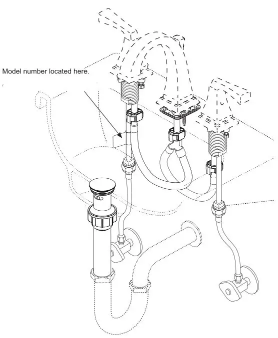
Image is for reference only.
Register Online
www.deltafaucet.com/registerme
To reference replacement parts and access additional technical documents and product info, visit www.deltafaucet.com
1-800-345-3358
[email protected]
Read all instructions prior to installation.
 CAUTION
Failure to read these instructions prior to installation may result in personal injury, property damage, or product failure. Manufacturer assumes no responsibility for product failure due to improper installation.
You may need:
Cleaning and Care
Care should be given to the cleaning of this product. Although its finish is extremely durable, it can be damaged by harsh abrasives or polish. To clean, simply wipe gently with a damp cloth and blot dry with a soft towel.
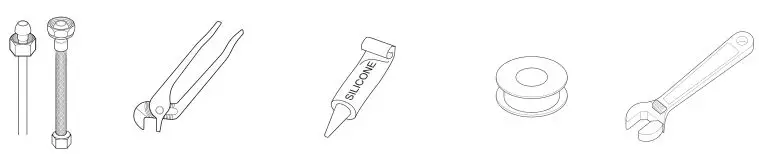
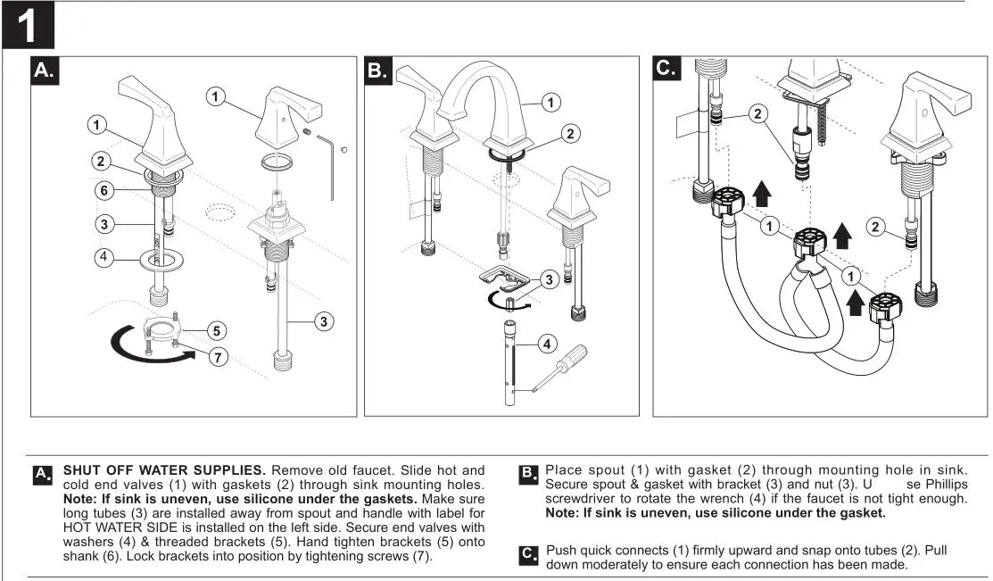
CONNECT TO WATER SUPPLIES.
(HOOK-UPS NOT PROVIDED).
Turn on hot and cold water supplies and flush water lines into a container for one minute. Important: This flushes away any debris that could cause damage to internal parts.
Choose hook-ups for 1/2″ I.P.S. connections: (1) Ball nose riser (3/8″ O.D. copper tubing), or (2) 1/2″ I.P.S. faucet connector. Use coupling nuts (3) (not supplied) with the ball nose risers (1). Use two wrenches when tightening. Do not overtighten.
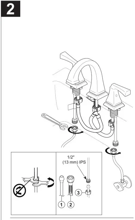
Install Pop-Up Assembly
A. Remove head (1) and nut, washer, black seal (2) from body (3).
B. Apply silicone sealant to underside of flange (1). Insert body (2) into sink.
C. Apply silicone grease to the inside diameter of the black seal (1) and threads on body (2) and assemble. Install nut (3) and hand tighten to the sink. Insert head (4) into body.
D. Connect assembly to drain (1).
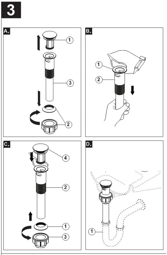
Plastic Pop-Up
A. Remove stopper (1) and flange (2). Screw nut (3) all the way down. Push black gasket (4) down.
B. Apply silicone to underside of flange (1). Insert body (2) into sink. Screw flange onto body. Pivot hole (3) must face back of sink. Pull assembly down firmly and hold in place. DO NOT TWIST. Tighten nut (4), remove excess sealant .
C. Remove pivot nut (1). Install horizontal rod (2) and stopper (3) as removable (4) or non-removable (5). Hand tighten nut (1). Gaskets (6) only required if supplied .
D. Attach horizontal rod (1) to strap (2) using clip (3). Install lift rod (4), tighten screw (5). Connect assembly to drain (6) .
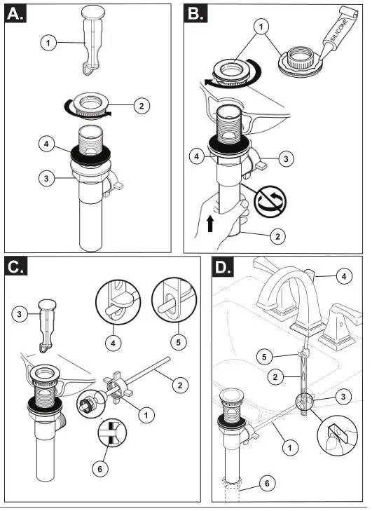
FLUSH SYSTEM/CHECK FOR LEAKS.
Remove aerator (1) using supplied wrench (2) or coin and turn faucet handles (3) to the full on mixed position. Turn on hot and cold water supplies (4) and flush water lines for one minute.
Important: This flushes away any debris that could cause damage to internal parts.
Check all connections at arrows for leaks. Re-tighten if necessary, but do not overtighten. Replace aerator.
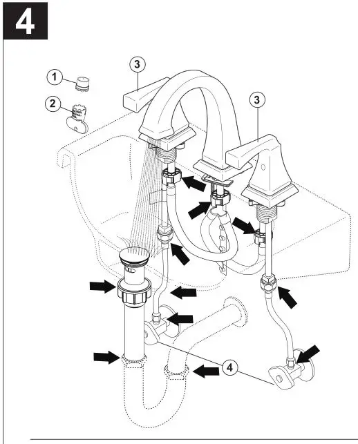
Maintenance
SHUT OFF WATER SUPPLIES
NOTE: Remove handles by hand turning handle base counterclockwise.
If faucet exhibits very low flow:
Replace Stem Unit Assembly (1) and Seats and Springs (2)*.
If faucet exhibits very low flow:
A. Remove and clean Aerator (3), or
B. Clean Seats and Springs (2) of any debris.
*Install stems (1) correctly for proper handle rotation:
Note:
1. The stops (4) must point to the center of the faucet for proper handle rotation.
2. Replace handle properly. Be sure the handle with “H” mark (5) to be installed onto the left and the handle with “C” mark onto the right.
Limited Warranty on Delta ® Faucets
Parts and Finish. All parts (other than electronic parts and batteries) and finishes of Delta ® faucets purchased from authorized Delta sellers are warranted to the original consumer purchaser to be free from defects in material and workmanship for as long as the original consumer purchaser owns the home in which the faucet was first installed. For commercial purchasers, (a) the warranty period is ten (10) years for multi-family residential applications and (b) five (5) years for all other commercial applications, in each case from the date of original purchase. For purposes of this warranty, the term “multi-family residential application” refers to the purchase of the faucet from an authorized Delta seller by a purchaser who owns but does not live in the residential dwelling in which the faucet is initially installed, such as in a rented or leased single unit or multi-unit detached home (duplex or townhome), or a condominium, apartment building or community living center. The following installations are not considered multi-family residential applications, are excluded from the 10-year warranty and are subject to the 5-year warranty: industrial, institutional or other business premises, such as a dormitory, hospitality premises (hotel, motel or extended stay location), airport, educational facility, long- or short-term healthcare facility (hospital, rehabilitation center, nursing, assisted or staged-care living unit), public space or common area.
Parts and Finish for Delta ® Recertified Faucets. Delta Faucet Company offers for sale on deltafaucet.com Delta ® Recertified faucets. All parts (other than electronic parts and batteries) and finishes of these Delta ® Recertified faucets are warranted to the original consumer purchaser to be free from defects in material and workmanship for ten (10) years from the date of original purchase. For commercial purchasers, the warranty period is one (1) year from the date of original purchase.
Electronic Parts. Electronic parts (other than batteries), if any, of Delta ® faucets purchased from deltafaucet.com or authorized Delta sellers are warranted to the original consumer purchaser to be free from defects in material and workmanship for five (5) years from the date of original purchase or, for commercial purchasers, for one (1) year from the date of original purchase. No warranty is provided on batteries.
What We Will Do. Delta Faucet Company will repair or replace, free of charge, during the applicable warranty period (as described above), any part or finish that proves defective in material and/or workmanship under normal installation, use and service. If repair or replacement is not practical, Delta Faucet Company may elect to refund the purchase price in exchange for the return of the product. These are your exclusive remedies.
What Is Not Covered. Because Delta Faucet Company is unable to control the quality of Delta products sold by unauthorized sellers, unless otherwise prohibited by law, this warranty does not cover Delta products purchased from unauthorized sellers.
Any labor charges incurred by the purchaser to repair, replace, install or remove this product are not covered by this warranty. Delta Faucet Company shall not be liable for any damage to the faucet resulting from reasonable wear and tear, outdoor use, misuse (including use of the product for an unintended application), freezing water, abuse, neglect or improper or incorrectly performed installation, maintenance or repair, including failure to follow the applicable care and cleaning instructions. Delta Faucet Company recommends using a professional plumber for all installation and repair of faucets. We also recommend that you use only genuine Delta ® replacement parts.
What You Must Do To Obtain Warranty Service or Replacement Parts. A warranty claim may be made and replacement parts may be obtained by calling 1 800 345 DELTA (3358) or by contacting us by mail or online as follows (please include your model number and date of original purchase):
In the United States and Mexico:
Delta Faucet Company
Product Service
55 E. 111th Street
Indianapolis, IN 46280
Attention: Customer Solutions
www.deltafaucet.com/service-parts/contact-us
In Canada:
Masco Canada Limited, Plumbing Group
Technical Service Centre
350 South Edgeware Road
St. Thomas, Ontario, Canada N5P 4L1
Attention: Customer Service
http://www.deltafaucet.ca/customersupport/assistance.html
Proof of purchase (original sales receipt) from the original purchaser must be made available to Delta Faucet Company for all warranty claims unless the purchaser has registered the product with Delta Faucet Company or the product is a Delta ® Recertified product purchased from deltafaucet.com. This warranty applies only to Delta ® faucets manufactured after January 1, 2019 and installed in the United States of America, Canada and Mexico.
Limitation on Duration of Implied Warranties. Please note that some states/provinces (including Quebec) do not allow limitations on how long an implied warranty lasts, so the below limitations may not apply to you. TO THE MAXIMUM EXTENT PERMITTED BY APPLICABLE LAW, ANY IMPLIED WARRANTY, INCLUDING THE IMPLIED WARRANTIES OF MERCHANTABILITY AND OF FITNESS FOR A PARTICULAR PURPOSE, IS LIMITED TO THE STATUTORY PERIOD OR THE DURATION OF THIS WARRANTY, WHICHEVER IS SHORTER.
Limitation of Special, Incidental or Consequential Damages. Please note that some states/provinces (including Quebec) do not allow the exclusion or limitation of special, incidental or consequential damages, so the below limitations and exclusions may not apply to you. TO THE MAXIMUM EXTENT PERMITTED BY APPLICABLE LAW, THIS WARRANTY DOES NOT COVER, AND DELTA FAUCET COMPANY SHALL NOT BE LIABLE FOR, ANY SPECIAL, INCIDENTAL OR CONSEQUENTIAL DAMAGES (INCLUDING LABOR CHARGES TO REPAIR, REPLACE, INSTALL OR REMOVE THIS PRODUCT), WHETHER ARISING OUT OF BREACH OF ANY EXPRESS OR IMPLIED WARRANTY, BREACH OF CONTRACT, TORT, OR OTHERWISE. DELTA FAUCET COMPANY SHALL NOT BE LIABLE FOR ANY DAMAGE TO THE FAUCET RESULTING FROM REASONABLE WEAR AND TEAR, OUTDOOR USE, MISUSE (INCLUDING USE OF THE PRODUCT FOR AN UNINTENDED APPLICATION), FREEZING WATER, ABUSE, NEGLECT OR IMPROPER OR INCORRECTLY PERFORMED INSTALLATION, MAINTENANCE OR REPAIR, INCLUDING FAILURE TO FOLLOW THE APPLICABLE INSTALLATION, CARE AND CLEANING INSTRUCTIONS. Notice to residents of the State of New Jersey: The provisions of this warranty, including its limitations, are intended to apply to the fullest extent permitted by the laws of the State of New Jersey.
Additional Rights. This warranty gives you specific legal rights, and you may also have other rights which vary from state/province to state/province.
This is Delta Faucet Company’s exclusive written warranty and the warranty is not transferable.
If you have any questions or concerns regarding our warranty, please contact us as provided above or view our Warranty FAQs at www.deltafaucet.com.
© 2020 Delta Faucet Company
]]>