D-Link DWR-932 4G-LTE Mobile Router Installation

CONTENTS OF PACKAGING
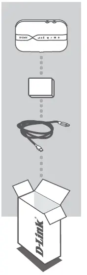
CONTENTS
- 4G/LTE MOBILE ROUTER DWR-932
- RECHARGEABLE BATTERY
- USB CABLE USB TYPE A TO MICRO USB TYPE B
- If any of these items are missing or damaged, please contact your reseller.
SYSTEM REQUIREMENTS
- A 4G SIM/UICC card.
- Computer with:
- Microsoft Windows® 10/8/7, or Mac with OS X 10.5 or higher
- 500 MHz processor or above and at least 128 MB RAM
- Internet Explorer 9 or Chrome 25 or higher with JavaScript installed and enabled
HARDWARE SETUP
QUICK INSTALLATION
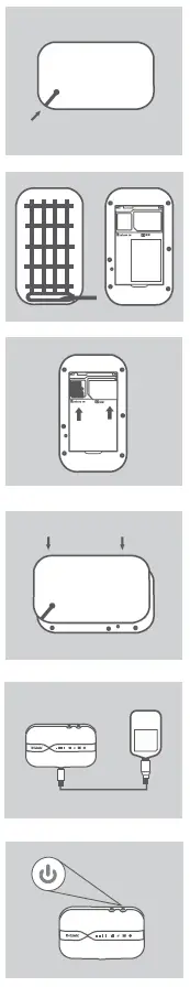
- Remove the battery cover on the back of the device by gently prying it up from the case using the corner notch, then remove the battery.
- Note the SSID (network name) and password on the label on the battery cover. If you want to connect to the DWR-932 wirelessly, you will need to enter this SSID and password.
- Slide the SIM card frame to the right and lift up. Insert the SIM/UICC card into the SIM/UICC card slot as shown, ensuring the gold contacts are facing down. Replace the frame and slide it left to lock it in position.
Note: Install a MicroSD card at this time (optional) - Reinsert the battery and replace the battery cover.
- Connect the Micro USB end of the USB cable to the Micro USB port on the bottom of the DWR-932 and plug the USB end into the USB port of a power adapter (not included) or a PC to charge the battery.
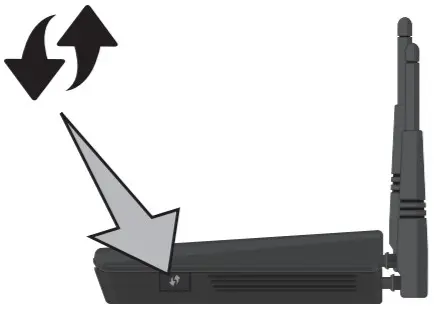
- Press and hold the power button for three seconds to turn on the device. Once the power LED changes from green to solid blue or amber, you may proceed with configuration.
ROUTER MODE
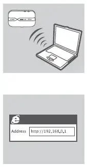
- Use your PC’s wireless adapter to connect to the dlink_DWR-932_xxxx wireless network. The wireless network name (SSID) and password are printed on the label on the battery cover.
- Use a web browser to go to 192.168.0.1 to log in to the router’s configuration interface. The default username is admin, and the password should be left blank.
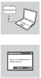
4G USB MODEM MODE
- Connect the DWR-932 to your PC using the USB cable. Follow any on-screen driver prompts.
- Use a web browser to 192.168.0.1 to log in to DWR-932’s configuration interface. The default username is admin, and the default password should be left blank
TROUBLESHOOTING
SETUP AND CONFIGURATION PROBLEMS
- WHY AM I UNABLE TO CONNECT TO MY MOBILE INTERNET SERVICE?
- Check to make sure the SIM card is installed properly, and that your SIM card has 4G/3G data service. Also, make sure that antivirus software is not blocking your connection and you are not connected to other Internet sources.
- Open Windows Explorer and double click on the storage drive for the DWR-932.
- HOW DO I CONFIGURE MY DWR-932 ROUTER OR CHECK MY WIRELESS NETWORK NAME (SSID) AND WIRELESS ENCRYPTION KEY?
- Power on the DWR-932 and connect it to your PC using the supplied Micro- USB cable.
- Open a web browser and enter the router’s IP address: http://192.168.0.1
- Log into the router using the default username admin, leave the password field blank.
- Once logged in, you can use the wizard to view the wireless network name and password of your router or make changes manually.
Note: If you have changed the password and cannot remember it, you will need to reset the router to factory defaults.
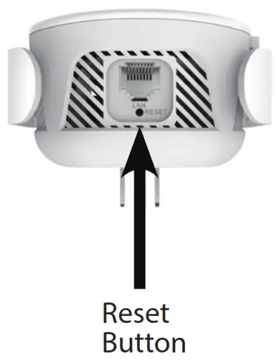
- HOW DO I RESET MY DWR-932 TO FACTORY DEFAULT SETTINGS?
If you cannot remember your router’s administrator password or wireless network settings, you may reset the DWR-932 to default settings by removing the battery cover and using an implement such as a straightened paperclip to press and hold the reset button on the router for 5 seconds.
Note: Resetting the router to factory default will erase the current configuration settings.
Quick Installation Guide Nuclias Cloud-Managed Wave 2 Outdoor Access Point / Guide
This document will guide you through the basic installation process for your new D-Link Nuclias Cloud-Managed Access Point. / Ce document vous guidera tout au long de la procédure
d’installation de votre nouveau point d’accès D-Link Nuclias Cloud-Managed
About This Guide
This installation guide provides basic instructions for installing the DBA-3620P Nuclias Cloud- Managed Wave 2 Outdoor Access Point on your network. For additional information about how
to use the Access Point, please see the User Manual, which is available on the D-Link support website.
Before You Begin
This installation guide provides instructions for installing the DBA-3620P on your network. Additional documentation is also available on the D-Link support website.
- D-Link Nuclias User Manual: For additional information and instructions on how to configure the device using D-Link Nuclias Cloud.
System Requirements
- Windows®, Macintosh®, or Linux-based operating system
- Ethernet port or installed Ethernet adapter
- Internet Explorer 11, Safari 7, Firefox 28, Google Chrome 33 or higher
Unpacking the Product
Open the shipping carton and carefully unpack its contents. Please consult the packing list below to make sure all items are present and undamaged. If any item is missing or damaged, please contact
your local D-Link reseller for a replacement.
- DBA-3620P Nuclias Cloud-Managed Wave 2 Outdoor Access Point
- Shielded Cat 5E Ethernet Cable
- Mounting Ties (Qty. 2)
- Wall Mount Base
- Console Cable
- Grounding Wire
Note: To power the DBA-3620P, please use any D-Link IEEE 802.3at/af-compliant PoE switch or the D-Link DPE-311GI PoE injector.
Optional Accessories
– PoE Injector (Model: DPE:311GI)
Note: These accessories are not included in the package. If any of these items are required, please contact your reseller to order it.
Hardware Overview
LEDs
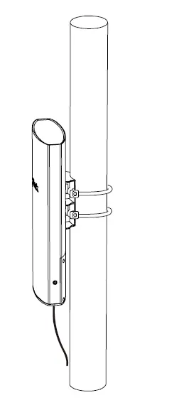
Figure 1. DBA-3620P LEDs
LED |
Status |
Description |
| Power/ Cloud | Solid Orange | Device is performing startup procedure |
| Blinking
Orange |
Device is resetting to
its default settings or it is upgrading its firmware |
|
| Solid Green | Device is currently in
cloud mode |
|
| Blinking Green | Device is trying to connect to D-Link Nuclias Cloud | |
| Solid Red | Device is not working
properly in cloud mode |
|
| LAN
(PoE in) |
Solid Green | Link Present |
| Blinking Green | Sending or receiving data packets | |
| Light Off | Link down or
unplugged |
|
| WLAN (2.4GHz
/5 GHz) |
Solid Green | Device Ready |
| Blinking Green | Sending or receiving packets | |
| Light Off | Radio off/ device is
undergoing boot process |
Interfaces
Figure 2. DBA-3620P Rear Panel
* DBA-3620P can be powered via PoE from LAN (PoE)
** A manual reboot is needed when switching from internal to external antennas, and vice versa.
*** (Optional) RP-SMA connectors for external 2.4/5 GHz dual-band antennas.
*** For external antennas, the toggle switch must be switched to EXT ANT
Configuring the Access Point
Using D-Link Nuclias
Note: To use D-Link Nuclias, the DBA-3620P must be connected to the Internet.
The DBA-3620P is designed to be managed through
D-Link Nuclias Cloud. Refer to the D-Link Nuclias User Manual for detailed configuration instructions.
Figure 3: Connecting through D-Link Nuclias
- On an Internet-connected PC, open a web browser and go to www.nuclias.com.
- Enter your D-Link Nuclias user name and password.
Manual Configuration
Note: D-Link recommends manually configuring the device before mounting it. If you are unable to connect to D-Link Nuclias Cloud,
you may need to manually configure the DBA-3620P using its web user interface (UI). Refer to the D-Link
NucliasUser Manual for detailed configuration instructions. Use one of the following methods to access the web user interface:
Connecting through Ethernet
Note: The management PC must be in the same subnet as the DBA-3620P.
- Use an Ethernet cable to connect the DBA-3620P to the management PC or to the switch or router the management PC is connected to.
- Open a web browser and type in the default host name of the DBA-3620P and press Enter. The default host name is DBA-3620P-XXXX where XXXX represents the last 4 characters of the MAC address listed on the device label located on the bottom of the device.
- When prompted, enter the default login credentials: User name: admin Password: admin
Connecting Wirelessly
- Connect the management PC to the default SSID of the DBA-3620P. The SSID will be in the format DBA-3620PXXX where XXXX represents the last 4 characters of the MAC address listed on
the device label located on the bottom of the device. - Open a web browser and type in the default host name of the DBA-3620P and press Ent e r . The default host name is DBA-3620PXXXX where XXXX represents the last 4 characters of the MAC address listed on the device label located on the bottom of the device.
- When prompted, enter the default login credentials: User name: admin Password: admin
Installation
Figure 4. Deployment Example
Configure the access point
To set up and manage the DBA-3620P, use one of the following methods:
- LAN on DBA-3620P to Ethernet Port labeled POE on PoE Adapter
- Connect the Power Cord to the PoE Adapter and a power outlet
- Connect Computer to Ethernet Port labeled LAN on PoE Adapter
- Manage the access point from the computer: Connect the access point and your computer directly via a straight-through Ethernet cable.
- Manage the access point from the computer via the Switch or Router: Connect the access point and your computer to the same switch or router
Mounting Options
Pole Mount and Wall Mount are the two mounting options for the DBA-3620P.
Cable Requirement
Use a Cat 5 cable with an even sheath. The Ethernet ports on the DBA-3620P access point cannot accept a Cat 5 cable that has an uneven sheath; the RJ-45 connector on the cable will not fit
properly into the receptacle on the access point
Pole Mounting Installation
Installation
- Open the bottom panel with a Phillips screwdriver.
- Plug one end of Cat 5 cable into the LAN port on the DBA-3620P, and the other end to the port labeled POE on the PoE Adapter.
- Choose a gasket (6 mm or 4 mm) to fit the Ethernet cable; if CONSOLE is not in-use, please put on the black gasket.
- Close the bottom panel with a Phillips screwdriver.
- Attach a grounding wire. Instructions for the installation of that conductor to building earth by a SKILLED PERSON.
- Attach access point to a pole
- Fasten the mounting ties.
Wall Mounting Installation
Installation
- Use the supplied screws to attach the Wall Mount Base to the wall.
- Attach DBA-3620P to the Wall Mount Base. Thread and fasten the Mounting Ties.
Product Highlights
Wireless AC and Gigabit Ethernet
Get up to speed with Gigabit broadband for high-bandwidth applications such as HD and 4K video streaming anywhere in your home.
Dual-band Wi-Fi for Seamless Performance Two concurrent wireless networks for higher bandwidth, improved range, and backward compatibility.
Simple Setup
Get step-by-step setup instructions using the free mobile app to quickly set up your router and simply press the WPS button for hassle-free connections.
 DIR-853
AC1300 MU-MIMO Wi-Fi Gigabit Router
Features
Connectivity
- 802.11ac wireless specification delivers blazing-fast wireless connectivity with increased range and reliability
- 10/100/1000 Gigabit Ethernet WAN port for fast-paced Internet access
- Four 10/100/1000 Gigabit Ethernet LAN ports give you high-speed wired connectivity
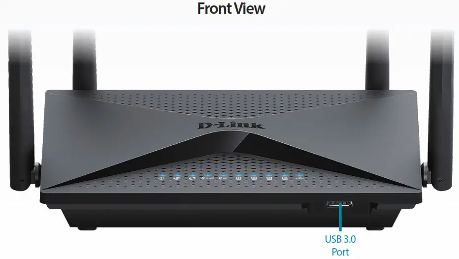
- One SuperSpeed USB 3.0 port to share media from a storage device Flexible Bandwidth
- Concurrent dual-band wireless for connections up to 1300 Mbps 1
- QoS engine to prioritize important traffic and deliver uninterrupted bandwidth Setup and Management
- Web browser-based setup and configuration
- Intuitive setup wizard to guide you through the configuration process
- Firewall and access control options to help prevent attacks and restrict access to your network
The DIR-853 AC1300 MU-MIMO Wi-Fi Gigabit Router is a powerful wireless networking solution designed for small office/home office (SOHO) environments. By combining high-speed 802.11ac Wi-Fi with dual-band technology and Gigabit Ethernet ports, the DIR-853 provides a seamless networking experience with a high degree of convenience and flexibility for SOHOs. With their easy setup and management options, these features provide a fast and easy networking solution for your home or small office.
High-Speed Wired and Wireless Connectivity
The DIR-853 upgrades your network to dual-band high-speed wireless technology to bring you lightning-fast Wi-Fi speeds of up to 1300 Mbps 1 so you can meet the increasing demand from multimedia applications. Enjoy seamless high-definition streaming media, Internet phone calls, online gaming, and content-rich web surfing throughout your home or office, even over wireless. In addition, 10/100/1000 Gigabit Ethernet ports give you solid, dependable wired performance for devices such as Network Attached Storage (NAS), media centers, and gaming consoles. The built-in Quality of Service (QoS) engine allows you to prioritize important traffic to ensure that your favorite applications are receiving optimal bandwidth.
Smooth Streaming with Wireless 802.11acWave II
The DIR-853 AC1300 MU-MIMO Wi-Fi Gigabit Router brings a host of new technologies to create the best wireless networking experience to date. Featuring support for the 802.11ac Wave II technology, the DIR-853 provides Gigabit wireless connectivity with combined transfer rates of up to 1300 Mbps 1 (867 Mbps Wireless AC + 400 Mbps Wireless N). Featuring a 2×2 + 2×2 MU-MIMO antenna configuration, the DIR-853 offers better data rates, fewer dead-spots, more coverage, and increased reliability.
![]()
DIR-853 AC1300 MU-MIMO Wi-Fi Gigabit Router
Hassle-Free D-Link Smart Connect Technology
Ever since the introduction of 5 GHz wireless technology, users have had to blindly guess whether the 5 GHz or 2.4 GHz band would provide them with the best networking experience. D-Link’s Smart Connect Technology eliminates this confusion by automatically switching devices to the optimal band. Simply initiate a connection to the DIR-853 and its advanced algorithms will determine the best network for your device to connect to, ensuring a faster, more reliable, and hassle-free experience for your colleagues, friends, and family.
Easy to Set Up and Manage
Sharing your Internet connection doesn’t have to be a complicated process; just download the free D-Link Wi-Fi app for your mobile device and follow the on-screen step-by-step instructions to set up your DIR-853. You also have the option to use a web browser to access the setup wizard and manage your router. Support for industry-standard Wi-Fi Protected Setup (WPS) lets you create encrypted connections to new devices by pressing a button. In addition, access control features allow you to restrict access to your network giving you greater control over network users.
File Sharing Right at Your Fingertips
The DIR-853 lets you connect a USB storage device and instantly share documents, movies, pictures, and music. Put your music library on a USB drive and share it with your entire home. Show photos on the living room TV while your family watches a movie on their computer. Support for UPnP and DLNA protocols lets you discover network devices so you can stream media to multiple devices easily, or save them to your device for offline playback. The intuitive interface lets anyone immediately connect to a variety of entertainment options stored on your own storage device.
Designed for Optimal Wireless Coverage
The DIR-853 antennas have been carefully placed to minimize dead zones in any environment. Smart Beam technology expands wireless range and speed, so you’ll be able to enjoy faster speeds in the farthest corners of your home. Furthermore, because of the design of the placement of internal antennas, you can rest assured that the AC1300 MU-MIMO Wi-Fi Gigabit Router will achieve the best possible performance no matter where you place it.

Technical Specifications
| General | ||
| Device Interfaces | • IEEE 802.11 ac/n/g/b/a wireless LAN • 10/100/1000 Gigabit Ethernet WAN port |
• Four 10/100/1000 Gigabit Ethernet LAN ports • One SuperSpeed USB 3.0 port |
| LEDs | • Power • Internet • WPS • 2.4 GHz WLAN |
• 5 GHz WLAN • LAN (1-4) • USB 3.0 |
| Antenna Type | • Four external antennas | |
| Wi-Fi Data Rate | • 2.4 GHz • Up to 444 Mbps1 |
• 5 GHz • Up to 866 Mbps1 |
| Standards | • IEEE 802.11ac • IEEE 802.11n • IEEE 802.11g • IEEE 802.3ab |
• IEEE 802.11b • IEEE 802.11a • IEEE 802.11d • IEEE 802.3u |
| Minimum Requirements | • Windows 10/8.1/8/7/Vista or MAC OS X 10.6 or higher • Internet Explorer 10, Firefox 28.0, Chrome 28.0, Safari 6.0, or another Javascript browser |
• Network Interface Card • Cable/DSL modem or other Internet service provider equipment with Ethernet port |
| Functionality | ||
| Security | • WPA & WPA2 (Wi-Fi Protected Access) | • WPS (Wi-Fi Protected Setup) |
| Advanced Features | • Web setup wizard • QoS (Quality of Service) • DMZ (De-militarized Zone) |
• Firewall – Network Address Translation (NAT) • Guest Zone • IPv6-Ready |
| Physical | ||
| Dimensions | • 203.97 x 137.98 x 43.38 mm (8.03 x 5.43 x 1.7 in) | |
| Weight | • 349 g ( 0.76 lbs) | |
| Power Adaptor | • Input: 100 to 240 V AC, 50/60 Hz | • Output: 12 V, 1.5 A |
| Temperature | • Operating: 0 to 40 °C (32 to 104 °F) | • Storage: -20 to 65 °C (-4 to 149 °F) |
| Humidity | • Operating: 10% to 90% non-condensing | • Storage: 5% to 95% non-condensing |
| Certifications | • FCC • IC • CE |
• RCM • IPv6 |
| Order Information | ||
| Part Number | Description | |
| DIR-853 | AC1300 MU-MIMO Wi-Fi Gigabit Router | |
Maximum wireless signal rate derived from IEEE Standard 802.11ac and 802.11n specifications. Actual data throughput will vary. Network conditions and environmental factors, including volume of network traffic, building materials and construction, and network overhead, may lower the actual data throughput rate. Environmental factors will adversely affect the wireless signal range.
Updated 04/16/2018
Specifications are subject to change without notice. D-Link is a registered trademark of D-Link Corporation and its overseas subsidiaries. All other trademarks belong to their respective owners. ©2018 D-Link Corporation. All rights reserved. E&OE.![]()
D-Link AX4800 Wi-Fi Router

Features
High Speed Connectivity
- 802.11ax wireless specification delivers blazing fast wireless connectivity with increased range and reliability
- 10/100/1000 Mbps Gigabit Ethernet WAN port for Gigabit Internet connections
- Four 10/100/1000 Mbps Gigabit Ethernet LAN ports to satisfy bandwidth-hungry wired devices
- Link aggregation on two of the Gigabit LAN ports, giving you up to 2 Gbps of total wired bandwidth.
Ultimate Router for the Connected Home
- Concurrent dual-band wireless for connections up to 4800 Mbps1
- 6 simultaneous streams, 1024 QAM and OFDMA revolutionize network efficiency – great for devicedense smart and connected homes
- Next-gen speeds up to 4.8 Gbps – 1.8 times faster than an AC router
- BSS Coloring increases range and reduces interference in “noisy” Wi-Fi environments1
- More bandwidth to support the barrage of data transmissions from all your smart home and IoT devices – without affecting data-intensive applications like 4K streaming and VR gaming.
Voice Assistant Compatibility
- Command your router’s functionality with your voice using Alexa or the Google Assistant
- Enable and disable your Wi-Fi guest zone, check login credentials, and reboot the system hands-free Why do you need Wi-Fi 6 (11ax)? Because your smart home isn’t reaching the limits of its potential. The most common Wi-Fi standards in use today simply aren’t built to support multiple personal devices and smart home gadgets running simultaneously 24/7. The DIR-X4860 AX4800 Wi-Fi Router brings next-generation Wi-Fi technology into your home, giving you the quantum leap in capacity and bandwidth to support more devices at once. By combining high-speed 802.11ax Wi-Fi with dual-band technology and Gigabit Ethernet ports, the DIR-X4860 provides a seamless networking experience with a high degree of convenience and flexibility.
Mind-Blowing Speed and Range
The DIR-X4860 AX4800 Wi-Fi Router brings a host of new technologies to create the best wireless networking experience to date. Unlike the existing 11ac wireless standard that operates only in the 5 GHz range, Wi-Fi 6 fully utilizes both 2.4 GHz and 5 GHz bands. It also comes with 1024 QAM to boost throughput to devices by up to 25%, and 160 MHz contiguous channel width for even more bandwidth. All this adds up to whopping combined speeds of up to 4,800 Mbps (600 Mbps + 4,200 Mbps). Built-in Power Amplifiers and beamforming extend the reach of your Wi-Fi and direct the signals where they need to go. Wi-Fi 6 lets you unleash all that lightning-fast Wi-Fi goodness over larger areas than ever – from bedroom and bathroom all the way to basement and backyard.
Made for Smart Home
The DIR-X4860 upgrades your network to the latest Wi-Fi 6 wireless technology which supports 6 simultaneous streams so it easily handles all the connected devices you can throw at it all at the same time. Enjoy simultaneous throughput to multiple devices for seamless high definition streaming media, VR gaming, and cloud storage. In addition, the 10/100/1000 Mbps Gigabit Ethernet WAN port gives you fast paced Internet access, future proofing your Internet. The built-in Quality of Service (QoS) engine allows you to prioritize traffic to your preferred client, ensuring that your favorite devices are receiving optimal bandwidth.
Exceptional Capacity
If you thought MU-MIMO in your Wi-Fi was cool, wait till you meet Orthogonal Frequency Division Multiple Access (OFDMA). It’s a signature technology in Wi-Fi 6 that splits a channel into four sub-channels. The result? Signals from multiple devices get transmitted together in one shot and never have to queue up again. Get an incredible 4x boost in your bandwidth capacity – perfect for smart homes filled with bandwidth-hungry IoT devices threatening to devour your Wi-Fi capacity.
Unprecedented Network Efficiency
There’s nothing worse than inefficient Wi-Fi putting a damper on your network experience. In environments with multiple routers or access points, BSS Coloring makes transmissions more unique by ‘coloring’ them with their own unique code resulting in less interference and more range in congested Wi-Fi environments. Target Wake Time (TWT) schedules transmissions for client devices efficiently, meaning they know when to be ready for data, and when to take a break, increasing your devices battery life. With the DIR-X4860, give your smart home the network efficiency boost it deserves.
Easy to Setup and Manage
Sharing your Internet connection doesn’t have to be a complicated process; just download the free D-Link Wi-Fi app for your compatible iOS or Android device and follow the on-screen step-by-step instructions to set up your DIR-X4860. You also have the option to use a web browser to access the setup wizard and manage your router. In addition, access control features allow you to restrict access to your network giving you greater control over network users. The DIR-X4860 even integrates voice assistant compatibility for Amazon Alexa and the Google Assistant so you can control your network with voice commands.
Always Up-to-Date with the Latest Features
Tired of having to check the website or going to the DIR-X4860’s UI manually every so often to check for the latest firmware updates? The DIR-X4860 will automatically check daily for updates to make sure that the device always has the latest features with the most secure firmware and installs the update silently in the background. For an extra peace of mind, in the event of failure during an automatic or manual firmware upgrade, the router will store a backup system image in the memory beforehand.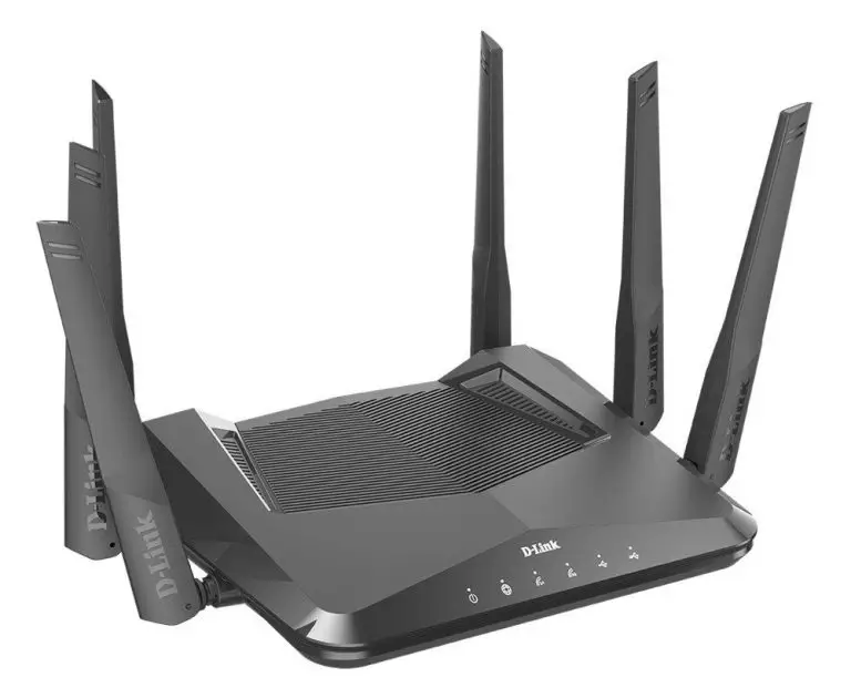
Specifications
| Technical Specifications | ||
| General | ||
| Device Interfaces | • One 10/100/1000 Mbps Gigabit Ethernet WAN port
• Four 10/100/1000 Mbps Gigabit Ethernet LAN ports • IEEE 802.11 ax1/ac/n/g/b/a wireless LAN |
• One SuperSpeed USB 3.0 port
• One USB 2.0 port |
| LEDs | • Power
• Internet • USB 2.0 |
• Wi-Fi 2.4GHz
• Wi-Fi 5GHz • USB 3.0 |
| Antenna Type | • Six external antennas | |
| Wi-Fi Data Rate | • 2.4 GHz
• Up to 600 Mbps2 |
• 5 GHz
• Up to 4200 Mbps2 |
| Standards | • IEEE 802.11ax
• IEEE 802.11ac • IEEE 802.11n • IEEE 802.11g • IEEE 802.11b |
• IEEE 802.11a
• IEEE 802.3u • IEEE 802.3ab • IEEE 802.3az |
| Minimum Requirements | • Windows 10/8.1/8/7/Vista or MAC OS X 10.6 or higher
• Supports Internet Explorer 10, Firefox 28.0, Chrome 28.0, Safari 6.0, and up |
• Network Interface Card
• Cable/DSL modem or other Internet service provider equipment with Ethernet port |
| Functionality | ||
| Security | • 802.11 128-bit AES
• Latest Wi-Fi security with 128-bit encryption |
• WPS (Wi-Fi Protected Setup) |
| Advanced Features | • D-Link Wi-Fi App Setup and Configuration
• QoS (Quality of Service) • DMZ (De-militarized Zone) |
• Firewall – Network Address Translation (NAT)
• Guest Zone • Multicast Support |
| Physical | ||
| Dimensions | • 241.35 x 338.80 x 211.32 mm (9.5 x 13.3 x 8.32 in) | |
| Weight | • 732 g (1.6 lbs) | |
| Power Adaptor | • Input: 100 to 240 V AC, 50 / 60 Hz | • Output: 12 V DC, 2A |
| Temperature | • Operating: 0 to 40 °C (32 to 104 °F) | • Storage: -20 to 65 °C (-4 to 149 °F) |
| Humidity | • Operating: 10% to 90% non-condensing | • Storage: 5% to 95% non-condensing |
| Certifications | • FCC
• IC • NCC |
• CE
• RCM |
| Order Information | ||
| Part Number | Description | |
| DIR-X4860 | AX4800 Wi-Fi Router | |
- The DIR-X4860 may not support all of the mandatory features, established in Draft 3.0 of the IEEE 802.11ax specifications
- Maximum wireless signal rate derived from IEEE Standard 802.11ac and 802.11n specifications. Actual data throughput will vary. Network conditions and environmental factors, including volume of network traffic, building materials and construction, and network overhead, may lower actual data throughput rate. Environmental factors will adversely affect wireless signal range.

QUICK INSTALLATION GUIDE
DWA-123 WIRELESS N 150 USB ADAPTER
CD SET-UP WIZARD
SET-UP WIZARD CD
The CD contains all of the instructions required to set up DWA-123

INSERT CD
Insert the CD into the CD drive of your computer.
The set-up wizard should start automatically. Make sure that your internet connection is active. (Do not plug in DWA-123 yet)

SET-UP WIZARD
Select your language from the list of options and follow the steps within the wizard to complete the set-up of the DWA-123
SET-UP AND CONFIGURATION PROBLEMS
- IF I’VE LOST MY CD WHAT CAN I DO?
The CD contains software drivers and manuals which can be obtained from D-Link (see Technical Support below). Windows XP, Vista, Windows 7, 8 in most cases will automatically install the correct drivers. - IF I’VE FORGOTTEN MY WIRELESS ENCRYPTION KEY?
The wireless encryption key is configured at the Wireless Access Point, Router, or DSL Modem Router. If you are unable to obtain your encryption key, the only solution would be to re-configure your Access Point/Router to use a new encryption key. Please contact your Wireless Access Point/Router/DSL Modem Router manufacturer. - WHY CAN’T I GET A WIRELESS CONNECTION?
– Check that your DWA-123 is plugged in properly to the USB port or try to plug the DWA-123 into another USB port if available.
– The LED on the DWA-123 should be lit, otherwise, there could be a physical fault on the USB port or the driver is not installed properly.
– Ensure that the wireless settings on the DWA-123 match the settings on your Access Point/Router. Please check and confirm your settings.
Wireless Network Name (SSID)
Wireless Encryption Key
Wireless Security Method (E.g. WEP, WPA2)
To check whether a Wireless connection has been made, in the Windows System Tray (bottom right). Red means no valid connections have been made.
– Check that your Internet is working fine on existing computers.
– Ensure that you have followed and completed the software installation process, otherwise, please re-install the software. The LED on the DWA-123 should come on after software installation.
TECHNICAL SUPPORT
You can find software updates and user documentation on the D-Link website.
Tech Support for customers in
Australia:
Tel: 1300-700-100
24/7 Technical Support
Web: http://www.dlink.com.au
E-mail: [email protected]
India:
Tel: +91-832-2856000 or 1860-233-3999
Web: www.dlink.co.in
E-Mail: [email protected]
Singapore, Thailand, Indonesia, Malaysia, Philippines, Vietnam:
Singapore – www.dlink.com.sg
Thailand – www.dlink.co.th
Indonesia – www.dlink.co.id
Malaysia – www.dlink.com.my
Philippines – www.dlink.com.ph
Vietnam – www.dlink.com.vn
Korea:
Tel : +82-2-2028-1810
Monday to Friday 9:00am to 6:00pm
Web : http://d-link.co.kr
E-mail : [email protected]
New Zealand:
Tel: 0800-900-900
24/7 Technical Support
Web: http://www.dlink.co.nz
E-mail: [email protected]
South Africa and Sub Sahara Region:
Tel: +27 12 661 2025
08600 DLINK (for South Africa only)
Monday to Friday 8:30am to 9:00pm
South Africa Time
Web: http://www.d-link.co.za
E-mail: [email protected]
D-Link Middle East – Dubai, U.A.E.
Plot No. S31102,
Jebel Ali Free Zone South, P.O.Box 18224, Dubai, U.A.E.
Tel: +971-4-8809022
Fax: +971-4-8809066 / 8809069
Technical Support: +971-4-8809033
General Inquiries: [email protected]
Tech Support: [email protected]
Egypt
1, Makram Ebeid Street –
City Light Building – floor 5
Nasrcity – Cairo, Egypt
Tel.: +2 02 23521593 – +2 02 23520852
Technical Support: +2 02 26738470
General Inquiries: [email protected]
Tech Support: [email protected]
Kingdom of Saudi Arabia
Office # 84 ,
Al Khaleej Building ( Mujamathu Al-Khaleej)
Opp. King Fahd Road, Olaya
Riyadh – Saudi Arabia
Tel: +966 1121 70008
Technical Support: +966 1121 70009
General Inquiries: [email protected]
Tech Support: [email protected]
Pakistan
Islamabad Office:
61-A, Jinnah Avenue, Blue Area,
Suite # 11, EBC, Saudi Pak Tower,
Islamabad – Pakistan
Tel.: +92-51-2800397, 2800398
Fax: +92-51-2800399
Karachi Office:
D-147/1, KDA Scheme # 1,
Opposite Mudassir Park, Karsaz Road,
Karachi – Pakistan
Phone: +92-21-34548158, 34326649
Fax: +92-21-4375727
Technical Support: +92-2134548310, 34305069
General Inquiries: [email protected]
Tech Support: [email protected]
Morocco
M.I.T.C
Route de Nouaceur angle RS et
CT 1029 Bureau N° 312 ET 337
Casablanca , Maroc
Phone : +212 663 72 73 24
Email: [email protected]
Lebanon RMA center
Dbayeh/Lebanon
PO Box:901589
Tel: +961 4 54 49 71 Ext:14
Fax: +961 4 54 49 71 Ext:12
Email: [email protected]
Bahrain
Technical Support: +973 1 3332904
Kuwait: Technical Support: + 965 22453939 / +965 22453949
DSL-G225
Introduction
This guide is for DSL-G225 with firmware ver. 1.04.
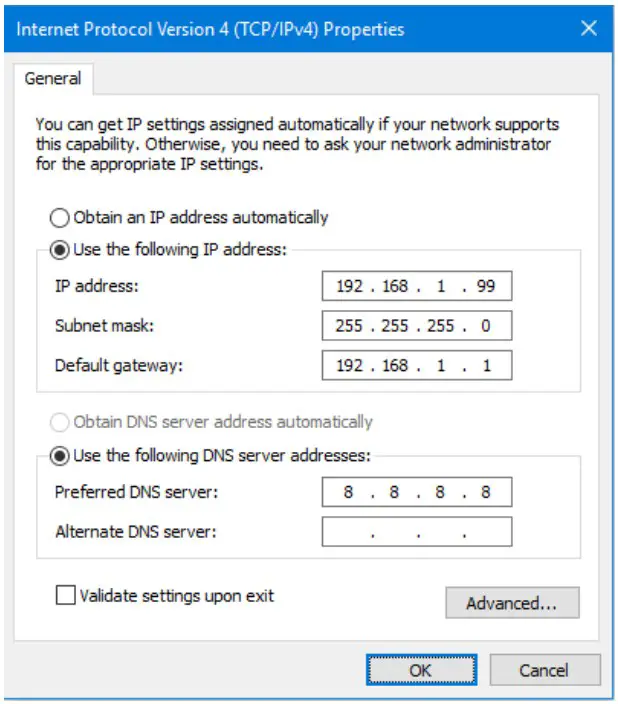
Before proceeding with this setup please set your computer temporarily with a static IP address from 192.168.1.x range (e.g. 192.168.1.99):
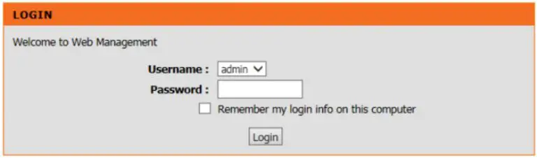
Open your Internet browser e.g. Internet Explorer, Firefox, Chrome, Safari, etc. and enter the IP address of your DLink modem in the address bar: http://192.168.1.1.

When prompted, type in the Password. If you have not changed the password for the modem administration, the factory password is “admin”.
There are two ways to setup your modem in Bridge Mode: using the Setup Wizard and using Manual Configuration.
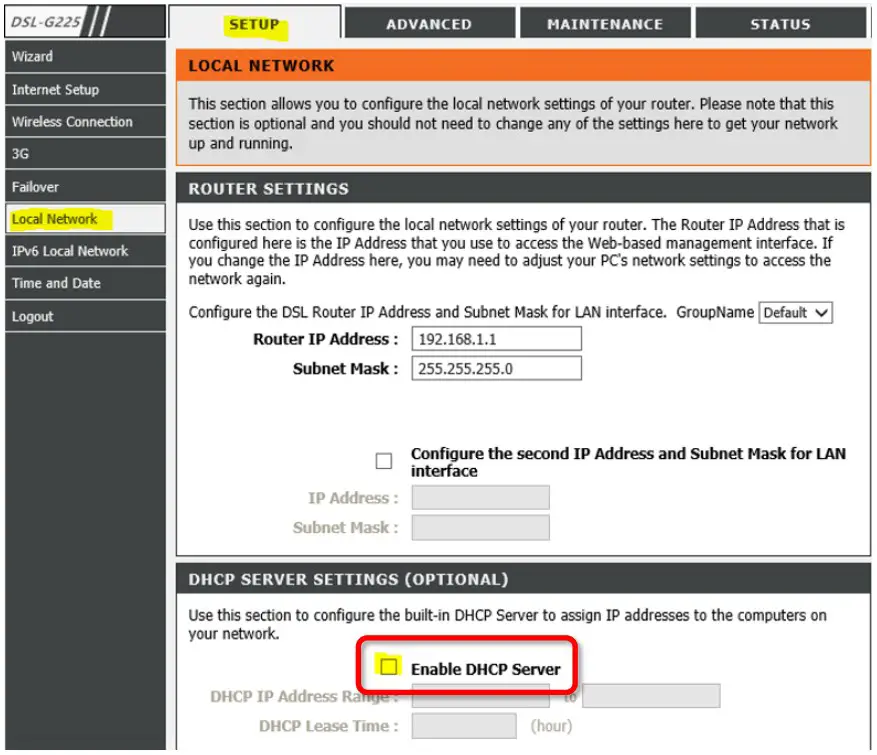
Setup using the Setup Wizard
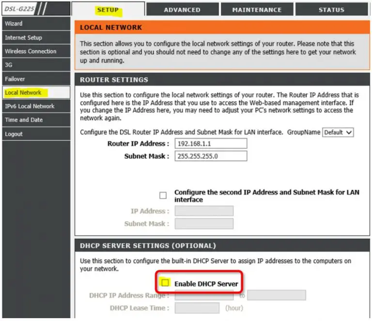
Step 1. After logging into the modem’s configuration pages, go to SETUP > Local Network. Un-check the “Enable DHCP Server” option.
Click on Save/Apply.
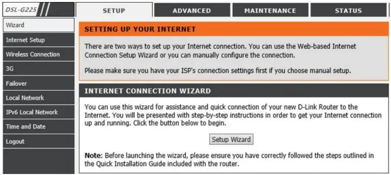
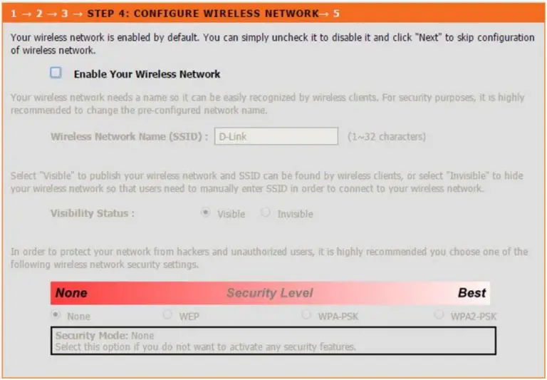
Step 2. Go to SETUP > Wizard > click on the “Setup Wizard” button.
Follow the steps in the Setup Wizard.
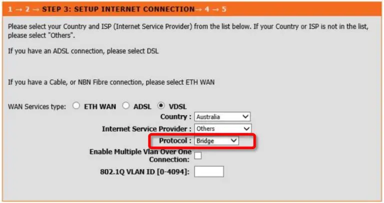
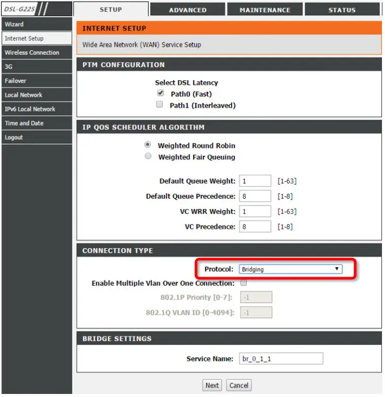
Choose ADSL or VDSL, depending on the type of technology used for your Internet connection.
Set Protocol to “Bridge”.
It is recommended to disable the modem’s Wi-Fi:
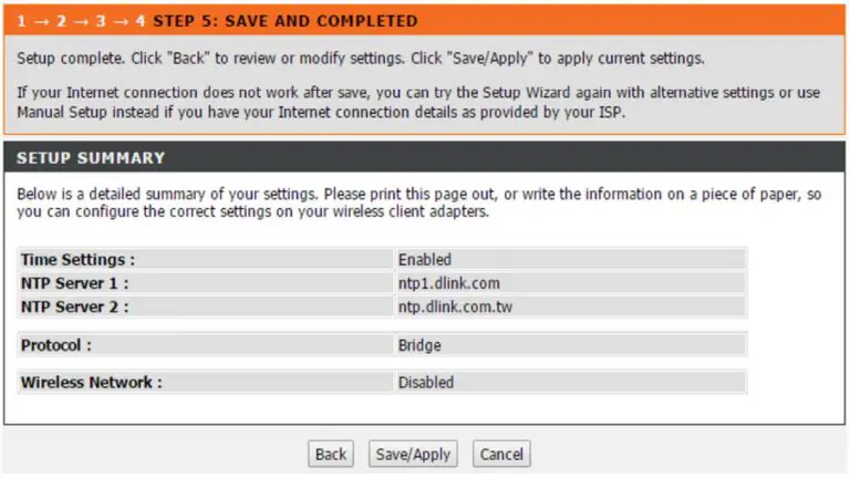
Click on “Save/Apply” to finish the Setup Wizard. The setup is complete.
Manual Setup
Step 1. After logging into the modem’s configuration pages, go to SETUP > Local Network.
Un-check the “Enable DHCP Server” option.
Click on Save/Apply.
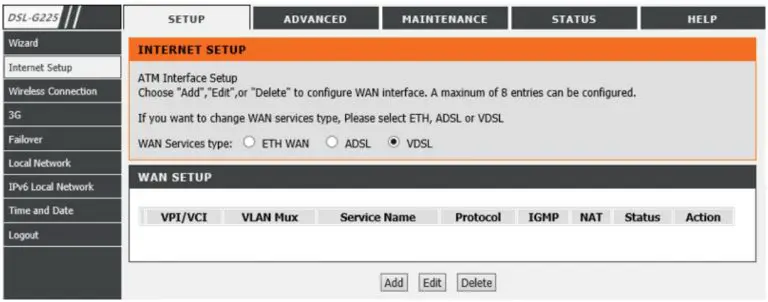
Step 2. Go to SETUP > Internet Setup.
If there are any existing profiles listed in the WAN Setup table, delete them.
Choose ADSL or VDSL, depending on the type of technology used for your Internet connection.
Click on “Add”.
Set Protocol to “Bridging” and click on Next.
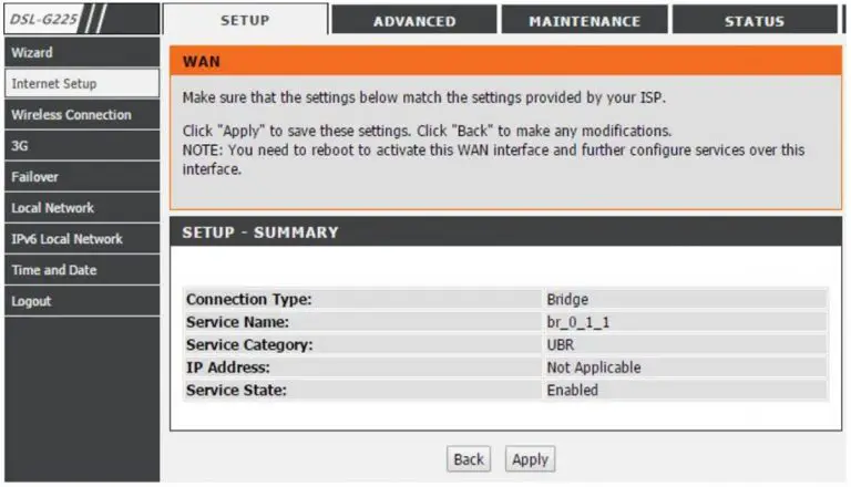
Click on “Apply” to finish the setup. The modem setup is complete.
Please note that in Bridge Mode the DSL-G225 modem acts as a transparent device. If your Internet provider requires PPPoE authentication or VLAN tagging, you need to enable these options on the device connected to the LAN port of the DSL-G225 modem.
Specifications
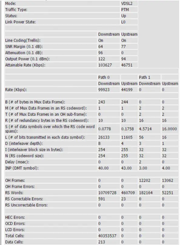
After successful VDSL sync
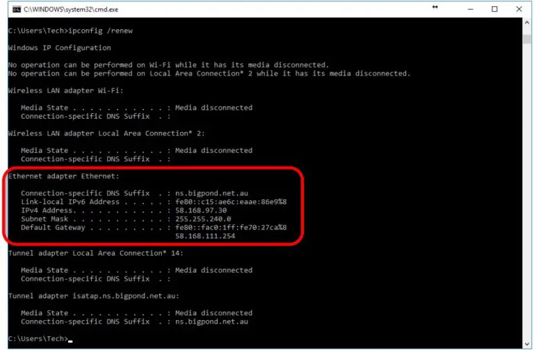
The computer behind the DSL-G225 in Bridge Mode obtains public IP address from the ISP:
Support
D-Link Technical Support – How to setup DSL-G225 in Bridge Mode Page
]]>AC1750 Wi-Fi
Range Extender
DAP-1720
Quick Install Guide
Package Contents
 DAP-1720 AC1750 Wi-Fi Range Extender
 Wi-Fi Configuration Card
 Quick Install Guide
If any of the above items are missing, please contact your reseller.
Before You Begin
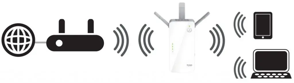
- Make sure the area that you want to plug the extender into has a solid connection to your router. Use a wireless laptop, tablet, or mobile phone in that area to test the connection to verify.
- If your wireless router or access point does not support WPS, follow the steps under Configure the DAP-1720 Using a Web Browser to connect to the DAP-1720 and run the Setup Wizard. If you are not sure how to enable WPS on your wireless router, please refer to your router’s user manual.
Product Overview
| LED | Color | Status | Description |
| Status LED | Red | Solid | The device is powering on/booting up. |
| Amber | Blinking | The device is ready but not connected to an uplink router. | |
| Green | Solid | This indicates that the DAP-1720 is securely connected to your wireless router or access point. | |
| Blinking | The WPS button has been pushed and the device is processing a connection. |
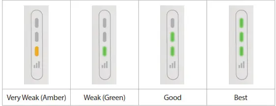
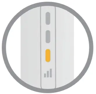
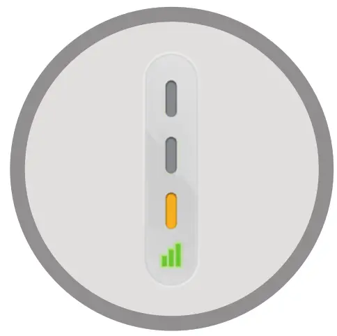
Signal Strength Indicators

Connect to Your Router Using WPS
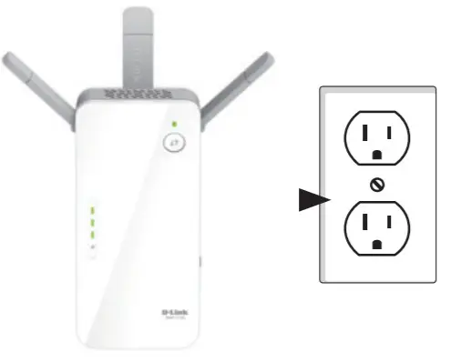
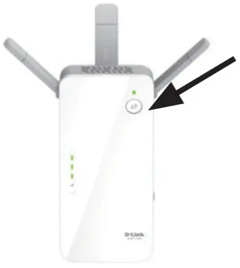
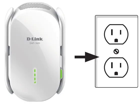
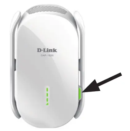
1.Find an available outlet near your wireless router. Plugin the DAP-1720 and wait until the Status LED is blinking amber.
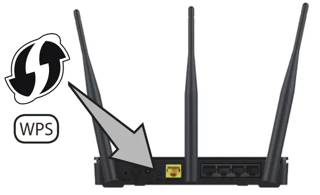
2.Press the WPS (Wi-Fi Protected Setup) button on your wireless router.
3.Within one minute, press the WPS button on the DAP-1720. The Status LED will start to blink green.
4.When the Status LED turns solid green, this indicates that the DAP-1720 is securely connected to your wireless router or access point. You can now unplug and move the DAP-1720 to a location between your wireless router and the area that you need wireless coverage.
If the signal strength indicators are showing one single amber bar or if the DAP-1720 is not connecting, move the DAP-1720 to a wall outlet closer to your wireless router or access point.
Connect Your Wireless Devices
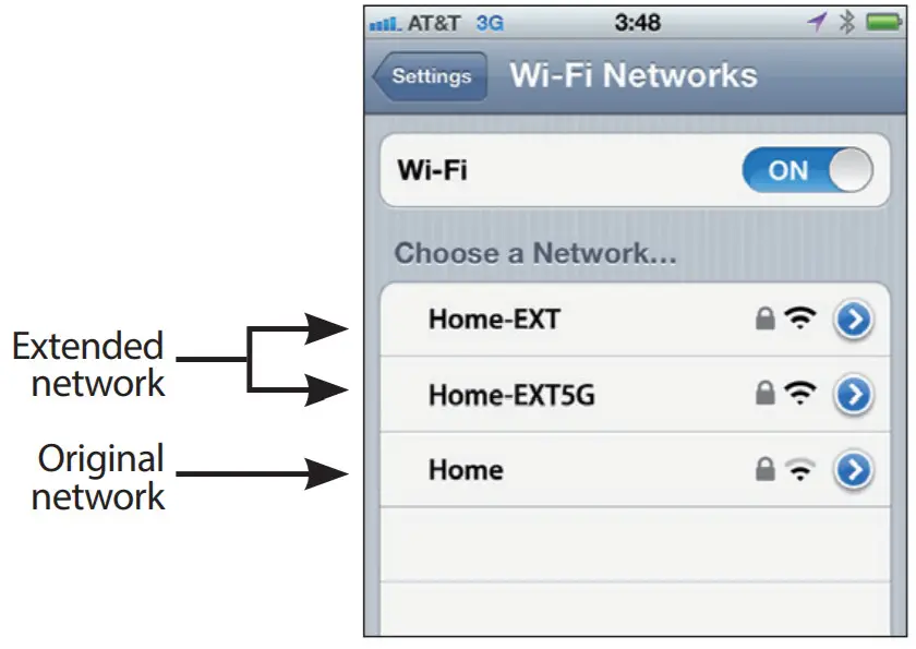
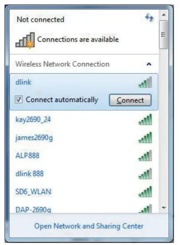
5.From your wireless device go to the Wireless Utility to display the available wireless networks.
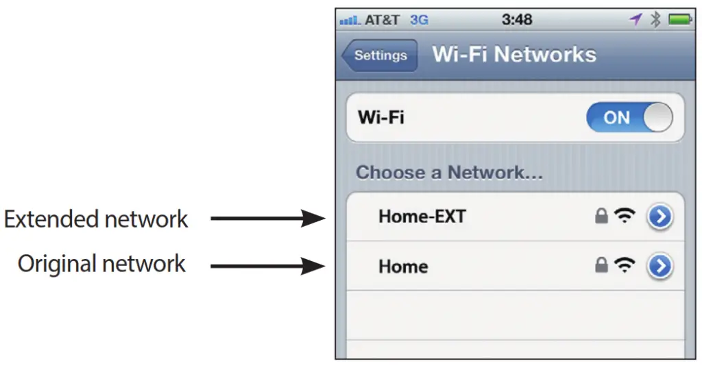
The SSID on the DAP-1720 will automatically be assigned the following:
- 2.4GHz (Your Router’s SSID)-EXT
- 5GHz (Your Router’s SSID)-EXT5G
The Wi-Fi password for the DAP-1720 will be the same as your router.
Repeat step 5 to connect additional Wi-Fi devices to the DAP-1720.
6.Your device is now connected to the DAP-1720 and can connect to your wireless router. If you want to change your network settings, password, etc., follow the steps on the next page to configure the DAP-1720. To connect additional devices, repeat step 5.
Your setup is complete!
Configure the DAP-1720 Using a Web Browser (Optional)
You may log into the web-based configuration utility on the DAP-1720 to perform the following tasks:
- Upgrade firmware
- Change wireless and network settings
- Change the login password
1.Plug the DAP-1720 into an available outlet near your router. You may move it to a more suitable location after configuration.
2.Open the wireless utility on your wireless device or computer. Select the Wi-Fi Network name (from the Wi-Fi Configuration Card) and enter the password. You may also connect the DAP-1720 to your router or computer using an Ethernet cable.
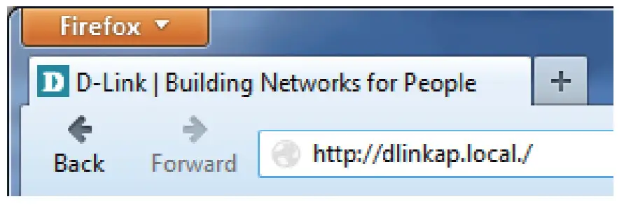
3.Open a web browser (e.g., Internet Explorer, Firefox, Safari, or Chrome) and enter http://dlinkap.local./. You may also enter the IP address of the DAP-1720.
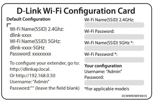
Note: The default IP address is 192.168.0.50. Once the DAP-1720 connects to your router, it will get assigned a new IP address based on your router/network’s DHCP settings. You will need to log in to your router and view the DHCP table to see what IP address was assigned to the DAP-1720. The MAC address is printed on the label on the device.
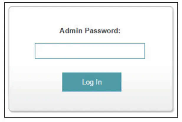
4.Once you connect, the login page will appear. Enter your password and click Log in. By default the password is blank.
Note: The default IP address is 192.168.0.50. Once the DAP-1720 connects to your router, it will get assigned a new IP address based on your router/network’s DHCP settings. You will need to log in to your router and view the DHCP table to see what IP address was assigned to the DAP-1720. The MAC address is printed on the label on the device.
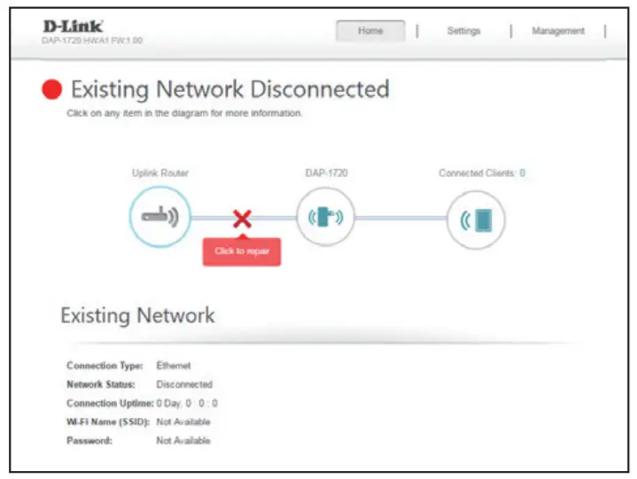
5.The home page will display your current status. A green checkmark represents a successful connection to your wireless router or Access Point (AP). A red X means there is not a connection to your router or access point. Click the Uplink Router icon.
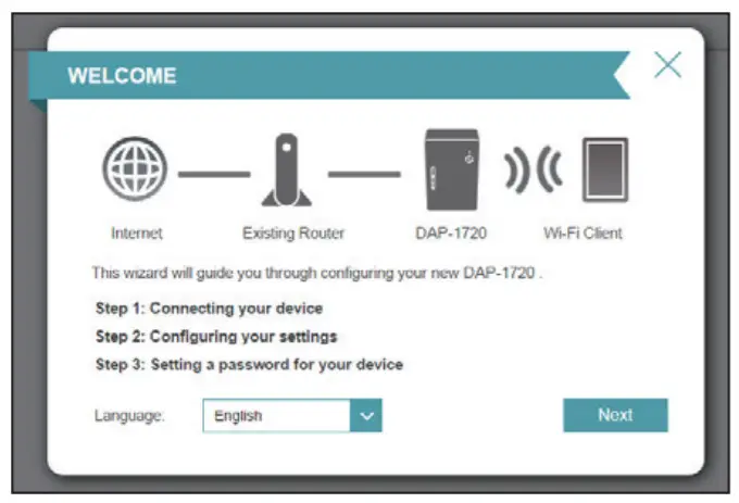
6.Select your language from the drop-down menu and then click Next.
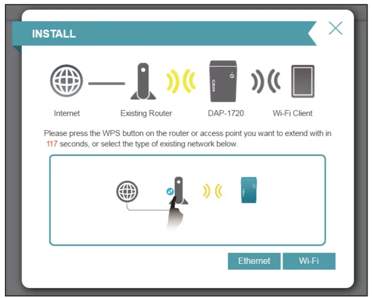
 7.The WPS process will be started on the DAP-1720 automatically. Press the WPS button on your wireless router or access point.
If you want to manually select the wireless network you want to extend, click Extend an existing wireless network and go to the next page. If you want to connect the DAP-1720 to a wired network using an Ethernet cable, click Add wireless to your wired network and skip to page 11.
 If you clicked “Extend an existing wireless network”
8.A list of detected wireless networks within range of the DAP-1720 will appear. Click on the network you want to extend. If you want to manually type in the Wi-Fi network name (SSID), click Manual at the bottom.
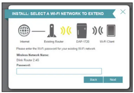
9.If your wireless network is secure/encrypted, enter the Wi-Fi password and click Next to continue.
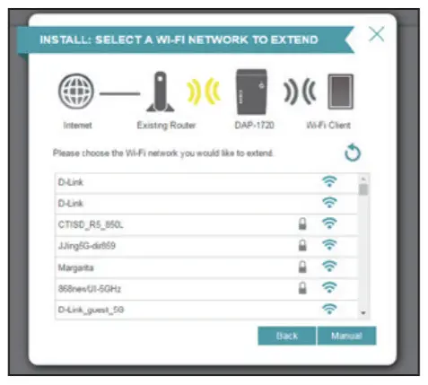
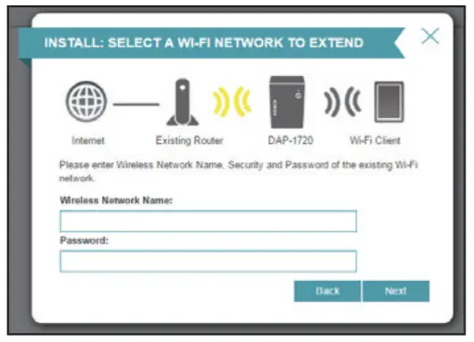
If you clicked Manual, enter the SSID and security information (Wi-Fi password) of the wireless network you want to extend and click Next to continue.
If you clicked “Add wireless to your wired network”
8.Connect the DAP-1720 to your network using an Ethernet cable. The wizard will automatically go to step 10 on the next page. If you wish to connect the DAP-1720 later, click Skip.
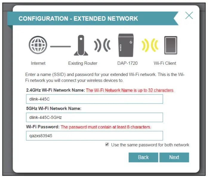
10.Enter a new Wi-Fi network name for the DAP-1720 and enter a new Wi-Fi password. Click Next to continue.
11.Enter an administrator password for the DAP-1720. This is the password you will use to enter the web-based configuration. Click Next to continue.
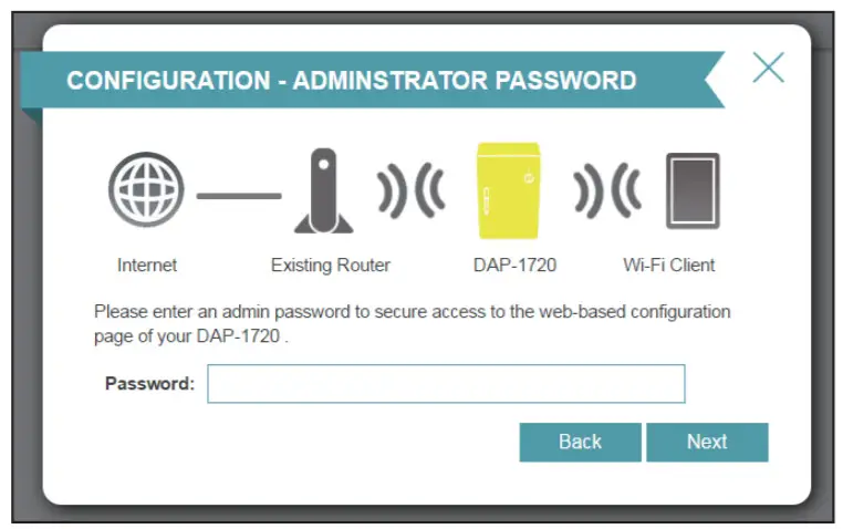
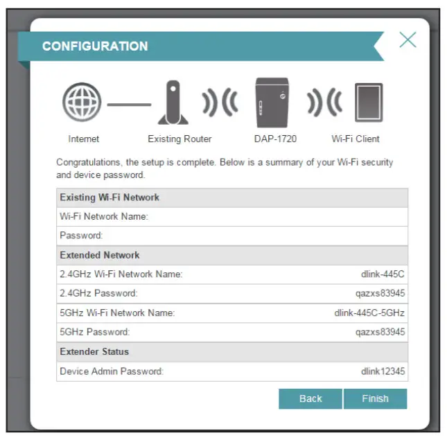
12.A summary page will display your settings. Click Finish and the DAP-1720 will reboot. If you want to make any changes, click Back.
The setup is now complete. Allow about two minutes for the DAP-1720 reboot. Verify that the Status light is green and the signal strength indicators are lit. You can now unplug the DAP-1720 and connect to a different location if needed.
Troubleshooting
Why can’t I connect to my wireless router or does my wireless connection drops?
- Verify that the DAP-1720 is within range of your wireless router. Try plugging it into a location closer to the router and verify the Status LED is solid green.
- Note that when repeating a wireless signal from a router or access point, devices connected to the repeater will not get the same speed/throughput as when connected directly to the router.
How do I change the wireless settings on the DAP-1720?
- Open a web browser (e.g., Internet Explorer, Firefox, Chrome, or Safari) and go to http://dlinkap.local./ or enter the IP address (http://192.168.0.50 by default).
- At the login screen, enter your password and click Log in.
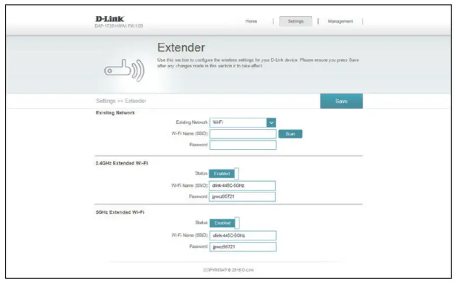
- Go to Setup > Wireless.
- Enter a new Wi-Fi Network Name (SSID) for the 2.4GHz and 5GHz bands, and modify the security (Wi-Fi password) settings as needed.
- Click Save.
Note: If you have changed the Wi-Fi Network name, the device you are currently using to connect to the DAP-1720 will drop. You will need to open your wireless utility and connect to the DAP-1720 using the new network name and password.
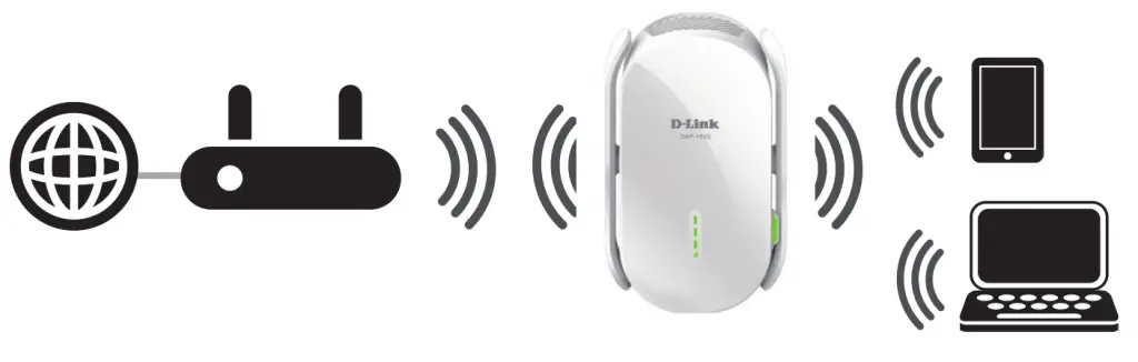
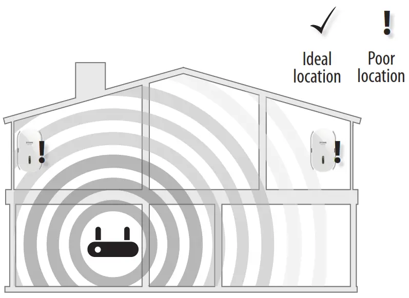
Where should I place my DAP-1720 when using it as a range extender?
A Range Extender only works as well as the signal it is extending.
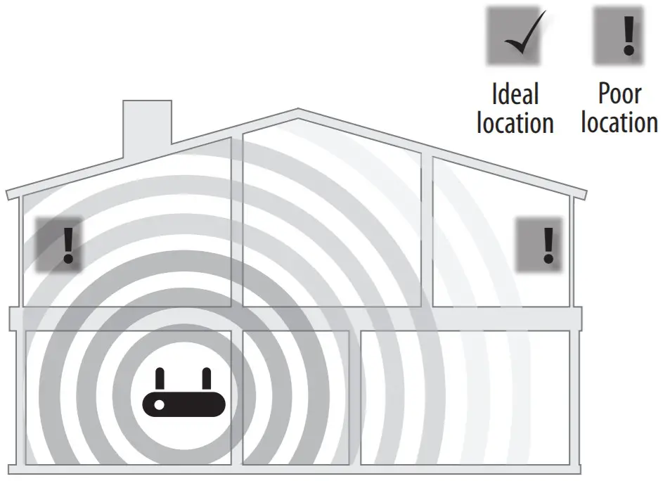
Therefore, proper placement of your DAP-1720 is important in achieving desired results.
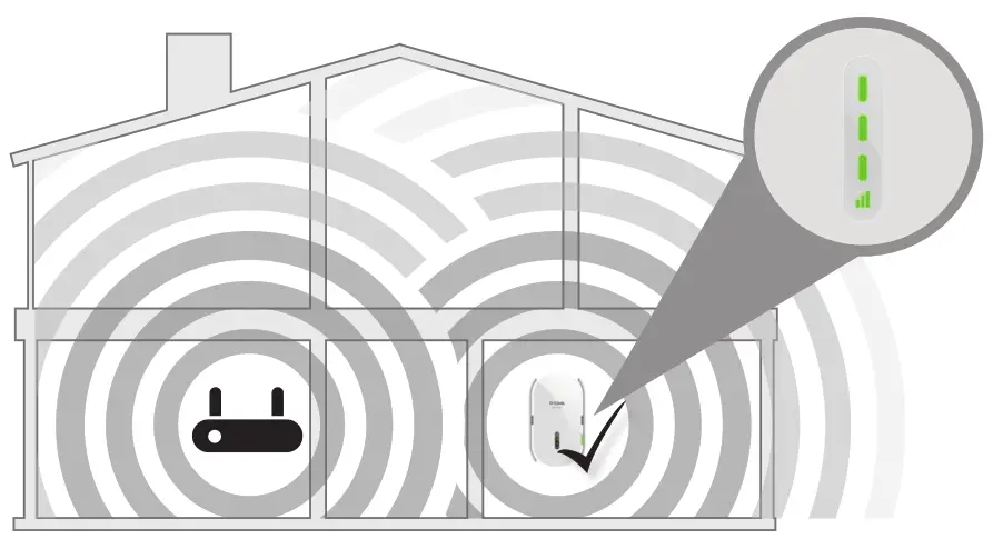
For best performance, place your DAP-1720 in between your router and your dead zone, making sure it’s placed in a location where the Wi-Fi signal is still strong. Use the Smart Signal Indicator to help find a location with a strong signal. The more bars lit on the signal indicator, the stronger the Wi-Fi signal is.
What if I forgot my DAP-1720 password?
- If you forgot your password or want to reset the DAP1720
back to the factory default settings, press and hold the reset button on the bottom of the extender using a paper clip and release after a minimum of 10 seconds. The Status light will turn red.
Note: This process will erase all your settings. - You may repeat the WPS process on page 5. Follow the steps under Connect to Your Router Using WPS.
GPL Code Statement
This D-Link product includes software code developed by third parties, including software code subject to the GNU General Public License (“GPL”) or GNU Lesser
General Public License (“LGPL”). As applicable, the terms of the GPL and LGPL, and information on obtaining access to the GPL code and LGPL Code used in this
product, are available to you at:
http://tsd.dlink.com.tw/GPL.asp
The GPL Code and LGPL Code used in this product are distributed WITHOUT ANY WARRANTY and are subject to the copyrights of one or more authors. For details, see the GPL code and the LGPL code for this product and the terms of the GPL and LGPL.
Written Offer for GPL and LGPL Source Code
Where such specific license terms entitle you to the source code of such software, D-Link will provide upon written request via email and/or traditional paper mail the applicable GPL and LGPL source code files via CD-ROM for a nominal cost to cover shipping and media charges as allowed under the GPL and LGPL.
Please direct all inquiries to:
Email: [email protected]
Snail Mail:
Attn: GPLSOURCE REQUEST
D-Link Systems, Inc.
17595 Mt. Herrmann Street
Fountain Valley, CA 92708
GNU GENERAL PUBLIC LICENSE
Version 3, 29 June 2007
Copyright (C) 2007 Free Software Foundation, Inc. <http://fsf.org/>
View the full GPL Code Statement at http://www.gnu.org/licenses/gpl.html
Notes
Technical Support
This guide is for the first-time configuration. Please refer to the user manual to learn more.
U.S. and Canadian customers can contact D-Link Technical Support through our website.
USA
 http://support.dlink.com/DAP-1720
Canada
http://support.dlink.ca/DAP-1720
![]()
Version 1.02(NA)_85X125
December 12, 2016
6AP1720Q.D03G
©2017 D-Link. All rights reserved. D-Link and the D-Link logo are trademarks or registered trademarks of D-Link Corporation or its subsidiaries. All other third-party marks mentioned herein may be trademarks of their respective owners. This publication may not be reproduced, in whole or in part, without prior express written permission from D-Link Systems, Inc.
]]>AC2000 Wi-Fi Range Extender
Quick Install Guide
DAP-1820
Package Contents
 DAP-1820 AC2000 Wi-Fi Range Extender
 Quick Install Card
 Quick Install Guide
If any of the above items are missing, please contact your reseller.
Before You Begin
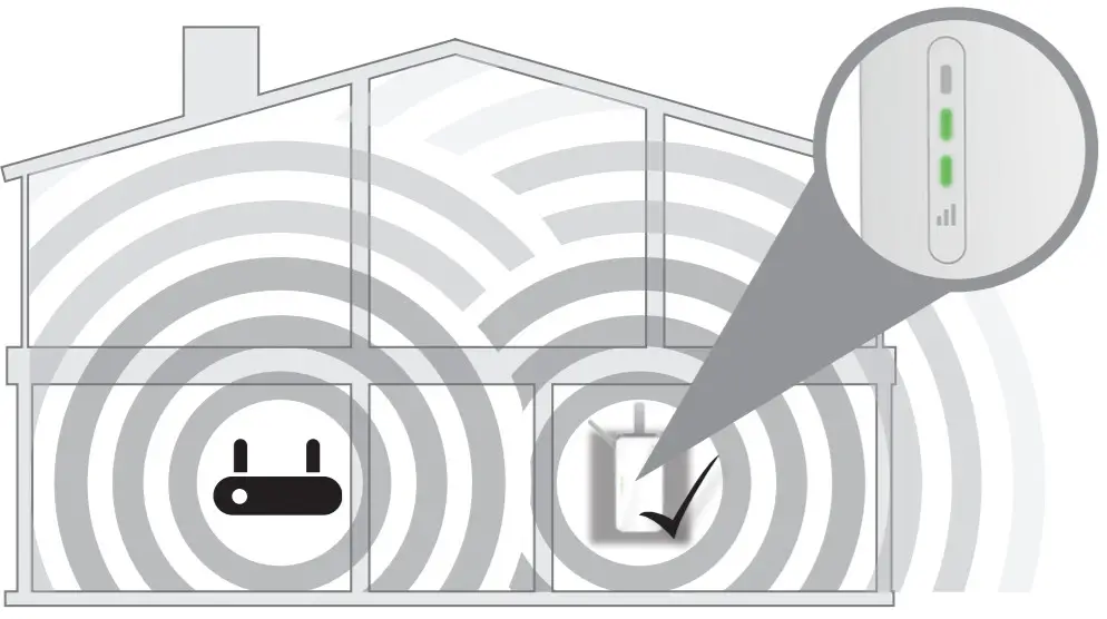
- For setup, you will want your Range Extender to be plugged into an available outlet as close to your Wi-Fi Router as possible. Once setup is complete, you can plug it into an outlet in an area between your Wi-Fi router and where you want improved coverage. See the Troubleshooting section for tips on Wi-Fi Extender placement.
- If your wireless router or access point does not have a WPS button (
 ), follow the steps under Method Two: D-Link Wi-Fi Setup to set up your Range Extender.
Product Overview

| LED | Color | Status | Description |
| Status LED | Red | Solid | The device is powering on. |
| Amber | Blinking | The device is ready but not connected to a router or access point. | |
| Green | Solid | Indicates that the range extender is connected to your wireless router or access point. | |
| Blinking | The WPS button has been pushed and the device is establishing a connection. |
Signal Strength Indicator

There are two easy ways to set up your Range Extender.
It is recommended that you use Method One. If your router does not have a WPS button (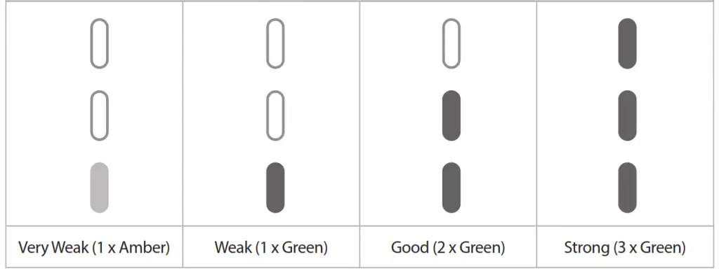 )WPS, see Method Two: D-Link Wi-Fi Setup, on page 6.
Method One: Quick WPS Setup
- Plug your Range Extender into an available outlet near your wireless router and wait until the Status LED is blinking amber (this may take up to 3 minutes). You can move it to a more suitable location after it is set up.

- Press the WPS (Wi-Fi Protected Setup) button on your wireless router for 3 seconds. Look for the WPS light ( )WPS on your router and make sure it is blinking. If it does not blink, see the important note below.

IMPORTANT
WPS may be disabled on some Routers or ModemsIf the WPS Status LED on your Router or Modem does not start blinking when you have pressed the WPS button, try again and hold it a little longer. If it still does not blink, STOP, and configure your Range Extender using Method Two: D-Link Wi-FSetup, on page 6.
3. Once confirmed that the WPS light is blinking on your router, within one minute, press the WPS button on your Range Extender for 2-3 seconds. The Status LED should start to blink green.
4 . When the Status LED turns solid green (may take up to 3 minutes), this indicates that your Range Extender is connected to your wireless router. You can now unplug and move your Range Extender to a location between your wireless router and the area where you want wireless coverage.
Note: If the Status LED on your Range Extender does not turn solid green after running WPS setup, try resetting the unit (see Troubleshooting – What if I forgot my Range extenders Admin password or want to reset my Range Extender?) and try WPS setup again. If it still does not turn solid green after following all the steps, see Method Two: D-Link Wi-Fi Setup, on page 6.
If after moving your Range Extender, the signal the strength indicator is showing one single amber bar or if your Range Extender LED does not turn solid green within 3 minutes, ove your Range Extender to a wall outlet closer to your wireless router.
Signal Strength Indicator
Your setup is complete! To connect your wireless devices to your Range Extender, see Connect Your Wireless Devices, on page 7.
Method Two: D-Link Wi-Fi Setup
1.Search for “D-Link Wi-Fi” on the App Store or Google Play and download the D-Link Wi-Fi App to your iPhone, iPad, or Android device.

iOS

Android
D-Link Wi-Fi App
2. Once your app is installed, tap on the D-Link Wi-Fi icon from your mobile device. Please follow the on-screen instructions to complete the setup.
When asked to scan the setup QR Code, scan the QR Code located on the Quick Install Card.
Your setup is complete! To connect your wireless devices to your Range Extender, see Connect Your Wireless Devices, on page 7
Connect Your Wireless Devices
1. From your wireless device go to Wi-Fi Settings to display the available wireless networks.
If Quick WPS Setup was used to set up your Range Extender, the SSID on your Range Extender will automatically be assigned the following:
• (Your Router’s SSID)-EXT
The Wi-Fi Password for your Range Extender will be the same as your router’s Wi-Fi password.
If D-Link Wi-Fi Setup was used to set up your Range Extender, use the SSID and Wi-Fi Password you specified during the setup process.
SmartConnect: By default, SmartConnect is enabled on this Range Extender. SmartConnect will automatically steer your device to the optimal wireless band(2.4GHz or 5GHz) according to current network traffic. When enabled, you will only see one wireless network name (SSID) from your Range Extender.
2. Your device is now connected to your Range Extender. To connect additional devices, repeat step 1.
Troubleshooting
Why can’t I connect to my wireless router or does my wireless connection drops?
1. Verify that your Range Extender is within the range of your wireless router. Try plugging it into a location closer to the router and verify the Status LED is solid green.
2. Note that when extending a wireless signal from a router or access point, devices connected to the Range Extender will not get the same speed/throughput as when connected directly to the router.
How do I change the wireless settings on my Range Extender?
1. Open a web browser (e.g., Internet Explorer, Firefox, Chrome, or Safari) and go to http://dlinkap.local./
2. At the login screen, enter your Admin Password (If WPS Setup was used, the password is blank by default – just leave blank) and click Log in.
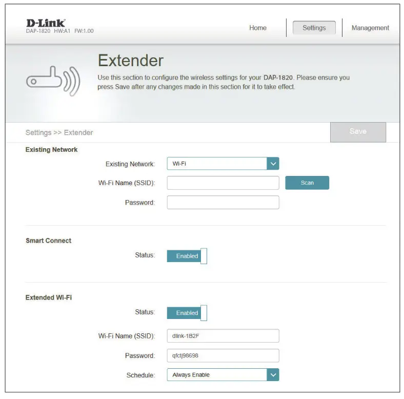
3. Go to Settings > Extender.
4. Enter a new Wi-Fi Network Name (SSID) and modify the security (Wi-Fi password)
settings as needed.
5. Click Save.
Note: If you have changed the Wi-Fi Network name, the device you are currently using to connect to your Range Extender will drop. You will need to go to your Wi-Fi settings and connect to your Range Extender using the new network name and password.
Where should I place my Range Extender for best performance?
A Range Extender only works as well as the signal it is extending. Therefore, proper placement of your Range Extender is important in achieving desired results.
For best performance, place your Range Extender in between your router and your dead zone, making sure it is placed in a location where the Wi-Fi signal is still strong. Use the Smart Signal Indicator to help find a location with a strong signal. The more bars lit on the signal indicator, the stronger the Wi-Fi signal is.
What if I forgot my Range Extender’s Admin password or want to reset my Range Extender?
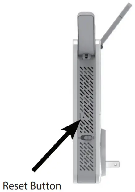
- If you forgot your Admin password or want to reset your Range Extender back to the factory default settings, press and hold the reset button on the bottom of the extender using a paper clip and release after a minimum of 10 seconds. The Status light will turn red.

Note: This process will erase all your settings. - Setup your Range Extender using your preferred method.
What if the WPS setup is not working?
WPS may be disabled on some Routers or Modems. If the WPS Status LED on your Router or Modem does not start blinking when you have pressed the WPS button, try to gain and hold it a little longer. If it still does not blink, STOP, and configure your Range Extender using Method Two: D-Link WiFi Setup, on page 6.
GPL Code Statement
This D-Link product includes software code developed by third parties, including software code subject to the GNU General Public License (“GPL”) or GNU Lesser General Public License (“LGPL”). As applicable, the terms of the GPL and LGPL, and information on obtaining access to the GPL code and LGPL Code used in this
product, are available to view the full GPL Code Statement at:
https://tsd.dlink.com.tw/GPL
The GPL Code and LGPL Code used in this product are distributed WITHOUT ANY WARRANTY and are subject to the copyrights of one or more authors. For details, see the PL code and the LGPL code for this product and the terms of the GPL and LGPL.
Written Offer for GPL and LGPL Source Code
Where such specific license terms entitle you to the source code of such software, D-Link will provide upon written request via email and/or traditional paper mail the pplicable GPL and LGPLsource code files via CD-ROM for a nominal cost to cover shipping and media charges as allowed under the GPL and LGPL.
Please direct all inquiries to:
Email:
[email protected]
Snail Mail:
Attn: GPLSOURCE REQUEST
D-Link Systems, Inc.
17595 Mt. Herrmann Street
Fountain Valley, CA 92708
Technical Support
This guide is for the first-time configuration. Please refer to the user manual to learn more. U.S. customers can contact D-Link Technical Support through our website.
USA
![]() http://support.dlink.com/
http://support.dlink.com/
![]() 877-453-5465
877-453-5465
![]()
Version 1.10(US)_90x130
July 02, 2019
610000009625
©2019 D-Link. All rights reserved. D-Link and the D-Link logo are trademarks or registered trademarks of
D-Link Corporation or its subsidiaries. All other third-party marks mentioned herein may be trademarks
of their respective owners. This publication may not be reproduced, in whole or in part, without prior
express written permission from D-Link Systems, Inc.
DSP-W320
Outdoor Wi-Fi Smart Plug
User Manual
Manual Overview
D-Link reserves the right to revise this publication and to make changes in the content hereof without obligation to notify any person or organization of such revisions or changes. Information in this document may become obsolete as our services and websites develop and change. Please refer to the www.mydlink.com website for the most current information.
Manual Revisions
| Revision | Date | Description |
| 1.00 | August 15, 2019 | Initial release |
Trademarks
D-Link and the D-Link logo are trademarks or registered trademarks of D-Link Corporation or its subsidiaries in the United States or other countries. All other company or product names mentioned herein are trademarks or registered trademarks of their respective companies.
Copyright © 2019 by D-Link Corporation, Inc.
All rights reserved. This publication may not be reproduced, in whole or in part, without prior expressed written permission from D-Link Corporation, Inc.
Product Overview
Package Contents
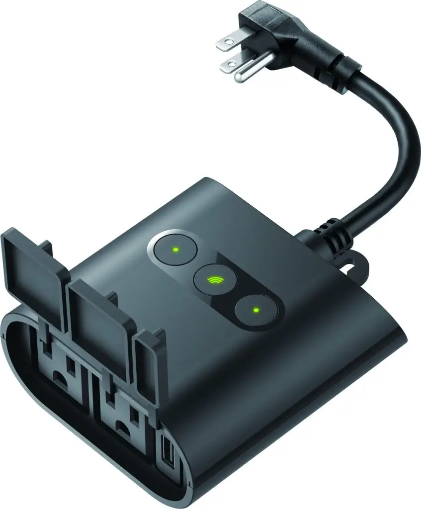
![]() DSP-W320 || Outdoor Wi-Fi Smart Plug
DSP-W320 || Outdoor Wi-Fi Smart Plug
![]() Quick Installation Guide
Quick Installation Guide
![]() Quick Installation Card
Quick Installation Card
If any of the above items are missing, please contact your reseller.
Note: Using an electrical outlet with a different voltage rating than recommended for this product will cause damage and void the warranty for this product.
Introduction
The D-Link DSP-W320 Outdoor Wi-Fi Smart Plug is a multi-purpose, compact, and easy-to-use device that allows you to control your home’s electric appliances, wherever you are. Scheduling provides a helpful way to save power while you’re at work or asleep, and the mydlink™ app provides an easy way to set up alerts, or power an appliance on or off.
System Requirements
| Network Requirements | • 802.11n/g wireless network • An Internet connection • A router connected to your broadband modem |
| mydlink™ App Requirements | • iPhone, iPad, Android smartphone or tablet (please refer to the mobile app’s store page to check whether your device is compatible) • Email account (for mydlink™ service registration) |
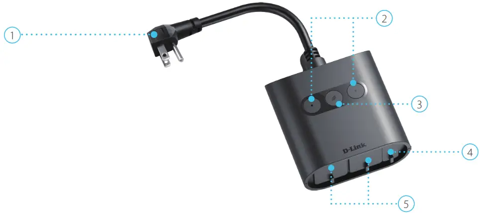
Hardware Overview
| 1 | Power Cord | Plugs into your wall outlet. |
| 2 | Power Buttons /Power Status LEDs | Press this button to switch on or off the individual power outlet. See LED Behavior on page 4 for LED behavior information. |
| 3 | Reset Button / System Status LED | Press and hold for this button until the System Status LED turns solid red to factory reset it. See LED Behavior on page 4 for LED behavior information. |
| 4 | USB Charging Port | Plugin a USB device that you wish to supply power to here. |
| 5 | Power Outlets | Connect your appliances, lamps, or other electronic devices you wish to control here. |
LED Behavior
| 1 | Power Status LEDs |  |
Switched on |
 |
Switched off | ||
| 2 | System Status LED |  |
Booting up / Resetting |
|
Connected to Wi-Fi and mydlink | ||
 |
Ready for set up / Disconnected | ||
 |
1 Firmware being upgraded |
Installation
Safety
Please read all of the safety and operating instructions before using your device:
- Do not open the device or attempt to repair or service it.
- Avoid plugging the device into a wall outlet that is not protected from weather changes.
- Make sure that the plug is inserted all the way into the wall outlet so that there is no exposed metal.
- Do not submerge the device in liquid or attempt to clean it with liquids or solvents. To clean the device, disconnect from the power outlet and use a damp towel.
Before you Begin
Plan the location of your device:
- Verify that your device is electrically rated to operate with the power available in your location.
- Connect the device into an electrical outlet that is not controlled by a wall switch. This will help you to avoid accidentally turning off power to the device.
- Be sure to plug it in to a grounded electrical outlet in order to help prevent electrical shock.
Wireless Installation Considerations
The DSP-W320 Outdoor Wi-Fi Smart Plug connects to your network using a wireless connection from virtually anywhere within the operating range of your wireless network. Keep in mind that the number, thickness, and location of walls, ceilings, or other objects that the wireless signals must pass through may limit the range. Typical ranges vary pending on the types of materials and background RF (radio frequency) noise in your home or business. The key to maximizing wireless range is to follow these basic guidelines:
- Keep the number of walls and ceilings between the product and other network devices to a minimum – each wall or ceiling can reduce your device’s range from 1 to 30 meters (3 to 90 feet). Position your devices so that the number of walls or ceilings is minimized.
- Be aware of the direct line between network devices. A wall that is 0.5 meters (1.5 feet) thick, at a 45-degree angle appears to be almost 1 meter (3 feet) thick. At a 2-degree angle, it looks over 14 meters (42 feet) thick. Position devices so that the signal will travel straight through a wall or ceiling (instead of at an angle) for better reception.
- Building materials make a difference. A solid metal door or aluminum studs may have a negative effect on range. Try to position access points, wireless routers, and computers o that the signal passes through drywall or open doorways. Materials and objects such as glass, steel, metal, walls with insulation, water (fish tanks), mirrors, file cabinets, brick, and concrete will degrade your wireless signal.
- Keep your product away at least 1 to 2 meters (3 to 6 feet) from electrical devices or appliances that generate RF noise.
- If you are using 2.4 GHz cordless phones or X-10 (wireless products such as ceiling fans, lights, and home security systems), your wireless connection may degrade dramatically or drop completely. Make sure your 2.4 GHz phone base is as far away from your wireless devices as possible. The base transmits a signal even if the phone is not in use.
mydlink App Device Setup
1.Download the mydlink app from the App Store (iOS) or Google Play (Android) by scanning the QR code.
Note: Ensure your device is connected wirelessly to the network that the DSP-W320 will be in.

![]()
2.Launch the mydlink app and create a new account or sign in to your existing account.
Note: On iOS devices, the app will pop up a permission request to send notifications.
3.After logging in, tap the Menu button![]() in the top-left corner.
in the top-left corner.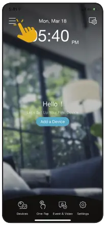
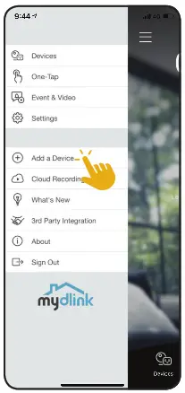
4.Select Add a Device.
Note: For Android devices, if you are asked about allowing the app to access your location, select Allow. Make sure location services and Bluetooth are turned on in your phone’s settings.
5.When asked to scan a Setup Code, press Next.
Scan the setup code on the Quick Installation Card.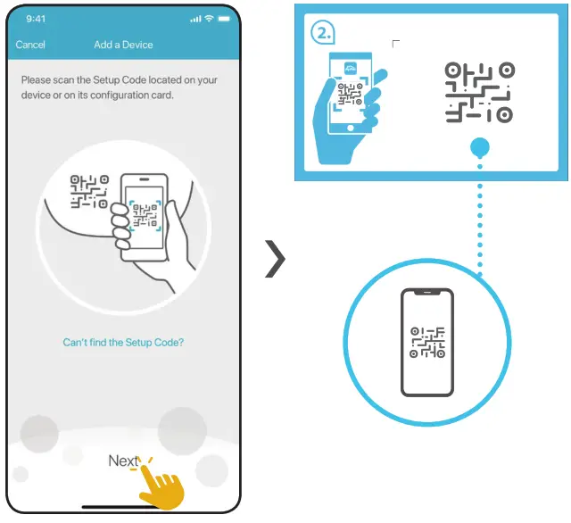 6.Follow the on-screen instructions to establish a connection to the device.
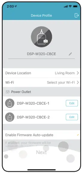
Choose the Device Location of your device and connect it to a Wi-Fi network. You can also configure the settings for each power outlet.
Tap Next when all items have been determined.
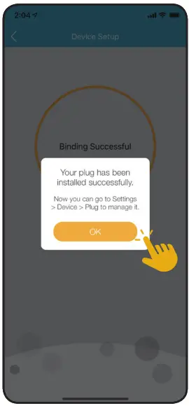
7.Tap OK to conclude the setup process.
Congratulations, your DSP-W320 Outdoor Wi-Fi Smart Plug is now ready to use!
Note: If you experience issues registering this plug with your mydlink account, or if you purchased an open box or resold unit, perform a hard reset by pressing and holding the Reset button on the device until the System Status LED turns red.
Using the mydlink App
Controlling Your Device
Note: Screenshots are representative only. The mydlink app is constantly being updated and so may appear different.
After setting up your DSP-W320 Outdoor Wi-Fi Smart Plug with a mydlink account in the mydlink app, you will be able to remotely access your smart plug through the app. After signing in to your mydlink account, you will see a screen similar to the following.
If you have previously checked the Add to shortcut option while installing the device, you will see a quick link to your device directly on the home screen. Tap the shortcut link to turn on or off your device.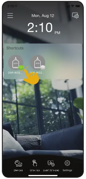
In the selected device group page, you can select the specific smart-controlled outlet in the carousel by tapping its icon.
Here you can turn off or on your outlet by tapping the![]() or
or![]() button. You can also tap that button from the home screen if you have previously checked the Add to shortcut option.
button. You can also tap that button from the home screen if you have previously checked the Add to shortcut option.
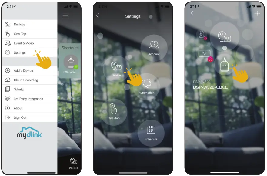
To access the settings for your DSP-W320 Outdoor Wi-Fi Smart Plug, tap ![]() > Settings > Device > navigate to your device on the carousel
> Settings > Device > navigate to your device on the carousel
Device
To access the device page:
• From the home page, tap ![]() > Settings > Device > navigate to your device on the carousel.
> Settings > Device > navigate to your device on the carousel.
| 1 | Device Photo | Tap to add a customized photo of this device. |
| 2 | Device Name | Tap to change the device’s name. |
| 3 | Device Location | Tap to change or add a new location for this device. |
| 4 | Wi-Fi | Displays the Wi-Fi network that the plug is currently connected to. To change it, please factory reset the device. |
| 5 | Power Outlet 1 | Tap to configure the settings for Power Outlet 1. You can add a customized photo of the device it’s plugged to and change the name for easy identification. |
| 6 | Power Outlet 2 | Tap to configure the settings for Power Outlet 2. You can add a customized photo of the device it’s plugged to and change the name for easy identification. |
| 7 | Firmware Update | Shows time of auto firmware update.Tap to enter the firmware update settings. You can choose the most suitable time for automatic updates as well as turn them off. |
| 8 | Current Firmware Version |
This displays the installed version of the firmware on your device. |
| 9 | Device ID | Identifies the device for support issues. |
| 10 | Remove Device | Tap this button to remove this device from your mydlink account. Note: To relink the device, reset it to factory default settings and run the setup process again. |

Troubleshooting
What do I do if my smart plug is not working properly?
Reset, then reinstall the smart plug. To reset your smart plug, press and hold the Reset button until the LED turns solid red.
During installation, ensure that:
- you have an Internet connection on your router
- your router’s Wi-Fi is on
- your mobile device is connected to the Internet
How can I use voice commands to control my smart plug?
The smart plug will work with both Amazon Alexa and Google Assistant. For setup instructions on these services, visit the following websites:
Alexa: https://www.dlink.com/en/alexa
The Google Assistant: https://www.dlink.com/en/google-assistant
How can I access my device remotely through the Internet?
In order to use your device remotely through the Internet using the mydlink app, you must register your device with a mydlink account. You can do this using the free mydlink app. Please go to Using the mydlink App on page 11 for more information.
Technical Specifications
| General | |
| Standards | •IEEE 802.11n/g • IEEE 802.15 BLE 4.1 |
| Security | •WPAAVPA2 |
| LED | •System status • Power status |
| Antennas | •One internal antenna |
| Buttons | •Power Button x 2 • Reset button |
| Functionality | |
| Support Functions | •Smart remote control • Countdown timer •Automation • Fumvvare Over-The-Air (FOTA) •Power scheduling • Works with the Google Assistant, Alexa, and IFM |
| Advanced Features | •mydlinr app for iOS and Android- devices |
| App Compatibility | •Please refer to the mobile app’s store page to check the compatibility of your device |
| Physical | |
| Dimensions (L x W x H) | •120.8x 98.0x 44.5 mm (4.76 x 3.86x 1.75 in) |
| Weight | •3369(11.85 oz) |
| Power Input | •2 x US (Type B) outlet: AC 120V/ 15 A • USB: DC 5V / 2.1 A |
| Input Frequency | •60 Hz |
| Power Consumption | •< 3W |
| Maximum Load | •1800W |
| Temperature | •Operating: -20 to 50 `C (-4 to 122 °F) • Storage: -20 to 70 °C (-4 to 1581) |
| Humidity | •Operating:20% to 80% non-condensing • Storage:5% to 95% non-condensing |
| Ingress Protection | •IP54 |
| Certifications | •FCC • RoHS •IC • UL 498A •cUL |
| Order Information | |
| Part Number | Description |
| DSP-W320 | Outdoor Wi-Fi Smart Plug |
Regulatory Information
Federal Communication Commission Interference Statement
This equipment has been tested and found to comply with the limits for a Class B digital device, pursuant to Part 15 of the FCC Rules. These limits are designed to provide reasonable protection against harmful interference in a residential installation. This equipment generates, uses and can radiate radio frequency energy and, if not installed and used in accordance with the instructions, may cause harmful interference to radio communications. However, there is no guarantee that interference will not occur in a particular installation. If this equipment does cause harmful interference to radio or television reception, which can be determined by turning the equipment off and on, the user is encouraged to try to correct the interference by one of the following measures:
– Reorient or relocate the receiving antenna.
– Increase the separation between the equipment and receiver.
– Connect the equipment into an outlet on a circuit different from that to which the receiver is connected.
– Consult the dealer or an experienced radio/TV technician for help.
Non-modifications Statement:
Any changes or modifications not expressly approved by the party responsible for compliance could void the user’s authority to operate this equipment.
Caution:
This device complies with Part 15 of the FCC Rules. Operation is subject to the following two conditions:
(1) This device may not cause harmful interference, and (2) this device must accept any interference received, including interference that may cause undesired operation.
This device and its antenna(s) must not be co-located or operating in conjunction with any other antenna or transmitter except in accordance with FCC multi-transmitter product procedures. For products available in the USA/Canada market, only channel 1~11 can be operated. Selection of other channels is not possible.
Note
The country code selection is for non-USA models only and is not available to all USA models. Per FCC regulations, all WiFi products marketed in the USA must be fixed to USA operational channels only.
IMPORTANT NOTICE:
FCC Radiation Exposure Statement
This equipment complies with FCC radiation exposure limits set forth for an uncontrolled environment. This equipment should be installed and operated with a minimum distance 20 cm between the radiator and your body. Innovation, Science and Economic Development Canada (ISED) Statement:
This Class B digital apparatus complies with Canadian ICES-003.
Cet appareil numérique de la classe B est conforme à la norme NMB-003 du Canada.
Innovation, Science and Economic Development Canada (ISED) Statement:
This device complies with ISED licence-exempt RSS standard(s). Operation is subject to the following two conditions:
(1) this device may not cause interference, and
(2) this device must accept any interference, including interference that may cause undesired operation of the device.
![]()
08/15/2019
Hardware: A1
Manual Version: 1.00
Preface
D-Link reserves the right to revise this publication and to make changes in the content hereof without obligation to notify any person or organization of such revisions or changes. Information in this document may become obsolete as our services and websites develop and change.
Manual Revisions
| Revision | Date | Description |
| 1.00 | 08/09/2016 | DCS-8300LH Revision A1 with
firmware version 1.00 |
Trademarks
D-Link and the D-Link logo are trademarks or registered trademarks of D-Link Corporation or its subsidiaries in the United States or other countries. All other company or product names mentioned herein are trademarks or registered trademarks of their respective companies. Copyright © 2016 D-Link Corporation.
All rights reserved. This publication may not be reproduced, in whole or in part, without prior expressed written permission from D-Link Corporation.
Product Overview
Package Contents
- DCS-8300LH Full HD 180-Degree Wi-Fi Network Camera
- Power Adapter
- Mounting Kit
- Quick Installation Guide
- Quick Install Card
Note: Using a power supply with a different voltage than the one included with your product will cause damage and void the warranty for this product. If any of the above items are missing, please contact your reseller.
System Requirements
- 802.11n/g router (a D-Link Cloud Router is recommended)
- A broadband Internet connection
- iPhone, iPad, Android, or Windows smartphone or tablet (please refer to the mobile app’s store page to check whether your device is compatible).
Introduction
The DCS-8300LH Full HD 180-Degree Wi-Fi Network Camera boasts a horizon-wide 180° lens that easily captures your entire room, wall-to-wall, in high-quality 1080p. Its rotatable head makes ceiling installations easy, and the built-in night vision and handy mobile app empower you with knowing exactly what is happening, day or night. The DCS-8300LH comes with remote monitoring and motion detection features, and is compatible with the mydlink Home ecosystem so you can automate and manage and your home or office from anywhere.
Features
180° Wide Angle Lens
The DCS-8300LH provides whole-room coverage with a 180° wide angle lens, eliminating the need for multiple cameras to cover a single room. Built-in dewarping technology automatically corrects the image for you.
1080p Full HD Video
The 1080p Full HD sensor provides crisp detail and clarity for high-quality snapshots and video.
Comprehensive Day/Night Surveillance
The built-in infrared LEDs enable night time viewing of up to 16 feet (5 meters), and the PIR sensor detects nearby motion even in complete darkness. The microSD card slot allows the camera to record snapshots and video directly to onboard storage for a complete surveillance solution.
Wireless N Connectivity
The DCS-8300LH uses high-speed Wireless N to connect to your wireless router, and is compatible with 802.11n/g.
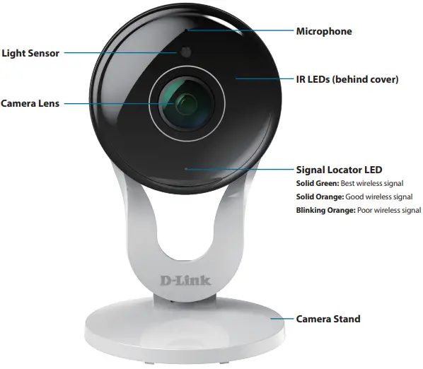
Hardware Overview
Front View
Rear View
Installation
Please follow the instructions below to set up your Full HD 180-Degree Wi-Fi Network Camera.
Step 1:
On your mobile device, download mydlink Home by going to mydlinkhomeapp.dlink.com, or by searching for mydlink Home in the iTunes App Store or Google Play.
Step 2:
Launch the mydlink Home app and create a new account or sign in to your existing account.
iOS: If you are asked about allowing the app to access your location, select Allow. Android: Make sure location services are turned on in your phone’s settings.
Step 3
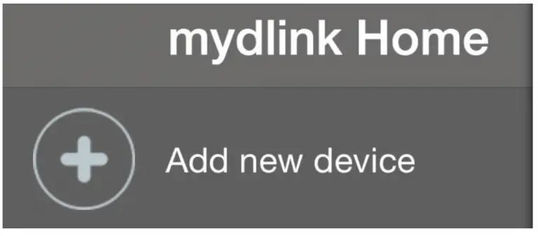
After logging in, tap the Settings 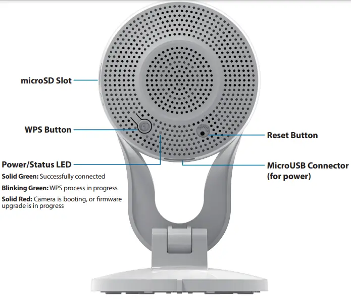 icon in the top-left corner, select Add New Device, and follow the instructions.
When you are asked to scan a QR code, use the code on the Quick Install Card in your package, or on the label attached to your device.
Congratulations, your Full HD 180-Degree Wi-Fi Network Camera is now ready to use!
Be sure to check the dlink.com/mydlinkhomehelp website periodically for the latest firmware updates to keep your product secure and up to date with the latest features.
Note: If you experience issues registering this camera with your account, or if you purchased an open box or resold unit, perform a hard reset by pressing and holding the reset button on the device for 10 seconds while the device is powered on. If you are returning the device to the place of purchase, please perform the hard reset procedure to clear the device of any personal data.

Mounting the Camera
To mount your camera on a wall or ceiling, please follow the steps below. It is recommended that you configure the camera before mounting.
Step 1
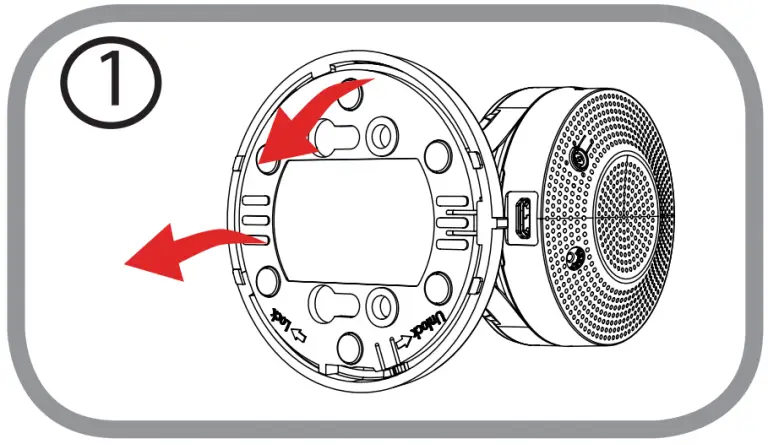
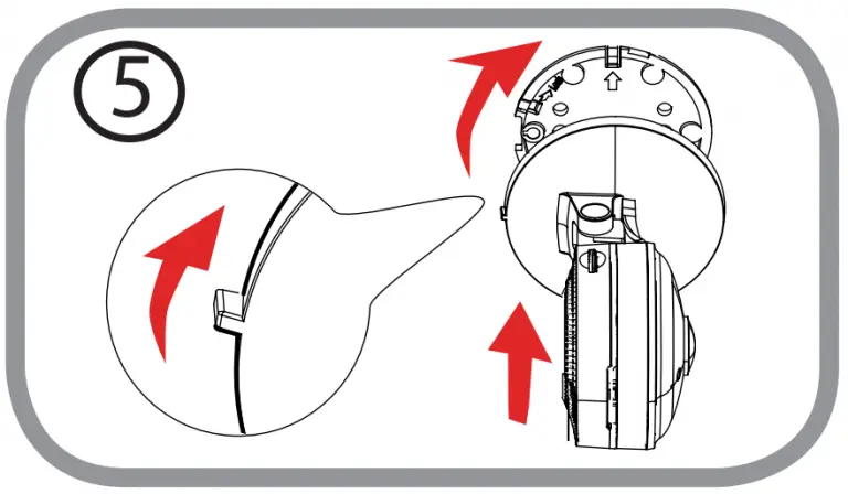
Rotate the baseplate counter-clockwise and remove it.
Step 2
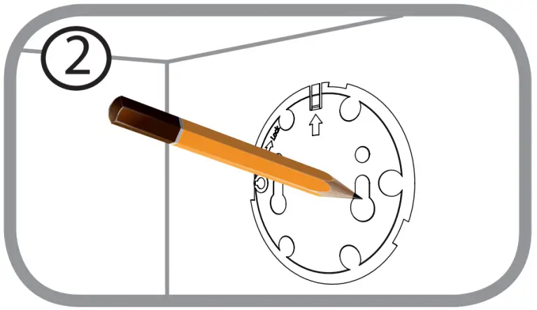
Place the baseplate where you want to position the camera and use a pencil to mark the holes. You can use the lower holes for a removable installation, or the top holes for a fixed one. Make sure that the arrow on the baseplate is pointing up.
Step 3
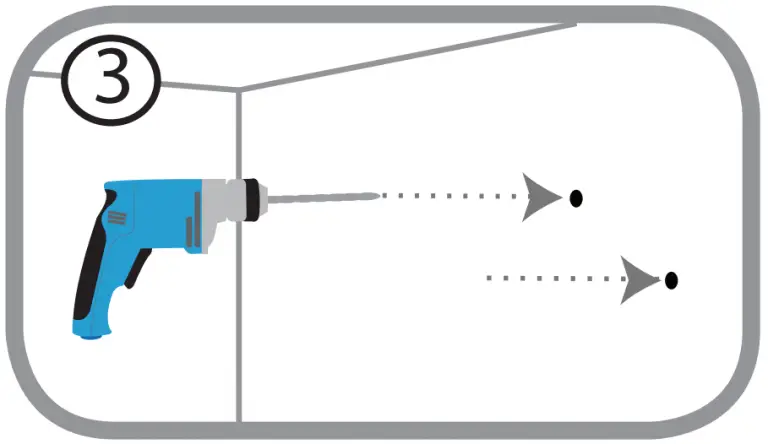
Depending on the material of the wall or ceiling, use proper tools to drill holes 25 mm deep with a 6 mm drill bit where you marked. If the wall is made out of concrete, drill the holes first, then insert the plastic anchors to support the screws.
Step 4
Place the baseplate over the holes that are in the wall. Make sure to align the baseplate holes with the holes in the wall. Use the supplied screws to attach the baseplate to the surface of the wall.
Step 5
Place the camera over the baseplate with the alignment nub pointing left, then attach the camera by rotating it until the alignment nub points up.

Step 6
Adjust the angle and rotation of the camera as desired. You can also rotate the camera on the baseplate about 45° to the right or left
Technical Specifications
| Camera | ||
| Camera Hardware Profile | •1/3″ Megapixel progressive CMOS sensor •Minimum illumination: •Color mode:0.5 lux •B/W mode (LEDs off 1:0.1 lux •B/W mode (LEDs on): 0 linc •Minimum object distance 30 cm •Lens focal length:1.7 mm |
•Aperture: F2.5 •Angle of view (16:9): •0-1) 180° •(V) 86° •(D) 180° •Stand angle: -19 to 90° |
| image Features | •Configurable image size, quality, frame rate, and bit rate •Wide Dynamic Range (VVDR) •3D filtering •Time stamp and text overlays |
•Configurable motion detection windows •Configurable privacy mask zones •Configurable exposure time, brightness, saturation, contrast, sharpness. |
| Video Compression | •I1264 | •JPEG for still images |
| Video Resolution | •1080p at up to 15 fps | •720p, 360p at up to 30 fps |
| Audio Support | •6.711 p-law | |
| Connectivity | •802.11 rUg/b wireless with WPA/WPA2 encryption •Operates on 2.4 GHz band |
•Maximum data rate of 155 MBps (PHY rate) ‘ •micro SD/SDHC/SDXC card Slot, accepts cards up to 128 GB |
| Network | ||
| Network Protocols | •IPv6, IPv4, ARP, TCP, UDP, ICMP •DHCP client •NIP client (D-Link) •DNS client |
•HTTP server •Bonjour •UPnP port forwarding |
| Security | •Password authentication | •HTTP and RTSP digest encryption |
| System Integration | ||
| Event Management | •Motion detection •Sound level detection |
•Push notification when motion/sound is detected •Motion/sound triggered recording |
| Mobile Support | •myd link Home app for i Phone, iPad, iPod Touch, and Android |
Appendix A: Technical Specifications
| General | ||
| Dimensions | •109.6 x 66.0 x 66.0 mm (4.3 x 2.4 x 2.4 inches) ± 5% | |
| Weight | •105 grams (3.7 ounces) ± 5% | |
| Power Adapter | •Input: 100 to 240 V AC, 50/60 Hz | •Output: 5 V DC 1.2 A |
| Power Consumption | •4.5 watts ± 5% | |
| Temperature | •Operating: 0 to 40 °C (32 to 104 °F) | •Storage: -20 to 70 °C (-4 to 158 °F) |
| Humidity | •Operating: 20% to 80% non-condensing | •Storage: 5% to 95% non-condensing |
| Certifications | •CE •CE LVD |
•FCC •ICES |
| Dimensions Diagram | 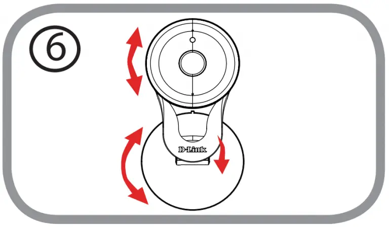  |
34 . 4 k |
Regulatory Information
Federal Communication Commission Interference Statement
This equipment has been tested and found to comply with the limits for a Class B digital device, pursuant to Part 15 of the FCC Rules. These limits are designed to provide reasonable protection against harmful interference in a residential installation. This equipment generates, uses and can radiate radio frequency energy and, if not installed and used in accordance with the instructions, may cause harmful interference to radio communications. However, there is no guarantee that interference will not occur in a particular installation. If this equipment does cause harmful interference to radio or television reception, which can be determined by turning the equipment off and on, the user is encouraged to try to correct the interference by one of the following measures:
- Reorient or relocate the receiving antenna.
- Increase the separation between the equipment and receiver.
- Connect the equipment into an outlet on a circuit different from that to which the receiver is connected.
- Consult the dealer or an experienced radio/TV technician for help.
Non-modifications Statement:
Any changes or modifications not expressly approved by the party responsible for compliance could void the user’s authority to operate this equipment
Caution
This device complies with Part 15 of the FCC Rules. Operation is subject to the following two conditions:
- This device may not cause harmful interference, and (2) this device must accept any interference received, including interference that may cause undesired operation.
This device and its antenna(s) must not be co-located or operating in conjunction with any other antenna or transmitter except in accordance with FCC multi-transmitter product procedures. For product available in the USA/Canada market, only channel 1~11 can be operated. Selection of other channels is not possible.
Note
The country code selection is for non-USA models only and is not available to all USA models. Per FCC regulations, all WiFi product marketed in the USA must be fixed to USA operational channels only.
IMPORTANT NOTICE:
FCC Radiation Exposure Statement
This equipment complies with FCC radiation exposure limits set forth for an uncontrolled environment. This equipment should be installed and operated with minimum distance 20 cm between the radiator and your body.
Industry Canada Statement:
This device complies with Industry Canada licence-exempt RSS standard(s). Operation is subject to the following two conditions:
- this device may not cause interference, and
- this device must accept any interference, including interference that may cause undesired operation of the device.
Radiation Exposure Statement
This equipment complies with IC radiation exposure limits set forth for an uncontrolled environment. This equipment should be installed and operated with minimum distance 20 cm between the radiator and your body.
European Union:
Notice of Wireless Radio LAN Usage in The European Community (For Wireless Product Only):
- At the time of writing this addendum, some countries such as Italy, Greece, Portugal, and Spain have not allowed operation of radio devices in the 5 GHz bands, although operation of 2.4 GHz radio devices is allowed. Please check with your local authority to confirm.
- This device is restricted to indoor use when operated in the European Community using channels in the 5.15-5.35 GHz band to reduce the potential for interference.
- This device is a 2.4 GHz wideband transmission system (transceiver), intended for use in all EU member states and EFTA countries, except in France where restrictive use applies.
- This device may not be used for setting up outdoor radio links in France and in some areas the RF output power may be limited to 10 mW EIRP in the frequency range of 2454 –2483.5 MHz. For detailed information the end-user should contact the national spectrum authority in France.
This equipment may be operated in AL, AD, BE, BG, DK, DE, FI, FR, GR, GW, IS, IT, HR, LI, LU, MT, MK, MD, MC, NL, NO, AT, OL, PT, RO, SM, SE, RS, SK, ES, CI, HU, CY.
Usage Notes:
- To remain in conformance with European National spectrum usage regulations, frequency and channel limitations will be applied on the products according to the country where the equipment will be deployed.
- This device is restricted from functioning in Ad-hoc mode while operating in 5 GHz. Ad-hoc mode is direct peer-to-peer communication between two client devices without an Access Point.
- Access points will support DFS (Dynamic Frequency Selection) and TPC (Transmit Power Control) functionality as required when operating in 5 GHz within the EU.
- The full text of this device’s EU Declaration of Conformity (DoC) and firmware are available at http://www.dlink.com.
Appendix B: Regulatory Information
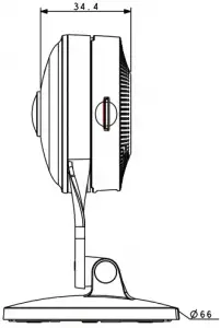
| 2.4 GHz Wireless Frequency and Channel Operation in EEC Countries: | ||
| Region | Frequency Band | Max output power (EIRP) |
| Metropolitan | 2400 – 2454 MHz | 100 mW |
| Guadeloupe, Martinique, St Pierre et Miquelon, Mayotte | 2454 – 2483.5 MHz | 100 mW indoor, 10 mW outdoor |
| Reunion et Guyane | 2400 – 2483.5 MHz | 100 mW |
| Rest of EU community | 2420 – 2483.5 MHz | 100 mW |
| RED 2014/53/EU | |||
| WLAN 2.4 – 2.4835 GHz | |||
| IEEE 802.11b/g/n | |||
| Spectrum Regulation | MHz, Europa (ETSI) | max. EIRP Innenbereich | max. EIRP Außenbereich |
| Europa | 2400 – 2483.5 MHz | 100 mW | 100 mW |
| Frankreich | 2400 – 2454 MHz | 100 mW | 100 mW |
| 2454 – 2483.5 MHz | 100 mW | 10 mW | |
Warning Statement:
The power outlet should be near the device and easily accessible
Disposing of and Recycling Your Product

This symbol on the product or packaging means that according to local laws and regulations this product should be not be disposed
of in household waste but sent for recycling. Please take it to a collection point designated by your local authorities once it has
reached the end of its life, some will accept products for free. By recycling the product and its packaging in this manner you help to
conserve the environment and protect human health.