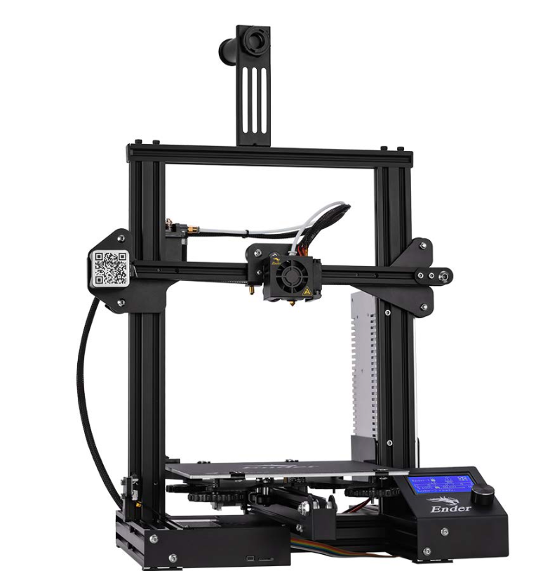
Creality Ender-3 3D Printer
Dear Consumers,
Thank you for choosing our products. For the best experience, please read the instructions before operating the Printer. Our teams will always be ready to render you the best services. Please contact us by phone number or e-mail address provided at the end when you encounter any problem with the Printer.
For a better experience in using our product, you can also learn how to use the Printer in the following ways:
View the accompanied instructions and videos in the TF Card.
Visit our official website www.creality.com to find relevant software/hardware information, contact details and operation and maintenance instructions.
A Notes
Product introduction
Spare parts
B Assemble the 3D printer
C Use the 3D printer
Start printing
Wire connection
Troubleshooting
NOTES
- Do not use the printer any way other than described herein in order to avoid personal injury or property damage.
- Do not place the printer near any heat source or flammable or explosive objects. We suggest placing it in a well-ventilated, low-dust environment.
- Do not expose the printer to violent vibration or any unstable environment, as this may cause poor print quality.
- Before using experimental or exotic filaments, we suggest using standard filaments such as ABS or PLA to calibrate and test the machine.
- Do not use any other power cable except the one supplied. Always use a grounded three-prong power outlet.
- Do not touch the nozzle or printing surface during operation as they may be hot. Keep hands away from machine while in use to avoid burns or personal injury.
- Do not wear gloves or loose clothing when operating the printer. Such cloths may become tangled in the printers moving parts leading to burns, possible bodily injury, or printer damage.
- When cleaning debris from the printer hotend, always use the provided tools. Do not touch the nozzle directly when heated. This can cause personal injury.
- Clean the printer frequently. Always turn the power off when cleaning, and wipe with a dry cloth to remove dust, adhered printing plastics or any other material off the frame, guide rails, or wheels. Use glass cleaner or isopropyl alcohol to clean the print surface before every print for consistent results.
- Children under 10 years of age should not use the printer without supervision.
- This machine is equipped with a security protection mechanism. Do not manually move the nozzle and printing platform mechanism manually while booting up, otherwise the device will automatically power off for safety.
- Users shall comply with related nation and region’s laws, regulations and ethical codes where the equipment or produced prints by it is used, and users of our product shall not use aforesaid products to print any end-use products,objects,parts or components or any other physical prints that violate the national or regional laws, regulations and ethical codes where herein referred product and produced prints by it is located.
Product introduction
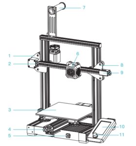
- XE-axis kit
- X-axis limit switch
- Print platform
- Y-axis
- Toolbox
- Extruded kit!
- Material rack and spool holder
- Z-axis passive block
- X-axis tensioner
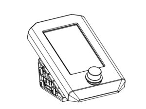
- Screen
- Knob switch
- Machine base
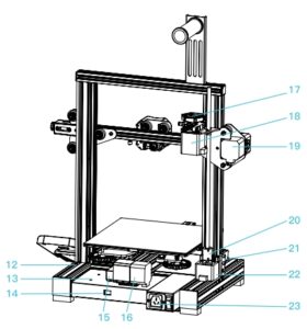
- Power supply
- Voltage regulator
- Y-axis limit switch
- Y-axis motor
- Indication knob!
- E-axis motor
- X-axis motor
- Coupling
- Z-axis limit switch
- Z-axis motor
- Power switch and socket
Equipment parameters
Basic Parameters
Model: Ender-3 V2
Print size: 220*220*250mm
Forming technology: FDM
Number of nozzle: 1
Layer thickness: 0.lmm-0.4mm
Nozzle diameter: Standard
X-/ axis precision: ±0.lmm
Filament: ¢1.75mm PLA
File format: STL/OBJ/AMF
Working mode: Memory card offline printing or on line printing
Compatible slicing software: 3D Creator Slicer, Repetier-Host, Cura, Simplify3D
Power specification: Input: AC 115-230V 50/60Hz Output: DC 24V
Total power: 350W
Hotbed temperature: <l00’C
Nozzle temperature: <250’C
Resume printing function: Yes
Filament sensor: No
Dual z-axis screws: No
Language switch: English
Computer operating system: Windows XP/Vista/7 /10/MAC/Linux
Print speed: <180mm/s, 30-60mm/s normally
Spare parts
- Printer base x 1

- Display kit x 1
- Extruded kit x 1
- Z-axis passive block x 1
- X-axis tensioner x 1
- Z-axis motor kit x 1
- Z-axis limit switch kit x 1
- XE axis kit x l

- Z-axis profile(left) x 1
- Z-axis profile(right) x 1
- Gantry profile x 1
- X-axis profile x 1
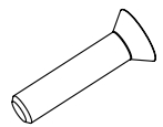
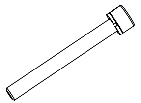
- T-type screw x 1
 Accessory tool list l!c:!f!t-L~m¥
 - Material rack
- Material pipe and nut
- 2020 profile cover x 2
- Synchronous belt x 1

- Metal blade x 1

- Diagonal pliers x 1

- Cable tie x l

- Needle x l

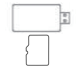
- Storage card and card reader x 1
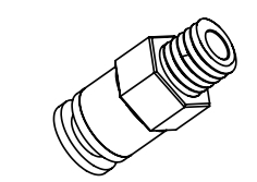
- Pneumatic joint x 2
- Power cable x l

- Wrenches and screwdrivers x 1

- Blue line claw x 2

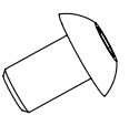
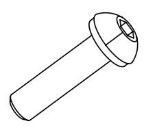
- Hexagon socket flat round head screw MSX8 x 2
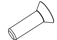
- Hexagon socket countersunk head screw M4Xl8 x 2
- Hexagon socket head spring washer combination screw M5X25 x 5
- MST nuts x2
- Hexagon socket head spring washer combination screw M5X45 x 5
- Hexagon socket flat round head spring washer combination screw M4Xl6 x 5
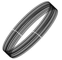
- Filament xl
- Indication knob x 1
- Hexagon socket countersunk head screw (black) M4Xl4 x 1
- Nozzle x l
Installation of Z-axis limit switch kit and Z-axis profiles
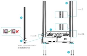
Tip: Step: Put the endstops sensor on Z-axis (left) like the picture above. Then use the four pieces screw MSX45 to fix Z-axis with the base.
Printer base x 1
Z-axis profile(left) x 1
Z-axis profile(right) x 1
Z-axis ~mil switch kit x 1
31. Hexagon socket head spring washer combination screw M5X45 x 4
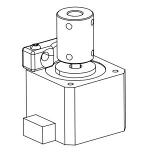
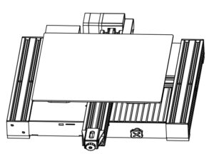
Install Z-axis motor kit and t-type screw
Tip: Steps: Lock the T-shaped screw rod on the Z-axis motor component, and then use two M4Xl8 screws to slightly lock the Z-axis motor component on the profile (as shown above).
13. Hype screw x 1
6. Z-axis motor kit x 1
28. Hexagon socket countersunk head screw M4x18 x 2
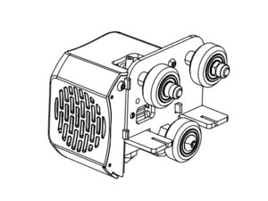
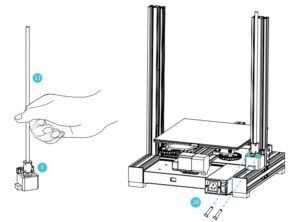
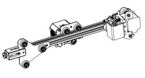
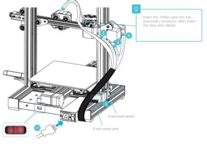
Install pneumatic joint, XE-axis kit and synchronous belt
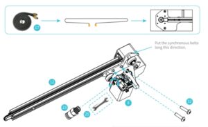
Tip: Step: Tighten the tube connector by open end wrench. And fix the XE axis kit with two pieces M4*16 screw. Put the timing belt through the XE-axis kit with direction same as the picture.
8. XE axis kit x l
12. X-axis profile x 1
23. Pneumatic joint x l
32. Hexagon socket flat round head spring washer combination screw M4X16 x 2
17. Synchronous belt x 1
25. Open-end wrench x 1

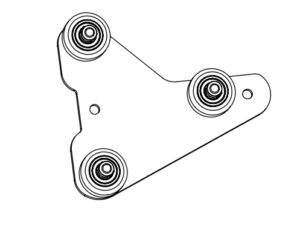
4. Install extrusion kit, Z-axis passive block
Tip:Steps: Put the synchronous belt into the profile along the v-wheel of the extrusion kit. When pushing it into the middle, as shown in the figure; lock the z-axis passive block with one M4X 16 screw.
3. Extruded kit x 1
4. Z-axis passive block x 1
32. Hexagon socket flat round head spring washer combination screw M4Xl6 x 1
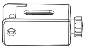
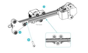
5. Install X-axis Tensioner
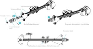
Tip:Steps: Insert the timing belt into the tensioner block, and put it into the X-axis tensioner together with the timing belt, tighten it with a plastic hand screw nut, and then lock it with round head M4Xl6 and countersunk head M4Xl4 screws both sides of the Z axis passive block.
5. X-axis tensioner x 1
32. Hexagon socket flat round head spring washer combination screw M4Xl6 x 1
35. Hexagon socket countersunk head screw (black) M4Xl4 x 1
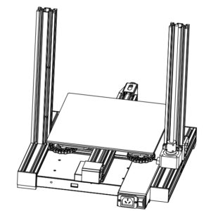
6. Install Z-axis moving kit
Tip: Steps: Make the Z-axis moving kit insert the two ends of the z-axis profile along V-wheel on both sides. As shown in the figure above.
Take the fifth step: assembled component
Take the second step: assembled components
7. Install the gantry profile,display kit
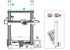
Tip: Step: Install the upper frame of the gantry structurewith 4 pieces of MSX25 screw. Use an Allen wrench to lock the screen kit onto the machine with the left side four screws.
11. Gantry profile x 1
2. Display kit x 1
29. Hexagon socket head spring washer combination screw M5X25 x 4
8. Install material rack, gantry cover and indication knob
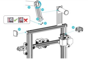
Tip: Steps: Put flat round head M5X8 and MST screws into the material rack(as shown), place the spool holder on the rack and fix on the profile with screws(as shown); Put the indication knob on the motor shaft and then place the 2020 profile cover on both side.
14. Material rack x 1
15. Material pipe and nut x 1
16. 2020 profile cover x 2
27. Hexagon socket flat round head screw M5X8 x 2
30. MST nut x2
34. Indication knob x 1
Wire connection
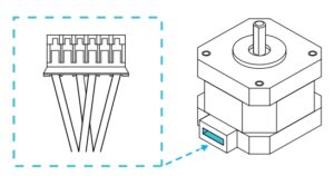
Connect X, E, Z-axis stepper motors according to the yellow label on the 6pin (4 wires) port
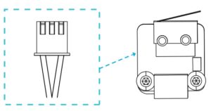
Connect X, Z-axis limit switches according to the yellow label on the 3pin (2wires) port
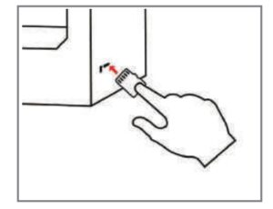
Plug in the power cord (as shown) and toggle the switch to turn on the power
24. Power cable x 1
26. Blue wire clip x l
X, E, Z-axis motor port
X, Z-axis limit switch
10. Preheat
Method 1

Note: The UI information is only for reference, the actual UI may be different.
Method 2

Load the filament
- When waiting for the temperature to rise, please hang the filaments on the material rack.
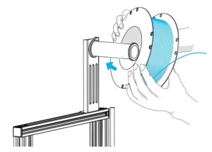
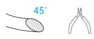
NOTE:For better printing, the end of filament Is as shown In t he figure.
- Press the extrusion spring and insert the filament until the nozzle along the extrusion. When the temperature is up to the target temperature, the filament will come out of the nozzle,nozzle, and complete loading the filament.
Note: Replace the filament:
- If no filament in the nozzle, cut the filament at the extrude, put the new filament into the tube, and until the filament arrives on the feeding tube.
- If filament in the nozzle, heat up the nozzle to 185°+, draw out the filament, and then replace the filament according to step 1.
- If replace the filament during the printing process.adjust the printing speed to 10%, and then replace the filament according to step 2.
12. Start printing
Please level the platform according to the video in storage card. Bad leveling will cause clogging or break of nozzle.
5. Generate G-code, and save the geode file to TF card.

6. lnsert the TF card ➔ press the knob ➔ select the menu
➔ the file to be printed.
Warning: File names must be Latin letters or numbers, not Chinese characters or other special symbols.
Tip: Notes: For details on the software instructions, please refer
to the slicing software manual in the memory card!

Wiring connection
Troubleshooting

Is the Ender 3 3D printer worth it?
The Creality Ender 3 is an excellent option for beginners or makers on a budget. While this 3D printer does have its flaws, the affordability makes it a worthwhile investment
What can you print with a Creality Ender 3?
However, as it is not an all-metal hot-end, so the temperature is limited to 240°C because of the use of PTFE tubing and the quality of the components it’s made of. Otherwise, Creality Ender-3 3d printer is supposed to quite versatile in printing with a variety of plastics, such as PLA, ABS, TPU, and even PETG.
Do 3D printers use a lot of electricity?
Ordinary 3D printers do not use much electricity, only about 50-150 Watts while printing. This is about the same as one or two incandescent light bulbs. There are many different 3D printers and print settings available, however, so for a more accurate number you need to make some calculations or measurements.
What’s the difference between Ender 3 and Ender 3 Pro?
Ender-3 Pro has a detachable magnetic heated bed and improvements to the Y-axis to achieve a better print quality, which makes the Ender-3 Pro more expensive. The price is under $300. Compared to Creality Ender-3, it’s more expensive.
Can I make money 3D printing?
Yes, you can make money with a 3D printer. And there are a lot of ways that you can do it, whether that’s selling 3D printed items, digital goods, or even offering a 3D printing service in your local area
What size table do I need for Ender 3?
What size table do I need for the Ender 3? The Ender 3 has a footprint of 440 x 410 mm, so you will need a 3D printer table that is at least this size. If you want to be able to move the 3D printer around on the table, you may want to consider a table that is larger.
How do I connect my Ender 3 to my computer?
This step is simple: connect the mini USB end to your Ender 3 and the USB end to your computer. When you plug it into your computer, it will display a message and make a noise to indicate that it has detected your 3D printer. Typically, it will state that it is installing the drivers. Allow it to do so for a while
How tall can you print on an Ender 3?
Swap the firmware: By default, Creality’s Ender 3 firmware only allows you to use 220 x 220 mm of print surface.
Does the Ender 3 have WiFi?
The Ender 3, Pro, and V2 can all support ba Wi-Fi connection, though there are a few different options, which we’ll look at in the following sections. Let’s get started!
Can I connect my phone to my Ender 3?
Connecting your Creality Ender 3 V2 to WiFi using BuildBee Desktop allows you to connect via USB and get started quickly. If you need to head out, you can monitor the progress of your prints by using the BuildBee web app or Android app on your smartphone
How do I transfer files to Ender 3?
Until you see the save to file button at the bottom right corner of your slicer. Next you’re going to plug in your micro sd card into your adapter such that you can connect it to your pc.
What software does Creality use?
Creality Ender 3 is a fork of Cura, meaning it was based on older versions of Cura with some of Creality’s own developments added to the software. Creality Slicer has support for all Creality 3D printers and pretty well-tuned profiles for each one, including the Ender 3 models.
]]>
Notes
- Do not use the printer any way other than described herein in order to avoid personal injury or property damage.
- Do not place the printer near any heat source or flammable or explosive objects. We suggest placing it in a well- ventilated, low- dust environment.
- Do not expose the printer to violent vibration or any unstable environment, as this may cause poor print quality.
- Before using experimental or exotic filaments , we suggest using standard filaments such as PLA to calibrate and test the machine.
- Do not use any other power c able exc ept the one s upplied. Always use a grounded three- prong power outlet.
- Do not touch the nozzle or printing surface during operation as they may be hot. Keep hands away from machine while in use to avoid burns or personal injury.
- Do not wear gloves or loose clothing when operating the printer. Such cloths may become tangled in the printers moving parts leading to burns, possible bodily injury, or printer damage.
- When cleaning debris from the printer hotend, always use the provided tools. Do not touch the nozzle directly when heated. This can cause personal injury.
- Clean the printer frequently. Always turn the power off when cleaning, and wipe with a dry cloth to remove dust, adhered printing plastics or any other material off the frame, guide rails, or wheels . Use glass cleaner or isopropyl alcohol to clean the print surface before every print for consistent results.
- Children under 10 years of age should not use the printer without supervision
- This machine is equipped with a security protection mechanism. Do not manually move the nozzle and printing platform mechanism manually while booting up, otherwise the device will automatically power off for safety.
1 .Introduction
2.General List
♦ Tool List
3.Device lnstalltion

4.Cable Connection
6.Loading Filament
7.Bed Leveling
♦ Automatic leveling

8.Software Installation
9.First Printing

10.Circuit Wiring
After- Sales Service
Service
The printer can be returned within seven days, 15 days replacement, one year warranty, lifetime maintenance.
Replacement Requirement
- The appearance of the product is intact, without damage, scratches, smudges, cracks, deformation, etc.;
- Machine parts, tools and others are complete;
- Provide a complete and valid purchase invoice and warranty, product number should be the same.
Warranty Coverage
- The following accessories are not included in the warranty coverage if
they are not damaged by transportation: platform sticker; platform
forming plate; acrylic cover; card reader and TF card; platform glass; USB cable; filament; rack and tools,etc. - Profile: Before we deliver the goods, we will do the machine test, so maybe there will be light scratch, or due to long-distance transportation, which scratch the profile a little bit. in the premise of not affecting the normal use, in principle, not within the scope of warranty;
- Nozzle assembly (nozzle, heating block, throat pipe,heat sink, Teflon tube, etc.) warranty period is 3 months, if it is damage after the warranty expires, you need to purchase another one;
- Motherboard, LCD display, power supp~, hot bed,warranty period is 1 2 months, if there are quality problems, you can get free maintenance; over the warranty period, can be sent back to the original factory maintenance, the users need to bear the return shipping and maintenance costs;
- Not included in warranty coverage:
(1) It is not possible to provide an effective after-sales service card or serial number;
(2) The whole machine and components exceed the warranty period;
(3) Equipment failure or damage caused by unauthorized modification of the equipment (private modification includes: 1. modification of the nozzle assembly; 2. modification of the machine structure; 3. use of third-party components; 4. use of third-party firmware procedures or change the original Factory firmware program, etc.);
(4) Equipment failure or damage due to incorrect installation and use;
(5) Equipment failure or damage caused by the use of the equipment in a working environment not specified by the product;
(6) Equipment failure or damage due improper use (beyond workload, etc.) or maintenance (moisture, etc.);
(7) Equipment failure or damage due to the use of other branded components or low quality consumables.
Statement:
For better highlighting the function and effectiveness of 3d printer and promoting the development of global market economic, strengthening the user self-discipline of 3d industry and establishing a good image of 3d printing, since Creality 3d printer have passed all kinds of authorized product certificates and quality management system.hereby we declare that it is strictly forbidden to use our printer to print any products or equipment that are in violation of the specific country and regions legislation.
]]>View Fullscreen
CREALITY
3D Printer User Manual
( CR-10 V3)
V1 .0
Content El~
Dear Consumers, Thank you for choosing our products. For the best experience, please read the instructions before operating the Printer. Our teams will always be ready to render you the best services. Please contact us via the phone number or e-mail address provided at the end when you encounter any problem with the Printer. For a better experience in using our product, you can also learn how to use the Printer in the following ways: View the accompanied instructions and videos in the storage card. Visit our official website www.creality.com to find relevant software/hardware information, contactdetails and operation and maintenance instructions.
~11Jl(S<Jfrj’®::C:i!/llP : ~lt-J/fzJ’i’, ile/llfrU/:ll.=i!B<lF6/,onT/file/ll7J1′:, ii!l1ftEile/llLITTfff@li!IJi~~iJl,SJl’tl, #Ff!l:iilssi!/,SJl’tlB”it~’1’i!:!fi!lHl’o frU’®::C:i!im!,!.Sstt<U;Jtiinltmi!ifLmlB”l~~~otrile/lli1f¥’11:Jci1′:~iUH2,JcJl’J!i, illl:iilssi!/, S)l’tl~PP!imi!B”i~ii’i, ill!ffi~ttil’Ji!Hj~J.’~o n T1t,m~l!a:Htilif;$c~tttm S<Ji”-61,, 1mESoJ”Y-M”Y-~JJ’i’l’.Rl!Xiliii!ildemm: IIM/lile/lli!/,S)l: imoJ “y_ffl’¥ii1!-tPJ!’UUt§*ile/lli!/,SJlEl.t’lli)Jjo frU’®::C:i!!1llRJ :www.cxsw3d.com 1&’loJml’!MU/:ll::C:i!!1llRlsl-tM§*~~111′,lll<~7J’i”., iliii!lH’, ili&i~~~i/Li,!,o
Notes
Assemble the 3D Printer
Use the 3D Printer
f:fffl 3D HEP1′!1
Level the Heated Bed
i/al,:P:
Load Filament
~Jlq
Start Printing
:iHilJJEP
‘ ,——————————————————————————
l.Do not use the printer any way other than described herein in order to avoid personal injury or property damage.
‘
2.Do not place the printer near any heat source or flammable or explosive objects. We suggest placing it in a well-ventilated, low-dust environment.
3.Do not expose the printer to violent vibration or any unstable environment, as this may cause poor print quality.
4.Before using experimental or exotic filaments, we suggest using standard filaments such as ABS or PLA to calibrate and test the machine.
5.Do not use any other power cable except the one supplied. Always use a grounded three-prong power outlet.
6.Do not touch the nozzle or printing surface during operation as they may be hot. Keep hands away from machine while in use to avoid burns or personal injury.
7.Do not wear gloves or loose clothing when operating the printer. Such cloths may become tangled in the printers moving parts leading to burns, possible bodily injury, or printer darn age.
8.When cleaning debris from the printer hotend, always use the provided tools. Do not touch the nozzle directly when heated. This can cause personal injury.
9.Clean the printer frequently. Always turn the power off when cleaning, and wipe with a dry cloth to remove dust, adhered printing plastics or any other material off the frame, guide rails, or
wheels. Use glass cleaner or isopropyl alcohol to clean the print surface before every print for consistent results.
10.Children under 10 years of age should not use the printer without supervision.
11.This machine is equipped with a security protection mechanism. Do not manually move the nozzle and printing platform mechanism manually while booting up, otherwise the device will
automatically power off for safety.
12.Users shall comply with related nation and region’s laws, regulations and ethical codes where the equipment or produced prints by it is used, and users of our product shall not use
aforesaid products to print any end-use products,objects,parts or components or any other physical prints that violate the national or regional laws, regulations and ethical codes where herein
referred product and produced prints by it is located.
‘,—————————————————————————————————————————————————————-‘,
I
1, i.~?J.J’ii’ii’tfffoJ-fleffli.)/,Bjjq:i;~~:li’i’il&BkJJJ5!*1lem*tfl, lM:9’c@-5xBkJ~$lAs{95~;f
m1f”tvl~;
2, i.~mi~*tflm:’l!l’i’±~m,~~!to/J£!l!Gi’@ii?i5)j’11ili, i.~i~*tflm:’l!l’i’.±JfflJx, ~jj;jj'(,:J>~BkJifiipg;
3, J.~mi~HEPtflm:’l!l’i’±[email protected];fl:!l!Gtf;let{tlfff&)EilkJif±ipg, tfl~~ii;/J~f_;PfiilHEPtJlHfP,W:~;
4, ~i.x’.-fleffl1*1tf.¥~M, ~J:fcm-5xi±l*t’a>
tfl~v:;
s, J.~mi’±~*lif¥$-flem1t@f”£cg5)j~1-u~, l!-flem*tfl’1-tmtlkJcg5)jtf, cg5mm*~ffltE1ji’.±m~:1:ttJtxilkJ-=::J’LHag[;
6, i.~mi’±nEPtJlI{1’B1fflffi’RPJlj:Pjf/;~;l_&i!.r,R, mali:::±:Jl)l,i’@i).ifi.~195, @-6xAs{95~;
7, i.~mi’±Mk11’tfl~B11Fil.m-¥~!l!Gt!i~till, ~:J_llJ:ipJii!.Jl’!B{!j=xs_t Asl’l~f:J:m:,ox;g)ffiEHDtJJl!i’U{jj~;
8, tnEP’,c:.$F
&B1tUm
Plll:*BkJ#s).ifi.1’1l’HJJL~i~Plll:*…tilkJ~WlW’f;$, 51U~B1i.~mffifflffl-‘f.ffi’Rtf Pjjl:*, ~:J_llJ:i :±:ll)ll,~{jj;
9, ~1t0:f”£iUf’, )El1Jli’.±fficgilkJ·~;_1tT, ffl’f{1i’x1nEPtflfl&tfls5~55, Mzs:1x~>fD141:ii6il’9nEPM*”k~$tl…til’9~4ill;
l0,’iJc~i’.±105′! ~;!_ HkJ) Lil::, i!mi’.±59:~ )J,3_ll£_gtl’9ffi;5nfiem*tfl, W~’.@-6xAsf95~;
11,*tfli.~~~:@:1:iiUNJltU, i!mi’±:rHJl~~T-‘f.ii!.J'(:R:l!~ii!.JPJll:*&nEP:IJZi:l’tflfi.J, ‘i5’IJlU i.~ El ii!.J l’tli cg*tflf*tf’;
n -flemtf@Jj’tj’J.~~nEPf”£~i.~~,6Ji’1:±:1:tlJ&*El@§l*&:1:tlJ[R5!ft, 5!*)11,, ‘l’i§”1″~R,IJ:l~1i, F~-fleffl~P]f”£HEP~Jii.~~nEPf”£~i.~~,6/i’i’.±:l:tlJ&ffl@§j*,
:t:ttJIR5!ft~li::il’9fffoJF£!l!G!to/J11!=0
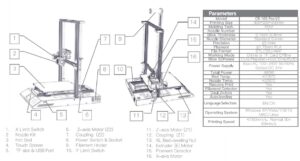
Introduction i9:”©f~*
11– – – 1 8
—————————————————————– ‘
1 Filament Holder~~&~~
1O Printing Platform jJEp:xp:;g
18 Filament Detector il/r~~;li!j
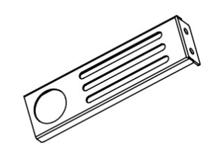
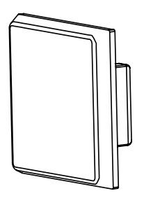
2 Control Box ~$!~
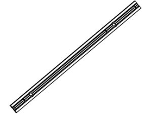
11 Pull Rod t.i’rlf
19 XE Transfer interface XE~Ji:l
3 LCD Screen fil.;f,lff
12 Base Frame ;j<Jl,~JEE~
20 X-axis Motor Xtib~i’/1,
4 Knob 11/fW.
13 Coupling ~
21 Z Limit Switch Z~llHi’L:ff:;1,c
5 USB per USB:li
14 Z-axis Motor(Z2) Z~~i’/l,(Z2)
22 Z-axisMotor(Zl) z~~i’/1,(Zl)
6 Storage Card Slot 1’¥~–lcl!i
15 Y Limit Switch Y~ll&1.i’r:ff:;1c
23 YZ Transfer interfac
YZ~Ji:l
7 Voltage Selection ~ffiJ!Ji’i~ 8 x Limit Switch X~~1.i’r:ff:;1c
16 Titan Extrusion Device~±§!!J’Hl:li’/1, 17 Y-axis Motor Ytib~m
24 Platform Connection i?.Pl<M!
25 Power Cable Connection ~;Jjiiffl.§l’,:f:;1,c
9 Nozzle Kit Pil!~ii’1~
‘-
2
¥*~~ Basic Parameters
Model I~”5
CR-10V3
Printing Size I .Bx~R’J
300*300*400mm
Molding Tech I .Bx~~* Nozzle Number I Pilt:~U;z~ Slice Thickness ItJJhfzi~ Nozzle Diameter I PjlP//HlH
FDM 1
0.lmm-0.4mm
Standard 0.4mm I~3.iil!c0.4mm
Precision I HfP*ii~ Fliament I HEPM11File Format ItJJh3Z’F-Ht:it Working Mode I HfPjj”:i:I’.; Slice Software I i:iJ*~tJJh~1!:!= Power Supply I Wt~’.~ffi Total Power I Wl~J:jJ$ Bed Temp I11.*~~5~~ Nozzle Temp I PjlPt/J~~5~~ Resume Print I iffi~gin
±0.lmm 1.75mm PLA STL/OBJ/AMF
Online or TF card offline I l!HJ,~TF-tfilWl,
Creality Slicer/Cura/Repetier-Host/Simplify3D Input! $#ii.J:AC115/230V 50/60Hz Outputl$tiil:±:l:DC 24V
350W ~100°( ~250°(
Yes I 3Zt~
Filament Detector I lffi11-Ml;DJ!
Yes I 3Zt~
Daul Z-Axis I xJ(Z$[iJ Auto Leveing I Elii.i.J~.l:JL
Yes I 3Zt~ No I 7f3Zt~
language Selection I 9:r~t)]~
English I ‘t1X
Operating System I ~~®J:*1-‘F~gfE Windows XP/Vista//7/8/10 MAC/Linux
Printing Speed IHEP~~
~180mm/s,Normall:i:E*~ 30-60mm/s
3
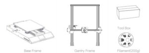
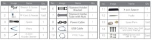
Parts List ~l’l~f!f:51~
I
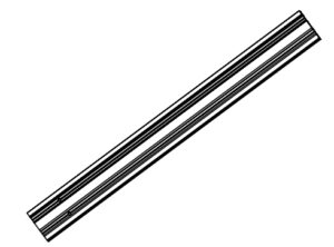
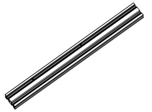
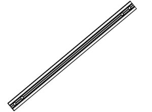
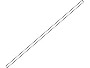
e Pull Rod I Hrff x 1
~
C, Filament I ~;M x 1
–lil
0 Gantry Frame I ftl’l~ x 1
B lllll___ll · l!!jj__________
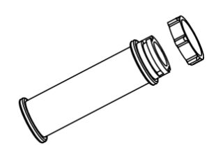
Spool & Nuts x 1
M~&:/,I~-jij
· Spool Holder x 1 M~
0 Base Frame I ~
x 1
8 Control Box I ~M
x 1
$ Tool list I~fil51~
M5X25 Bolt & Lock X 4
·
Washer
· M5X25 ffl~&sii!i!’mf”
Nozzle Cleaner x 1
—‘-· – – ~tt
:, >—C ·
(lti’._~ ~-
Cable Ties X 1 tL1i;
~:~;~;r Hex keys, Wrench x 1
(}
C, Tool Box I I~§ x 1
/ 7 — -“””-,,
(
‘
G) PTFE Tubing X 1
(spare part)
~m::lt~(ill-ilil
· Spade x 1
lfJJ
CY
El) Storage Card & X 1
Card Reader
l’¥fit-H
~-tf
~
G) M3xl8 Hexagon x4 Countersunk Head Screw
M3xl8i!sf.;J!l’JJJi::li<II~
~
G M5xl2 screws x 4 M5xl2llg/;
p
(P
· Diagonal Pliers x 1 ~m
& Material Detection x 1
I] ~~=::::o W Extension Cord
l#JiM~i!i!!!Jafil*!Ja
· L pull rod connector x 2 Ll!!11/i:fflllt14
~
.,. live bolts M6X35 X 4
W 5!Jtffl~M6X35
· MST nut x 4 M5Tl!J1ffljij
G, M6nut x4
M6ffljij
iwwD e
~ ~
-t!i) Po_wer Adapter x 1
Eg;J,l!Ji
· ScrewsM6X40 x 2
W’ t/*fflg/;M6X40
fli) Spare Limit switch x 1
ill-!llBIHi’Itf*
e
G M4T nut x 4 M4Tl!J1!1jij
G, Spare Parts x2
il!-llJPjPJo/lB14
~ b
~
limitswitchforZaxis x 1
W Z1l!illHi’Itf*
~
M4*16 cup head x 2
W’ screw
M4*161l!iltt:li<llH
~
LJ
G M5x30Hexagon Socket x 4 Button Head Screws M5x30[!s;’;;J!i’J’!”~:Ji<fflg!;
G M4x8 Hexagon Socket x 4 Button Head Screws M4x8i!s;’;;J!l’J’!”ll!il:li<II~
0 G Isolation Column x 4 ~il’itt
A Material Detection x 1 W Switch
l#Ji~~i!i!ltf*
4
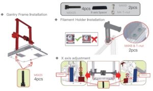
Install the Gantry Frame ~~1.El’l~
Q Gantry Frame I ftfl~ x 1
O Base Frame I litt~ x 1
A MSX25 Bolt & Lock Washer x 4 W MSX25 ~tt:&s!f!’iiHtl:/t 5
Twist the coupling to raise the X axis to the position as picture shown.
t’rQJl!Hill~fleX~m_tft¥1J~D~rfi5TT{li.il:o
Pull Rod Installation G
0 ·?!· ·
PullRod x4
; ,. til:ff
‘
. . ‘
~
/ I
L pull rod connector x 2
Lll!ltftffii~i’t
~
~
· live bolts M6X35 X 4 W J!~!lttM6X35
~ ~
ScrewsM6X40 x 2
· ;!Jl,*ll~M6X40
M5xl2 screws X 4
E) M5xl2!1~
(P
· MST nut X 4 MST!l!l!IJll
~ff) -· M6nut x 4 M6lll;t
M5x30Hexagon Socket X 4 1
Button Head Screws M5x30P;J:;’-;1/l’!”lffll3isll~
· Isolation Column x 4 flilll!itt
——— ….. ,
I
6
Install the Rack and Filament Detector
~ft
l’ffi~~fd!!
‘,
· Spool Holder X 1
~
Q– — –·
Material Detection Bracket x 1 lffi~~;!i!!;!;~
Material Detection Switch x 1 lffi~~li!!f f *
u
M4x8 Hexagon Socket x 4 Button Head Screws M4x8Pl1’;!(l’l’mll~dilll~
~
M4Tnut x 4
M4Tl!!i!lll;,
M3x18 Hexagon x 4
Countersunk Head Screw M3x18PlMl1i)Ekt!!~
7
,, _______________________ ,,
I, ,-_ —— — ___ …, ——, ‘ I
~l
111..a.-….LI
I
I
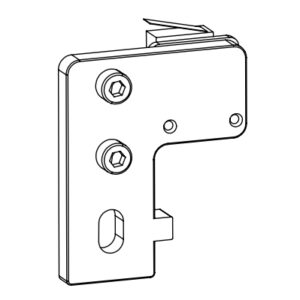
Xt
,
~AIn~HZgsoldttl~ahIe.lHlHulmHimi~t,,wixt;;JkXshHwwLf;iutthlc§t,hheffhfl2ooflj)er/MaZo4d*a1t6hx(eji’ogs~lo*c-kJ~:~~;tz!ol$!loithrtt~lhl~!etr1fl1tef1lf~tfFipc:1cXo!;if!iYleIDo!f~thJ1e:ogaot,y w;th two M4·16 cop head sccew.
~ W
limit switch for Z axis Zld!~i.Uff~
x 1
Ci) M4·15 cup head screw x 2 M4·1s~tt~li!ln
8
Cable Connection i~*H~Mz
Connect the modules to the Controller as illustrated and power on. J1ill!ijf-11Hllffl.J/i’li¥1J~ltLlH, HH<tl)Jli:
Connect the Stepper Motors according to the yellow labels on the 6pin (4-wire) side 11,’!&6pin (4;Jl) li .tli’1M/£mjf-J!;<, Connect the Limit Switches according to the yellow labels on the 3pin (2-wire) side J1iW.l3pin (2;Ji) l li .tli’fM,!mj-J~u:H*
Connect the aviation connectors to the ports with corresponding pins J/i’!U1@ttl’l9:a<JM”2’llf~
dJ
& Material Detection x 1 W Extension Cord
IIJi~~;romQ;*!Ji
1 ~®P · PowerAdapter x 1 W <tJli!Ji
i– ——-i
0
I
I
o
I
I
I
I
I I
Zl I I
!§i
~ 1_ – – – – – – – – … ——·
Caution
e Select the correct input voltage to match your local mains (115/230V)
e Damage can occur If voltage is set incorrectly.
e connect the power cord and turn the power switch to 1 to turn it on.
e Do not connect or disconnect the cables when the machine is powered on.
e llUcfiEfflla<Jltl.>–<llEiiJ~[!!;io/Sla’J:211:±t!!<tllm (115/230V)
· ~ li’1f9:-E,
mll!l~~.6J!m~.
e l!i’li’1llm~#~’1llmlH*~~,~~mHm.
e §m§~<tl~. ~~l!i’li~~Hl!i’li~.
,,— —- —————-,’
I
I
I
~
: – -, – – – – – – – :
0
,
Z2
I
1_ – – – – – – – –
,
I
I ,., ..·
I O .———, I
VI z ~—
9
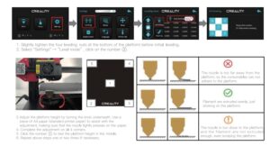
Bed Leveling iJal’fI’fii:l-
Prepare -Auto Home (Waiting for the nozzle to move to the left/front of the platform) -Prepare-Disable Steppers(Close stepper drive, release motor)
,itm-@J!Jli:,~ (~1~DPiD!il’~ivltUIJii’l’~ilu15) -,itm-*lltv~~l&ivl (ffb”)(~;jf],)
Info :::creen
~ ~ Pr I nt from TF
Ch-:1n;ie TF c =1rd
:t +
..
f1a,n
1
Mol,ie ax Is
+
– ~ – – – – – – – Set home offsets
..
D1s-:1ble stepper.;.
Info sct-een
~ ~
Pr In+. frc,m TF
Ch :in ~e TF c-:1rd
:t
..
fJa In Mol.Je ax Is
1
+
Auto home
+
Set h,:irne c,ff sets
D1.:-able steppers
f-Afif@_§_Wr_ ni _ _ _ _1·
~
L::1t191139e
-..
;il;-$.
·
..
..
ffi@. W.mi
~ ~
L::1t191J:1~e
;il;-$.
1 ..
-+
·
10
Move the nozzle the front/left leveling screw and adjust the platform height by turning the knob underneath (The thickness of a piece of A4 paper).
Use a piece of A4 paper (standard printer paper) to assist with the adjustment, making sure that the nozzle lightly scratches the paper. Complete the adjustment of the screw on all 4 corners.Repeat above steps 1-2 times if necessary.Keep adjusting until there is slight resistance on the A4 paper from the nozzle.
* ~iQJP]allJlj~~~..tJJllt-.tili:otl’iQJ~~, l}.Ji,tJ£P’J’~P]allJlj1l’.=~5li’TliilUHW,!;~;J;I;~, faJ~eJ<Jt,JO.lmm (-lAA4;E;a<J~J!t) o
~ff]j,JJ.;ffij,E!j-lJxM;MiU;/Jl}.J’J’>1l’.P]aPllilJUH~~t£A4;JUF~tUlao-(jx;;:’11,pJ/;11!l1’lt!R.i..tif,J’J’~~a<Jif,Ji,01′ f!Jil}.J~]jjilJ tt!:i’LiQJM;El;Bsl~~~~JIJ § PJallJlj a<J~11&:mtti0
,-
‘
, ————————————,
I
,, ____________________________________ , I
‘——————————————–‘
– -r!
· @
The nozzle is too far away from the platform, so the
-~ consumables can not adhere to the platform. £ OJID/liili’l’B;is;z, ;.~,c5’1a:r.l~tt’l’BLo
2=
2=
0
Filament are extruded evenly,just sticking on the platform.
;.tti/Hll!:,l’a, ~!Jzl’911tt’l’B Lo
2=
2=
CD
The nozzle is too close to the platform, and the filament are
not extruded enough, even scraping the platform.
OloJll/l(F!’B;!s;l!i,;.~mtll’flE,llEejW.:f’l’Bo
11
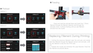
Preheating
r!M&
Method 1
I nf,:i screen
~ ~ Pr Int fr om TF Cf ,ang’:’ TF card
:t
..
Auto hoMe Set hc,rne c,ff:= et s
D 1.:-able :::tepFers
-t
Pt ehe3+_ Fl.A
-t
Pt ehe 3+_ ABS
+
Method 2
Info :::cre’:’n Prepare ~
~ Pr I t1+. from TF
:t
-t
..
Ha 1n
M~ -u–+-,-o-,-,-
t
FI l 3rnent
-t
-t
Store sett I t1~s
Control
t
B~ -~–d-:- – – – – – – – 0
..
Nozzle:
200
Fan .:,peed:
0
Preheat PLA conf
+
r[@.;al.rni
:i:*
~
L:1r,911d=”=’
~sjl.
..1
·
+
·
1[!:ll.;al.rni
i* l:i:m1J
….. .,…….
~sjl.
..1
· ·
…
·
..
0~11/!’::
200
12
When you wait for the temperature to rise, hang the filament over the Filament Holder.
31~W1~;Jll’i!Jt_trt-st ~nt,Hittl¥3t~_to
For smoother printing, the end of the filament should be placed as shown above. Y;J7Jll!ii~Ujt,ox:/JEP, ff;t;tB{)*yi/ii{n:ii@:PDl!l.olimo
i~ ·A
I
13
Load Filament “&*’1-
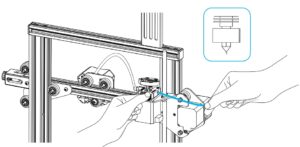
when the current temperature hits the target temperature, Pass the filament through the filament sensor, press the extrusion spring and feed in the filaments to the nozzle, and then keep await until you see the liquid filament comes out of the nozzle.
~mr;gJJ:JisiU 13 t~;.!i!.JJ:111, :mnM~i1Jlli~~;Dltl, ~ttmtilm~ii, :mnMtiliAffitilmJJ,JL~~lli!!DlfiL’li, ~fliUVmlil~!HmM5JiltilllP~ff-nMB ~ilt!liiG/Jxo
Tips: How to Replace the Filament? 1,Cutting filament near the Extruder and slowly feed new filament until they are fed into the new filament. 2, Withdrawing the filament quickly and feeding the new !aliment after nozzle preheated and filament pushed a little forward. Tips:Ji[JfoJ~jj!J,tW :t;;!-, ff:li!lffl1H:l:ltll~~~~;/Jgl!Ji, 11f:1Ji~tttlilll<J, Ei:llmttllllll<J-lllfl’il!t,J.Lt. :n1t=,fli11.IPllll’iFc, 1~~ttttiluJ’iJ1!-~Fc, ffil!Jl!it:l:l~tt, 1~ffi~ttzJo
I I I
14
Start Printing fHBHEP
Custom RepRap Information
RopRaomadries con bo,.s t ~ -or,, sohofa:,oo con ‘8t )Wl””‘1’ottrQ< ~ eue to re·e’Wthea,t,,jt cmilebefcre rt.ffir,Jton,curmchr,, If :,oolkii a <»f.Ut prc. . tor:,w,macrno addod thonrM<ei>1″‘-‘!!on ~
g~~:~s rw,_..,.1ne1, :,oo
O CR-=
Macm<l-“h X lrrm)
O cR-JO<O,l:R-30<0 O CR-400
0 CR-5ffiJ
O c·-:;cw _
M>cmii<loap(t, Y(mm ) Nozrle size (mm)
== I I CA-10V3
~
~
O CR-mm Q cR-l c.’O’-lOS
Q cR-lffi P!O
><oatodbod
Bed c ert<
i,0 , 0.O(RoS
t cd )
O cR-10&1
Q cR-lO S!5 O en
Oc=
Oc= –
O Erm-1 0 Erd9-,,.._-3 1
0 Er<laf-5
0 00..(E,:R~
·-
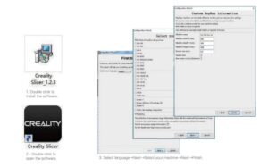
CrHlity Slicer_l.2.1msi
>>
( reality Slicer
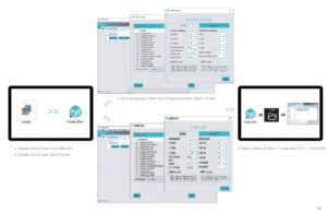
3. Select langue your machine
Next
Selct
Next
Finsh.
1. Double click to install the software. Ig.::j;!,~14 2, Double click to open the software. Ifflf~14
Hli t l . aoJtJ -H’Ullt,/il’l.l i i.!i. 4’oltJ iclc lll f’: B28′.Dl!i
l l if; fflTWf:t t l ‘ l l l i l l l : ~ : l l : # J t c·t::tw:
–
~
~ ~ M J.:i fMJffi a ! !
t~~
O cR-5 O CR-~ 0 CR-:mo
Q CR-DIO/CR-DIOS
O c·-<040 Oc·-=
“1Mftn, lll tJl!~
IH:lH9tl>il.b”Jiti
lli:liTIJ:A’!Mt;J,,,…, or~· l!il#
fliiM
=fr,i;-,oval
~
~
Q cR-9:BJ
li!lllilttf
~
Q CR-lOrti Q CR-10,’at-lOS O cR-1.WPto
U l ll!jljJ!,!t
I ll’&~<‘.· (0JJ)] I ___io i!fl i!IR<£itoj,;)
O CR-10 5<
0 CR-10S5
O c·-·
a,~
O c~ Pro
0 Erdef-l 0 Erdl,-, . -.:JP<o Q Erdar-5
o ,rn1turnt1u ·~
® Bii:!<:11.a
lf Z~ /ltW/1’11.1:&.-i
ilWfi’M·XsaJ!I( 11:ll:IIU:.lt!llitl l : 0
3.-f1!<;~Jl’Eig
Next ~fxst/i!
tJL~ Next Finsh,
i1;J;xiSt:il.
15
>>
,_
4.0pen the software :fl~J/;!ICtn}’-
Load
Selct
the file Wait
Load (~IIJDzf’i’) Jltmxf’I
–
for slicing to finish
Start Printing
:rHtnm
>>
5.Generate G-code, and save the geode file to storage card.
~PX G ft~ 1JiH
6.lnsert the storage card Print Select the file to be printed.
fE!j) fil”F
Jg;:’”filEW.
lz;:fE3~
~nEP:st14
1r 1t _ , r …. ,~r,
1
M-:11n
:t
-r ‘=’F ::at.=1,-ttt,-l
~
—
Ft-I -t -t t — fl Tf
–
. ·
· >>
,.
ORefresh
Rabb I t . 9c,Jde test .geode
ffi”@.Wjjjj
t
.3::;j!;!ajl.
f
;jf~
l’i’ffi!J
L-:1r1~1ia-1….
;j!;!ajl.
+
+ +
+
>>
l’JRefre:::h
~ ~
File names must be Latin letters or numbers, not Chinese
characters or other special symbols
J :st1H5 ~~t.JLT~~li!G~~. ;i;:,m~5:ll~li!G:let1-t!J~?!i<N”5
Notes: For details on the software instructions, please refer to the slicing software manual in the memory card!
;,l.!llt~~: ~14-fiefflJ.Jl.a.llWffl, i.!!ii!fl’fil”””Fpgt:JJF”~14-fieffl-¥Jlfr !
16
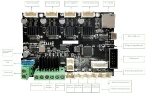
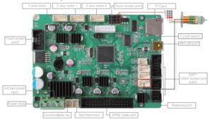
Circuit Wiring
~ H
X axis motor
X’lil~l/1
o[
t!l ~ti]
~il
~I
G: uEnJ~nG: EJ
!Cl .. 11:1 . .
E2 axis motor E2′,l~il
.. J[: -]
ti]
Iii
tIii!l9″··M~ t!Iiil
ti]
i
G: E]
E] [:]m E] 00
H~U IJ ~uua I ~nun
0
Power input
~;!ili!JA
17
Heating pipe1
1mmtt 1
Storage Card
8’11if-Nl’i
Micro USB Port Micro USB ti
EXP1/12864 Screen interface EXP1/12884 }}/:l!Wm
EXP2/12864 Screen interface EXP2/12864
m1;rna:1
Y Limit switch
Yi!limi!z
Z Limit switch
Z’lilmi!z
Reserved port liilOO!lH:l
Reserved port
m1mm
BL-Touch Reserved port BL-Touch jjiji1iJjl[Q
Trouble-shooting
End
TF card File name
1, Erase t he TF card 2, Format the TF card 3, Replace the TF card
1. Rename the file wi th alphabet and numbers
Sl i ce
1. Move the model and rcst.’.lrt the slicing
> – – – – – 2, Restore the model with software
limit sw i tch
1. Reconnect the cables 2, Check via the replacement method
1. Reconnect the cables 2, Check vi a the replacement method
hot bed
1. Reconnect the cables
Thermistor
1. Reconnect the cables
Heat pipe
L Reconnect the cables
Thermistor
Slice/ T im i n g belt
Coupl ing
1. Reconnect the cables
1, Restart the slicing 2, Adjust the tension of the synchronous
belt
I, Fasten the coupling
Other Filament E stepper
I , Cl ean t he f i lament 2, Replace f i lament
l, Reconnect the cables 2, Check via. the replacement method
Resolved daused l contact for roplacnent The fault cannot be identified, r:ont1u:t to reso lved
18
1, jfJ;l!UJlt 2. lilitftUJlt 3. if~UJlt
1. ~iJJ!llllili:l!IJHU/rtJJit 2. ill!l!l!J!i:~f’f!J!i:!lll!
~-1:
~-_ 1:~ 8:fl :t-~ :- :-:-:-:-~
~ b · ·—-~-~-=-:-7:-:
~
~
~
<B>ll’c i”l
~ -~: , ~:.
1. lii!’1!lll 1. lii!’1!lll
~—–,
IJJftlf”l$’ill
t
–
–
–
–
~ _
_
_ 2_.
1.liffilJJ;t _iJ_.!l!,_! f_o”l _,$_’ill_l’·_’!_ i
_
_ ~
1. i'<liUt~.1<iili!l.liE 2. if~fl:~
E’1!!Ji.
, . lli:i!’1!lll 2. /!lM~i~!!H!’
19
Due to the differences between different machine models, the physical objects and the final images can differ.The final explanation rights shall be reserved by Shenzhen Creality 3D Technology Co., Ltd. ~4ij~t/lll!!=f151,:ll;!lm-‘alfiliiJ/JglJJili~J”F, illl>:ll;!lm;is)l, Ji,~ffillm:J;*tjll”$frl1fl=§!l’fl!ill!l.0a’J/ilill o
SHENZHEN CREALITY 3D TECHNOLOGY CO.,LTD. 11 F & Room 1201,Block 3,JinChengYuan,Tongsheng Community,
Dalang,Longhua District,Shenzhen,China,518109 Oflicial Website: www.creality.com Tel: +86 755-8523 4565 E-mail: [email protected] [email protected]
0’a’Jl»lil~: www.cxsw3d.com ~~%-J:MJl: 400 6133 882
0755-8523 4565