behringer Ultra-DI DI600P
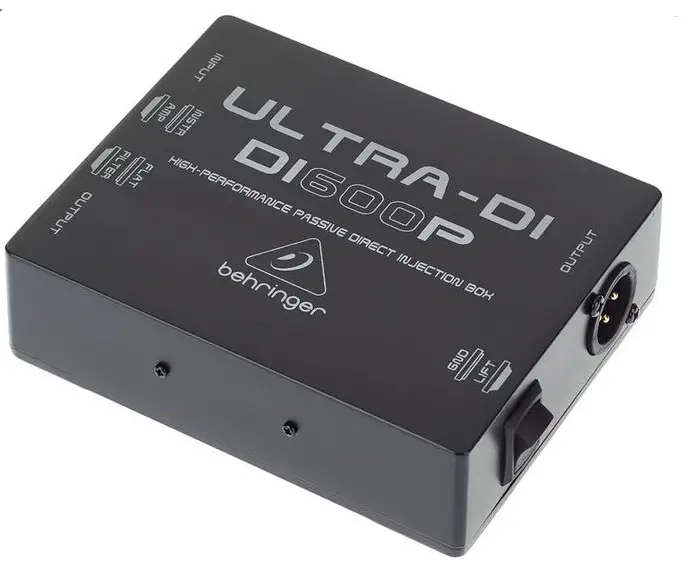
Thank you for showing confidence in Behringer products by purchasing the ULTRA-DI DI600P. The DI600P is a high-performance passive direct injection box.
Please read the safety instructions that appear at the end of this document.
Being on stage or in the studio, musicians often look for ways to connect certain signal sources directly to the mixing console. Even though this approach has obvious advantages, there are still some technical hurdles obstructing its implementation. For example, keyboards seldom feature balanced outputs, and guitars can not be directly connected to mixing consoles because of the high impedance of guitar signals.
The DI600P lets you directly tap into a high-impedance, unbalanced signal—for example, the signal between a guitar and a guitar amp. From there on, you can feed the signal directly to a mixing console.
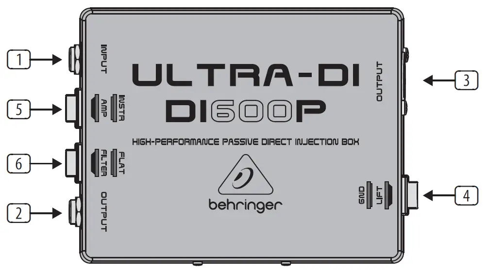
Control Elements

- Use the INPUT (¼” TS) connector for connecting signal sources.
- OUTPUT (¼” TS). This is the unbalanced parallel output. Connect it to the input of your backline or monitor amplifier.
Because the connectors (1) and (2) are wired in parallel, the OUTPUT connector can be used both as an input and as a direct unbalanced output of the INPUT signal. For the latter, you can for example connect OUTPUT with the input of a monitor amplifier. - OUTPUT (XLR): This is the balanced mic-level output. Use a high-quality balanced microphone cable to establish connection.
- Using the GND LIFT (ground lift) switch, you can fully separate input and output grounding. Depending on how the equipment to which your DI600P is connected is grounded, using the GND LIFT switch lets you lower hum noise or ground loops. When the GND LIFT switch is in LIFT position, the ground connection is interrupted.
- The INST/AMP attenuation switch (30 dB) increases the operating range of the DI600P considerably, from low signal levels of a high-impedance mic or a guitar (INST), all the way to speaker connectors of a guitar amplifier (AMP).
- Switchable FILTER for guitar applications (7.5 kHz, -3 dB).
The SERIAL NUMBER of the DI600P is located at the bottom.
Applications
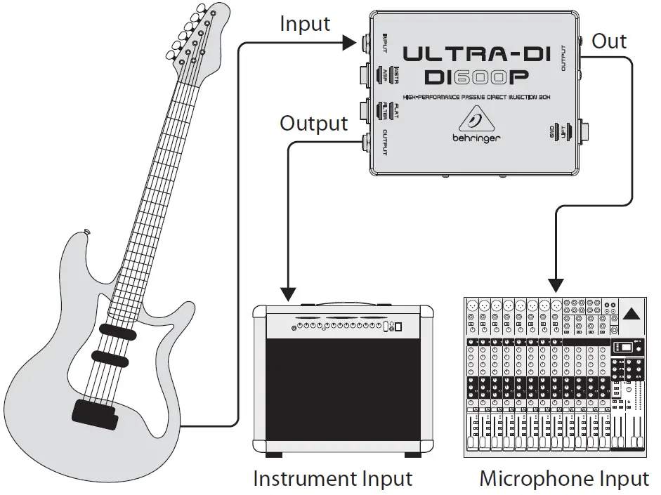
Connecting an instrument signal
This illustration shows the standard application of a DI-box. The signal feeding the amplifier remains unchanged; it is simply taken and routed into the amp. The low-impedance balanced signal is forwarded to the mic input of the mixing console. This application has its advantages particularly with bass guitars, because very few microphones can linearly transmit bass frequencies with high signal levels. If you are using effects, insert the DI600P after the effects device, so that you can monitor the effects via the PA system or the recording as well.
Taking a signal from a speaker output
Sometimes, you want to take a signal directly from a speaker output, even though just one speaker output is available. When you set the INST/AMP switch to AMP, you can connect an amp output to your mixing console (up to 3,000 Watts into 4 Ohms), without worrying that it will be damaged due to overload.
If you are using a tube amp, you must connect a speaker or a similar load resistance to the parallel ¼” TS output.
Before connecting to a loudspeaker connector, please make sure that the GROUND LIFT switch is in LIFT position (no ground connection). This prevents accidental shorting of the amp output. Besides, the tip of the input connector should be connected to the speaker connector marked with red. The metal casing of the DI600P should in no case have physical contact to other equipment.
Specifications
Frequency response 40 Hz (-3 dB) to 20 kHz
THD+N (Distortion) 0.003% @ 1 kHz, input level +4 dBu
Input ¼” TS (unbalanced)
Level change (input → output) -20 dB
Output Balanced XLR
Impedance ratio (input → output) 110 : 1
INST/AMP switch 30 dB pad
Filter switch Low pass @ 7.5 kHz (-3 dB)
Dimensions (H x W x D) 1.4 x 3.75 x 5″ (35 x 95 x 128 mm)
Weight approx. 0.66 lbs (0.3 kg)
Behringer continuously strives to assure the highest quality standards possible.
Required modifications may be implemented without prior notice. Technical data and the appearance of the unit may deviate from the above values and/or illustrations.
Warranty
For the applicable warranty terms and conditions and additional information regarding Music Tribe’s Limited Warranty, please see complete details online at musictribe.com/warranty.
Important Safety Instructions
- Read these instructions.
- Keep these instructions.
- Heed all warnings.
- Follow all instructions.
- Do not use this apparatus near water.
- Clean only with dry cloth.
- Install in accordance with the manufacturer’s instructions.
- Only use attachments/accessories specified by the manufacturer.
- Refer all servicing to qualified service personnel.
Servicing is required when the apparatus has been damaged in any way.
Music Tribe accepts no liability for any loss which may be suffered by any person who relies either wholly or in part upon any description, photograph, or statement contained herein. Technical specifications, appearances and other information are subject to change without notice. All trademarks are the property of their respective owners. Midas, Klark Teknik, Lab Gruppen, Lake, Tannoy, Turbosound, TC Electronic, TC Helicon, Behringer,
Bugera, Auratone and Coolaudio are trademarks or registered trademarks of Music Tribe Global Brands Ltd. © Music Tribe Global Brands Ltd. 2019 All rights reserved.
Zhongshan Eurotec Electronics Limited
No. 10 Wanmei Road, South China Modern Chinese Medicine Park, Nanlang Town, 528451, Zhongshan City, Guangdong Province, China
![]()
Guitar Amp Modeler/Direct Recording Preamp/DI Box
Thank you for showing your confidence in us by purchasing the V-TONE GUITAR GDI21. This high-quality guitar modeling driver is designed for hands-on musicians and no-frills types. We have rebuilt different circuitries and components from famous amps, and packed them into one housing. You can alternate between several different amp re-creations, gain settings and mic placements with a flick of a switch–intuitively and with minimal effort. In addition, the GDI21 functions as standard ultra-transparent direct injection box when used in bypass mode.
A DI (Direct Injection) box allows you to send a signal directly from an unbalanced, high-impedance output (like an electric guitar) and connect it directly to the balanced mic input of a mixing console.
Whether for stage, recording, rehearsal or warm-up, BEHRINGER’s V-TONE GUITAR GDI21 is a natural choice for all players who want an arsenal of different tones.
Control Elements
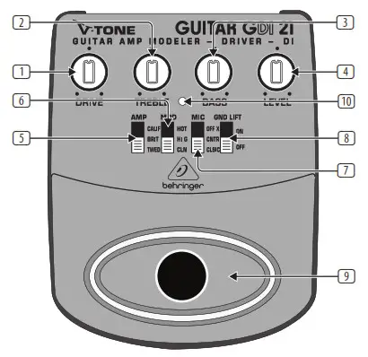
Control elements
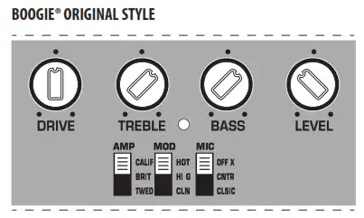
- The DRIVE control adjusts the overall amount of gain and overdrive, similar to pushing the output section of a tube amp.
- The TREBLE control governs the high-frequency range of the signal (±12 dB).
- The BASS control allows you to boost/cut the low-frequency range (±12 dB).
- The LEVEL control adjusts the output level of the GDI21.
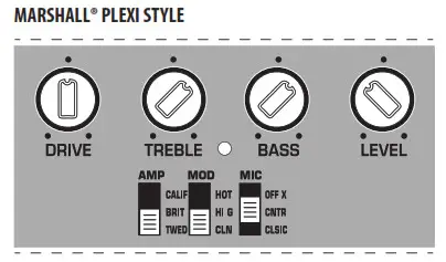
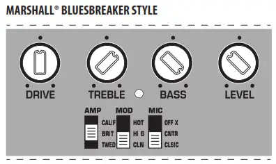
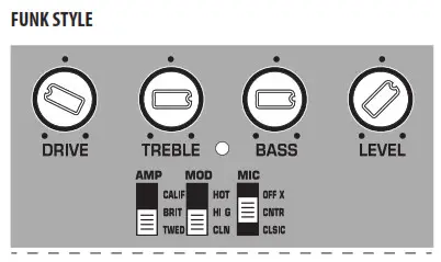
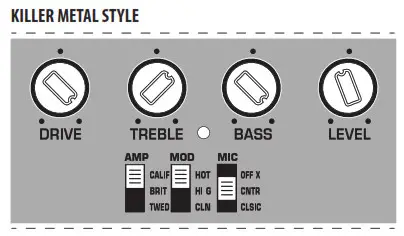
- Use the AMP switch to select one of three great classic tube amps. You will recognize these classic amp tones as soon as you hear them. For crystal-clear, transparent sounds with dynamic bass select TWE(E)D. For aggressive mids and incredible sustain select BRIT(ISH). Rounder and more evened-out (yet still sophisticated) sounds can be dialed up if you select CALIF(ORNIAN); it’s perfect for leads.
- Use the MODE switch to dial up one of three gain settings (HOT, HI G(AIN), CL(EA)N) that you want to combine with the amp setting.
- The MIC switch simulates the microphone placement (orientation and distance) in relation to the cabinet. Select CL(AS)SIC (distant mic placement without ambience) to achieve high mid-range content and a greater definition of notes like with classic early tube amps. In C(E)NT(E)R (close miking at the center of a cone) you get greater high mid-range content and increased low-end for mega crunchy results. OFF (A)X(IS) (close miking at the edge of a cone) is very similar to CENTER, but produces a smoother, softer sound with less upper mid-range content; perfect in combination with MODE position HOT.
- When activated, the GND LIFT disconnects the ground connection between input and output. Depending on the grounding of the connected equipment, this can eliminate hum or ground loops.
- Use the footswitch to activate/deactivate all the tone functions (EQ, DRIVE, modeling). When deactivated, the GDI21 functions solely as a standard transparent DI box.
- This LED illuminates when the effect is activated (see 8).
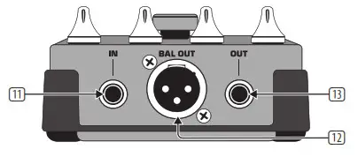
- Use this ¼” TS INPUT connector to plug in the instrument cable of your guitar or other instruments.
- BAL OUT is the GDI21’s balanced mic level output. Use a high-quality, balanced XLR (microphone) cable to connect the driver to a mixing console.
- The unbalanced ¼” TS OUT connector sends the signal to your guitar amp.

- SERIAL NUMBER. The serial number of the GDI21 is located at the bottom.
- BATTERY COMPARTMENT. Open the lid to install or replace the 9 V battery.
 The GDI21 is powered as soon you insert a plug into the INPUT. The battery is “disconnected” when the plug is removed. For this reason, the GDI21 has no on/off switch. To prolong battery life, always disconnect the input when the driver is not in use.

Power supply connector - Use the DC IN connection to plug in a 9 V power supply (not included).
Safety Instructions
Do not use near water, or install near heat sources. Use only authorized attachments/accessories. Do not service product yourself. Contact our qualified servicing personnel for servicing or repairs, especially when power supply cord or plug is damaged.
Warranty
Please register your new BEHRINGER equipment right after your purchase by visiting http://behringer.com and read the terms and conditions of our warranty carefully.
Specifications
| Input | |
| Connector | ¼” TS |
| Impedance | 1 MΩ |
| Output | |
| Connector | ¼” TS |
| Impedance | 1 kΩ |
| Balanced Output | |
| Connector Impedance | XLR |
| Power supply | 200 Ω |
| Power connector | 9 V, >50 mA DC regulated |
| Battery | 2 mm DC jack, negative center |
| Power consumption | 9 V type 6LR61 |
| Connector Impedance | 25 mA |
| Dimensions/Weight | |
| Dimensions (H x W x D) | approx. 5 x 3 9/10 x 2″
approx. 127 x 100 x 50 mm |
| Weight | approx. 1.01 lbs / 0.46 kg |
Sample Settings

 MUSIC Tribe accepts no liability for any loss which may be suffered by any person who relies either wholly or in part upon any description, photograph, or statement contained herein. Technical specifications, appearances and other information are subject to change without notice. All trademarks are the property of their respective owners. MIDAS, KLARK TEKNIK, LAB GRUPPEN, LAKE, TANNOY, TURBOSOUND, TC ELECTRONIC, TC HELICON, BEHRINGER, BUGERA and COOLAUDIO are trademarks or registered trademarks of MUSIC Tribe Global Brands Ltd. © MUSIC Tribe Global Brands Ltd. 2018 All rights reserved.
![]()
EUROPORT EPS500MP3
Ultra-Compact 500-Watt 8-Channel Portable PA System with MP3 Player,
Reverb and Wireless Option
![]()
Important Safety Instructions

 Terminals marked with this symbol carry an electrical current of sufficient magnitude to constitute a risk of electric shock. Use only high-quality professional speaker cables with ¼” TS or twist-locking plugs pre-installed. All other installation or modifications should be performed only by qualified personnel.
This symbol, wherever it appears, alerts you to the presence of uninsulated dangerous voltage inside the enclosure – voltage that may be sufficient to constitute a risk of shock.
This symbol, wherever it appears, alerts you to important operating and maintenance instructions in the accompanying literature. Please read the manual.
Caution
To reduce the risk of electric shock, do not remove the top cover (or the rear section). No user-serviceable parts inside. Refer servicing to qualified personnel.
Caution
To reduce the risk of fire or electric shock, do not expose this appliance to rain and moisture. The apparatus shall not be exposed to dripping or splashing liquids and no objects filled with liquids, such as vases, shall be placed on the apparatus.
Caution
These service instructions are for use by qualified service personnel only. To reduce the risk of electric shock do not perform any servicing other than that contained in the operation instructions. Repairs have to be performed by qualified service personnel.
- Read these instructions.
- Keep these instructions.
- Heed all warnings.
- Follow all instructions.
- Do not use this apparatus near water.
- Clean only with a dry cloth.
- Do not block any ventilation openings. Install in accordance with the manufacturer’s instructions.
- Do not install near any heat sources such as radiators, heat registers, stoves, or other apparatus (including amplifiers) that produce heat.
- Do not defeat the safety purpose of the polarized or grounding-type plug. A polarized plug has two blades with one wider than the other. A grounding-type plug has two blades and a third grounding prong. The wide blade or the third prong is provided for your safety. If the provided plug does not fit into your outlet, consult an electrician for the replacement of the obsolete outlet.
- Protect the power cord from being walked on or pinched particularly at plugs, convenience receptacles, and the point where they exit from the apparatus.
- Use only attachments/accessories specified by the manufacturer.
- Use only with the cart, stand, tripod, bracket table specified by the manufacturer, or sold with the apparatus. When a car is used, use caution when moving the cart/apparatus combination to avoid injury from tip-over.
- Unplug this apparatus during lightning storms or when unused for long periods of time.
- Refer all servicing to qualified service personnel. Servicing is required when the apparatus has been damaged in any way, such as power supply cord or plug is damaged, liquid has been spilled or objects have fallen into the apparatus, the apparatus has been exposed to rain or moisture, does not operate normally, or has been dropped.
- The apparatus shall be connected to a MAINS socket outlet with a protective earthing connection.
- Where the MAINS plug or an appliance coupler is used as the disconnect device, the disconnect device shall remain readily operable.
- Correct disposal of this product: This symbol indicates that this product must not be disposed of with household waste, according to the WEEE Directive (2012/19/EU) and your national law. This product should be taken to a collection center licensed for the recycling of waste electrical and electronic equipment (EEE). The mishandling of this type of waste could
 have a possible
 - negative impact on the environment and human health due to potentially hazardous substances that are generally associated with EEE. At the same time, your cooperation in the correct disposal of this product will contribute to the efficient use of natural resources. For more information about where you can take your waste equipment for recycling, please contact your local city office or your household waste collection service.
- Do not install in a confined space, such as a bookcase or similar unit.
- Do not place naked flame sources, such as lighted candles, on the apparatus.
- Please keep the environmental aspects of battery disposal in mind. Batteries must be disposed of at a battery collection point.
- This apparatus may be used in tropical and moderate climates up to 45°C.
LEGAL DISCLAIMER
Music Tribe accepts no liability for any loss which may be suffered by any person who relies either wholly on or in part upon any description, photograph, or statement contained herein. Technical specifications, appearances, and other information are subject to change without notice. All trademarks are the property of their respective owners. Midas, Klark Teknik, Lab Gruppen, Lake, Tannoy, Turbosound, TC Electronic, TC Helicon, Behringer, Bugera, Oberheim, Auratone, and Coolaudio are trademarks or registered trademarks of Music Tribe Global Brands Ltd. © Music Tribe Global Brands Ltd. 2021 All rights reserved.
LIMITED WARRANTY
For the applicable warranty terms and conditions and additional information regarding Music Tribe’s Limited Warranty, please see complete details online at musictribe.com/warranty.
EUROPORT EPS500MP3 Hook-up
Step 1: Hook-Up

EUROPORT EPS500MP3 Controls
Step 2: Controls
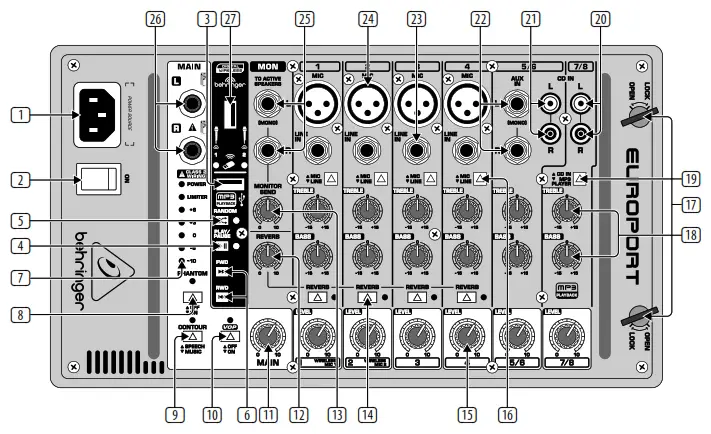
| 1 | POWER SOURCE – Connect the included IEC cable to this socket and into a mains outlet. |
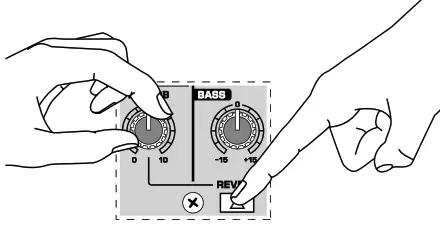
18 | TREBLE/BASS EQ knobs adjust hi and low frequencies by ±15 dB (same for channels 1-8). |
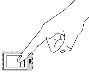
| 2 | POWER ON switch turns the power to the unit on and off. |
19 | CD IN/MP3 PLAYER button switches between a stereo signal connected to stereo channel 7/8 and the onboard MP3 player. |
| 3 | USB drive input jack for connecting an external USB memory device. |
20 | CD IN L and R stereo inputs for connecting an external stereo source via RCA cables. |
| 4 | MP3 PLAY/PAUSE button | 21 | Same as inputs on channel 7/8. |
| 5 | MP3 PLAYER RANDOM button shuffles playback of files from USB drive. |
22 | AUX IN jacks for connecting ¼” mono or stereo sends from a single sound source. |
| 6 | ( FWD and RWD buttons for skipping to the next or previous file. |
23 | LINE IN jack connects instruments, sub-mixers, or other line-level sources (balanced or unbalanced) using cables with ¼” plugs. |
| 7 | LIMITER LED and VU METER display the signal level and when the LIMITER reduces the signal in the event of a surge. |
24 | MIC input jack for dynamic or condenser microphones connected with XLR cables. |
| 8 | PHANTOM power button engages 48 V power for condenser microphones. |
25 | MON(ITOR) OUT jacks for routing stereo signal to external powered speakers. |
| 9 | CONTOUR button changes the frequency boost to optimize for speech or music. |
26 | MAIN OUT(PUT) jacks for connecting the power amp to speakers using speaker cables with ¼” plugs. |
| 10 | VOP button dims the stereo channels when there is signal activity on channels 1-4. |
27 | WIRELESS mic dongle jack for use with optional wireless microphones. |
| 11 | MAIN volume knob controls the overall volume to the MAIN outputs. |
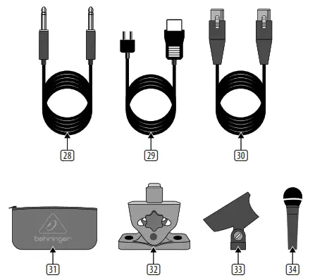
28 | Speaker Cables (6100 mm x 2) |
| 12 | REVERB knob adjusts the amount of reverb applied to channels 1-4. |
29 | Power Cable |
| 13 | MONITOR SEND knob adjusts the volume of the signal routed out the MON left and right jacks. |
30 | Mic Cable (6100 mm) |
| 14 | REVERB button activates the reverb effect on channels 1-4 individually. |
31 | Mic Bag |
| 15 | LEVEL knob adjusts the channel volume (same for channels 1-8). |
32 | Mic Stand Adapter Bracket |
| 16 | MIC/LINE button switches between line level input and balanced XLR input. |
33 | Mic Clip |
| 17 | OPEN/LOCK latches for attaching/detaching the powered mixer from the speaker. |
34 | XM1800S Microphone |
EUROPORT EPS500MP3 Getting started
- Remove the powered mixer and accessories from the storage compartments on the rear of the speakers. The supplied accessories include: 2 speaker cables (5 m), power cable, microphone cable, 1 XM1800S microphone, mic clip, mic bag, and mixer mic stand adapter bracket.
- With the power turned off connect the included speaker cables to the inputs on the speakers and to the MAIN OUT jacks on the powered mixer.
- Connect the included XM1800S microphone via the included mic cable to an XLR input on the powered mixer.
- Connect all other microphones, line levels, and stereo sources to the powered mixer. (FR)
- Set your channel LEVEL knobs to the 9 o’clock position and the MAIN volume knob to “0”.

- Power up all external devices.
- Power up the unit by pressing the POWER ON switch.

- Slowly turn the MAIN knob up 1/3 of the way.
- Control the relative levels of microphones and input sources by adjusting each channel’s Level knob.

- Add reverb to channels 1-4 by pressing the channel’s REVERB button and adjusting the REVERB knob.
- Press the CONTOUR button to choose between SPEECH and MUSIC modes.
- Press the VOP button to activate/ deactivate the voice-over priority feature. When activated, the VOP function dims the stereo channel volumes when microphone input is detected on channels 1-4.
- Make final adjustments to the output sound using the MAIN knob. If the VU meter shows the output signal at +6 with the LIMITER LED lighting up repeatedly, reduce the output by turning the MAIN knob to the left.

MP3 PLAYER, Reproductor MP3, Lecteur MP3, MP3 Player, MP3 Player
- Insert USB flash drive with MP3 content into the MP3 PLAYER USB jack.

- Push the CD IN/MP3 PLAYER button on channel 7/8 to select the MP3 PLAYER function.

- Press the PLAY/PAUSE button to start or stop the playback of MP3 files on the USB drive.
- Press the FWD or RWD buttons to skip to the next or the previous file.
- Press the RANDOM button to have the MP3 files play in random order (LED will light up when this feature is engaged).
- Adjust the volume level and EQ settings using the knobs on channel 7/8.
Specifications
| Amplifier | |
| Max output power (Peak power) | 250 W + 250 W |
| Limiter | Optical |
| Microphone Inputs | |
| Type | XLR, balanced |
| Sensitivity | -54 dBV |
| Impedance | 2.2 kΩ |
| Line Inputs | |
| Type | ¼” TRS connector, balanced |
| Sensitivity | -11 dBV |
| Impedance | 10 kΩ |
| Stereo Line Input (5/6) | |
| Type | ¼” TRS connector, balanced |
| Sensitivity | -11 dBV |
| Impedance | 10 kΩ |
| RCA Input (5/6) | |
| Sensitivity | -11 dBV |
| Impedance | 10 kΩ |
| RCA Input (7/8) | |
| Sensitivity | -11 dBV |
| Impedance | 15 kΩ |
| MP3 Playback: USB Type A | |
| File system | FAT 16, FAT 32 |
| Format | MP3 |
| Bit rates | 8 – 320 kbps, VBR |
| Sample rates | 8 kHz, 16 kHz, 32 kHz, 11.025 kHz, 22.05 kHz, 44.1 kHz, 12 kHz, 24 kHz, 48 kHz |
| Wireless System | |
| Connector | USB 3.0 |
| Frequency band | 2.417 ~ 2.471 GHz |
| Frequency response (Wireless Link) | 20 Hz – 14.7 kHz +0/-0.3 dB |
| Range | Max. 120 m (line of sight) |
| Audio Outputs | |
| Type | ¼” TS, unbalanced |
| Impedance | 1 kΩ |
| Level Control | |
| Input trim | -∞ to +16.5 dB |
| Max. input level | 26 dBu |
| Loudspeaker System Data | |
| Woofer | 8″ / 209 mm |
| Tweeter | 1″ / 25.4 mm |
| Frequency response (-10 dB) | 50 Hz to 20 kHz |
| Crossover frequency | 2.5 kHz |
| Equalizer | |
| High | ±15 dB @ 10 kHz |
| Low | ±15 dB @ 80 Hz |
| Microphone | |
| Type | Behringer XM1800S, Dynamic |
| Frequency response | 80 Hz – 15 kHz |
| Power Supply | |
| Voltage (Fuses) | |
| USA / Canada | 100 -120 V~, 50/60 Hz |
| UK / Australia | 220 – 240 V~, 50/60 Hz |
| Europe | 220 – 240 V~, 50/60 Hz |
| China / Korea | 220 – 240 V~, 50/60 Hz |
| Japan | 100 -120 V~, 50/60 Hz |
| Power consumption | Max. 90 W |
| Mains connection | Standard IEC receptacle |
| Dimensions/Weight | |
| H x W x D | Appr. 18.3 x 10.87 x 10.1″ Appr. 466 x 276 x 257 mm |
| Weight | Appr. 41.3 lbs / 18.8 kg |
Other important information
1. Register online.
Please register your new Music Tribe equipment right after you purchase it by visiting musictribe.com. Registering your purchase using our simple online form helps us to process your repair claims more quickly and efficiently. Also, read the terms and conditions of our warranty, if applicable.
2. Malfunction.
Should your Music Tribe Authorized Reseller not be located in your vicinity, you may contact the Music Tribe Authorized Fulfiller for your country listed under “Support” at musictribe.com. Should your country not be listed, please check if your problem can be dealt with by our “Online Support” which may also be found under “Support” at musictribe.com. Alternatively, please submit an online warranty claim at musictribe.com BEFORE returning the product.
3. Power Connections.
Before plugging the unit into a power socket, please make sure you are using the correct mains voltage for your particular model. Faulty fuses must be replaced with fuses of the same type and rating without exception.
FEDERAL COMMUNICATIONS COMMISSION COMPLIANCE INFORMATION
Behringer
EUROPORT EPS500MP3
Responsible Party Name: Music Tribe Commercial NV Inc.
Address: 5270 Procyon Street, Las Vegas NV 89118, United States
Phone Number: +1 702 800 8290
EUROPORT EPS500MP3
This equipment has been tested and found to comply with the limits for a Class B digital device, pursuant to part 15 of the FCC Rules. These limits are designed to provide reasonable protection against harmful interference in a residential installation. This equipment generates, uses, and can radiate radio frequency energy and, if not installed and used in accordance with the instructions, may cause harmful interference to radio communications. However, there is no guarantee that interference will not occur in a particular installation. If this equipment does cause harmful interference to radio or television reception, which can be determined by turning the equipment off and on, the user is encouraged to try to correct the interference by one or more of the following measures:
- Reorient or relocate the receiving antenna.
- Increase the separation between the equipment and receiver.
- Connect the equipment into an outlet on a circuit different from that to which the receiver is connected.
- Consult the dealer or an experienced radio/TV technician for help. This device complies with Part 15 of the FCC rules.
Operation is subject to the following two conditions: (1) this device may not cause harmful interference, and (2) this device must accept any interference received, including interference that may cause undesired operation. Important information:
Changes or modifications to the equipment not expressly approved by Music Tribe can void the user’s authority to use the equipment.
![]()
Hereby, Music Tribe declares that this product is in compliance with Directive 2014/35/EU, Directive 2014/30/EU, Directive 2011/65/EU and Amendment 2015/863/EU, Directive 2012/19/EU, Regulation 519/2012 REACH SVHC and Directive 1907/2006/EC.
Full text of EU DoC is available at https://community.musictribe.com/
EU Representative: Music Tribe Brands DK A/S
Address: Ib Spang Olsens Gade 17, DK – 8200 Aarhus N, Denmark
![]()
FEEDBACK DESTROYER FBQ1000
Automatic and Ultra-Fast Feedback Destroyer/Parametric EQ with 24 FBQ Filters
![]()
Important Safety Instructions
 Terminals marked with this symbol carry an electrical current of sufficient magnitude to constitute a risk of electric shock. Use only high-quality professional speaker cables with ¼” TS or twist-locking plugs pre-installed. All other installation or modifications should be performed only by qualified personnel.
This symbol, wherever it appears, alerts you to the presence of uninsulated dangerous voltage inside the enclosure – voltage that may be sufficient to constitute a risk of shock.
This symbol, wherever it appears, alerts you to important operating and maintenance instructions in the accompanying literature. Please read the manual. Caution To reduce the risk of electric shock, do not remove the top cover (or the rear section). No user-serviceable parts inside. Refer servicing to qualified personnel.
 Caution
To reduce the risk of fire or electric shock, do not expose this appliance to rain and moisture. The apparatus shall not be exposed to dripping or splashing liquids and no objects filled with liquids, such as vases, shall be placed on the apparatus.
Caution
These service instructions are for use by qualified service personnel only. To reduce the risk of electric shock do not perform any servicing other than that contained in the operation instructions. Repairs have to be performed by qualified service personnel.
- Read these instructions.
- Keep these instructions.
- Heed all warnings.
- Follow all instructions.
- Do not use this apparatus near water.
- Clean only with dry cloth.
- Do not block any ventilation openings. Install in accordance with the manufacturer’s instructions.
- Do not install near any heat sources such as radiators, heat registers, stoves, or other apparatus (including amplifiers) that produce heat.
- Do not defeat the safety purpose of the polarized or grounding-type plug. A polarized plug has two blades with one wider than the other. A grounding-type plug has two blades and a third grounding prong. The wide blade or the third prong are provided for your safety. If provided plug does not fit into your outlet, consult an electrician for replacement of the obsolete outlet.
- Protect the power cord from being walked on or pinched particularly at plugs, convenience receptacles, and the point where they exit from the apparatus.
- Use only attachments/accessories specified by the manufacturer.
- Use only with the cart, stand, tripod, bracket or table specified by the manufacturer, or sold with the apparatus. When a car is used, use caution when moving the cart/apparatus combination to avoid injury from tip-over.

- Unplug this apparatus during lightning storms or when unused for long periods of time.
- Refer all servicing to qualified service personnel. Servicing is required when the apparatus has been damaged in any way, such as power supply cord or plugis damaged, liquid has been spilled or objects have fallen into the apparatus, the apparatus has been exposed to rain or moisture, does not operate normally, or has been dropped.
- The apparatus shall be connected to a MAINS socket outlet with a protective earthing connection.
- Where the MAINS plug or an appliance coupler is used as the disconnect device, the disconnect device shall remain readily operable.
- Correct disposal of this product: This symbol indicates that this product must not be disposed of with household waste, according to the WEEE Directive (2012/19/EU) and your national law. This product should be taken to a collection center licensed for the recycling of waste electrical and electronic equipment (EEE). The mishandling of this type of waste could have a possible negative impact on the environment and human health due to potentially hazardous substances that are generally associated with EEE. At the same time, your cooperation in the correct disposal of this product will contribute to the efficient use of natural resources. For more information about where you can take your waste equipment for recycling, please contact your local city office or your household waste collection service.
- Do not install in a confined space, such as a bookcase or similar unit.
- Do not place naked flame sources, such as lighted candles, on the apparatus.
- Please keep the environmental aspects of battery disposal in mind. Batteries must be disposed of at a battery collection point. This apparatus may be used in tropical and moderate climates up to 45°C.
LEGAL DISCLAIMER
Music Tribe accepts no liability for any loss which may be suffered by any person who relies either wholly on or in part upon any description, photograph, or statement contained herein. Technical specifications, appearances, and other information are subject to change without notice. All trademarks are the property of their respective owners. Midas, Klark Teknik, Lab Gruppen, Lake, Tannoy, Turbosound, TC Electronic, TC Helicon, Behringer, Bugera, Oberheim, Auratone, and Coolaudio are trademarks or registered trademarks of Music Tribe Global Brands Ltd. © Music Tribe Global Brands Ltd. 2021 All rights reserved.
LIMITED WARRANTY
For the applicable warranty terms and conditions and additional information regarding Music Tribe’s Limited Warranty, please see complete details online at musictribe.com/warranty.
FEEDBACK DESTROYER FBQ1000 Hook-up
Step 1: Hook-Up
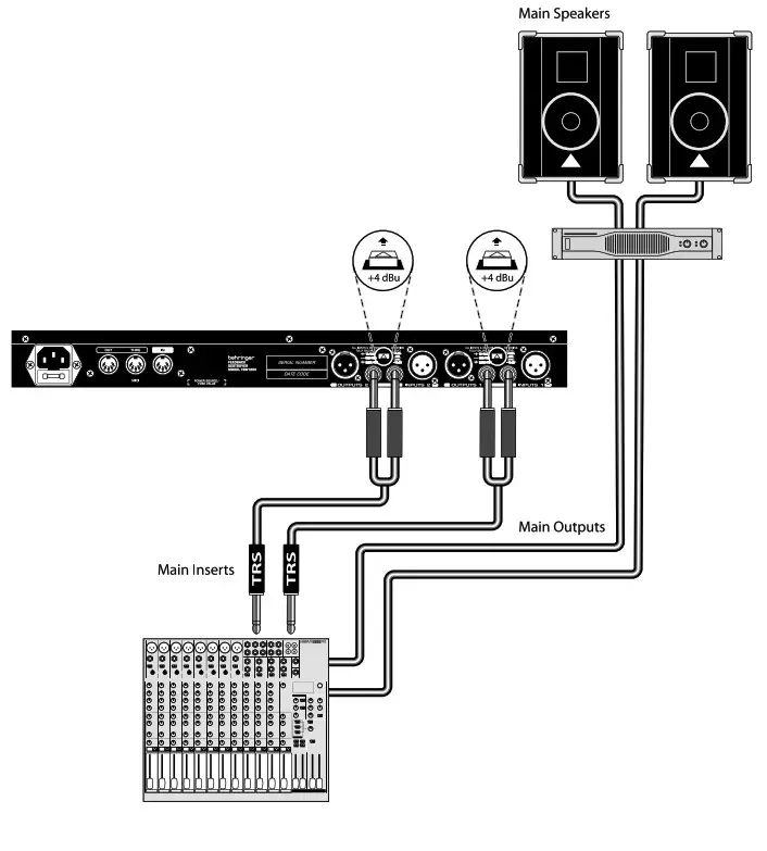
 FBQ1000 in the insert path
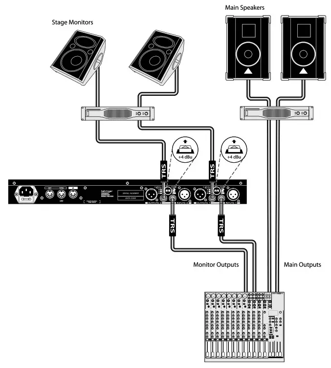
 Feedback protection for stage monitors
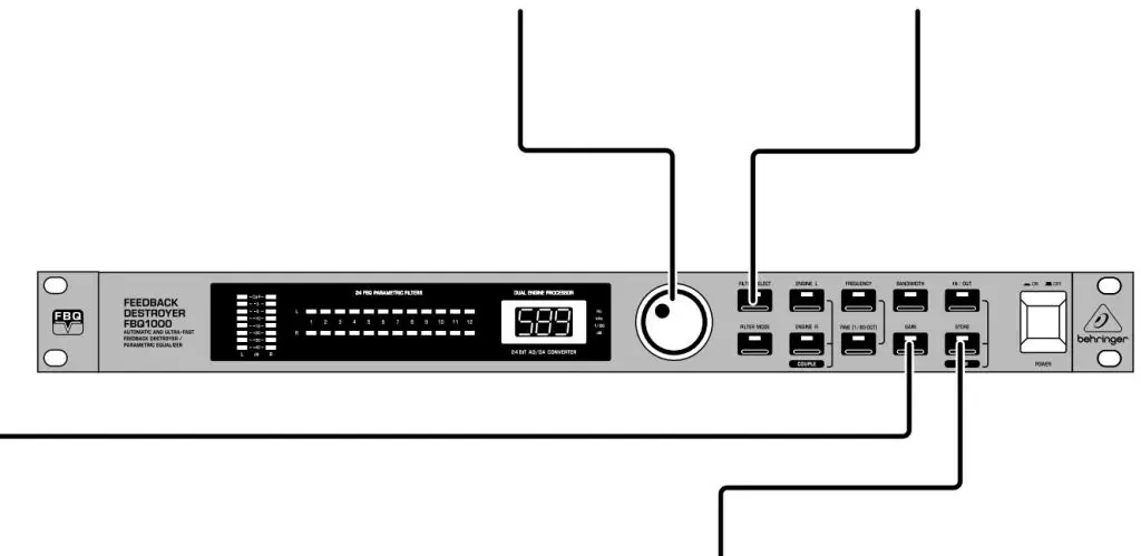
FEEDBACK DESTROYER FBQ1000 Controls
Step 2: Controls
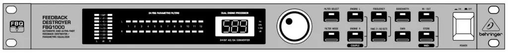
 LED METER displays the output signal level. If the CLIP LED lights frequently, lower the gain setting for the channel. In Total Bypass mode, the LED METER displays the input signal level.
STATUS LEDs display the status of the 12 individual filters for each channel. Active filters or EQs are displayed by a lit LED. A flashing LED signifies that a filter is searching for feedback frequencies. Inactive filters are displayed by an unlit LED.
 ENGINE L and R buttons select the left (L) and right (R) audio channels. Press both buttons simultaneously to enter Couple mode, which allows both channels to be edited at the same time.
FEEDBACK DESTROYER FBQ1000 Controls
Step 2: Controls
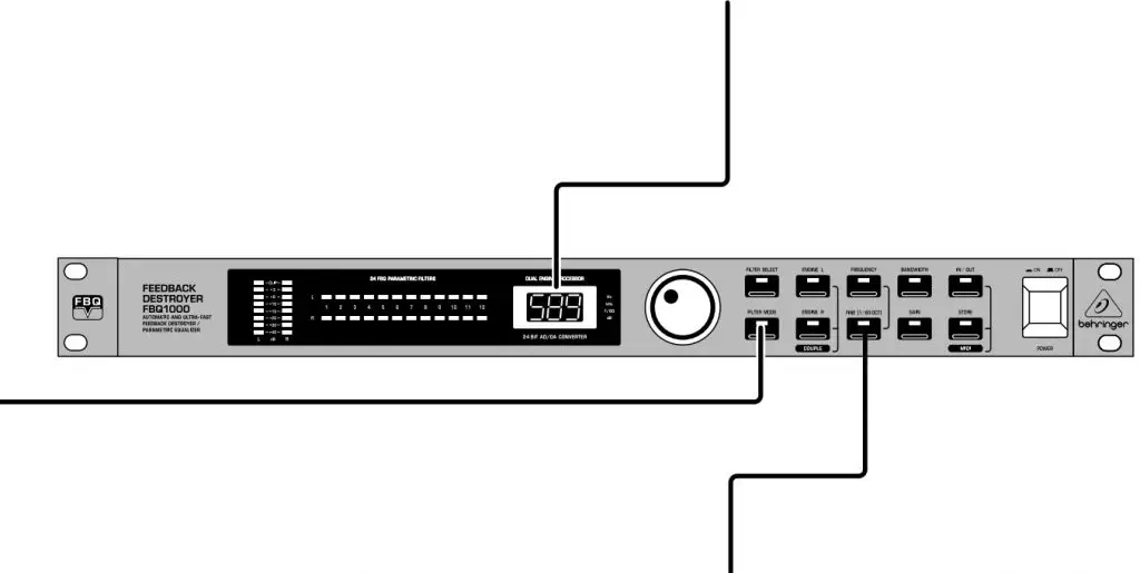
FILTER MODE button
accesses the four filter modes: Off (OF), Parametric EQ (PA), Single-Shot (SI), and Auto (AU).
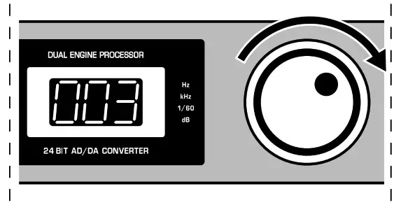
JOG WHEEL scrolls through presets and adjusts parameter values.
FINE button enables the JOG WHEEL to fine-tune the standard ISO frequencies.
FEEDBACK DESTROYER FBQ1000 Controls
Step 2: Controls
FREQUENCY button enables the JOG WHEEL to select the frequency that is to be edited in Parametric EQ mode.
BANDWIDTH button enables the JOG WHEEL to adjust the filter bandwidth (Q factor) of the≈selected filter.
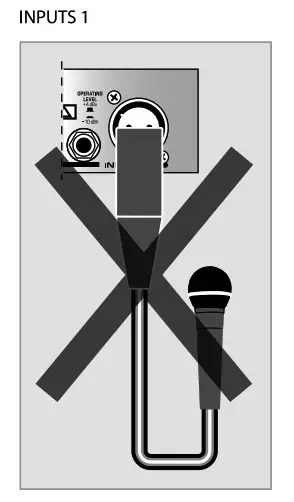
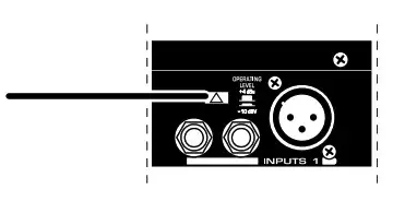
OPERATING LEVEL button switches between -10 dBV and +4 dBu, allowing the FBQ1000 to operate in its optimum range.
FEEDBACK DESTROYER FBQ1000 Controls
Step 2: Controls
GAIN button enables the JOG WHEEL to adjust the amount of boost or attenuation of the selected filter (+16 dB to -48 dB).
JOG WHEEL scrolls through presets and adjusts parameter values.
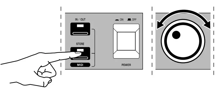 STORE button enables the JOG WHEEL to scroll through the 10 available preset slots. Press the STORE button again to confirm and save to the selected slot.
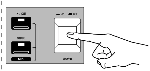
FEEDBACK DESTROYER FBQ1000 Getting started
Step 3: Getting started
-
- Use the JOG WHEEL to select preset 3. This sets all filters to Auto mode, which is a good starting point for eliminating feedback.
- Press the ENGINE L or ENGINE R button to edit a specific channel. Press both ENGINE buttons simultaneously to enter Couple mode which allows both channels to be edited at the same time.
- Press the FILTER SELECT button and turn the JOG WHEEL to select a specific filter.
- Press the FILTER MODE button and turn the JOG WHEEL to edit the type of filter.
- To save the preset, press the STORE button and turn the JOG WHEEL to select the preset location. The digit in the DISPLAY will flash.

- Press the STORE button to confirm and save.
- Log on to behringer.com to download the full manual for more details on the FBQ1000’s functionality.
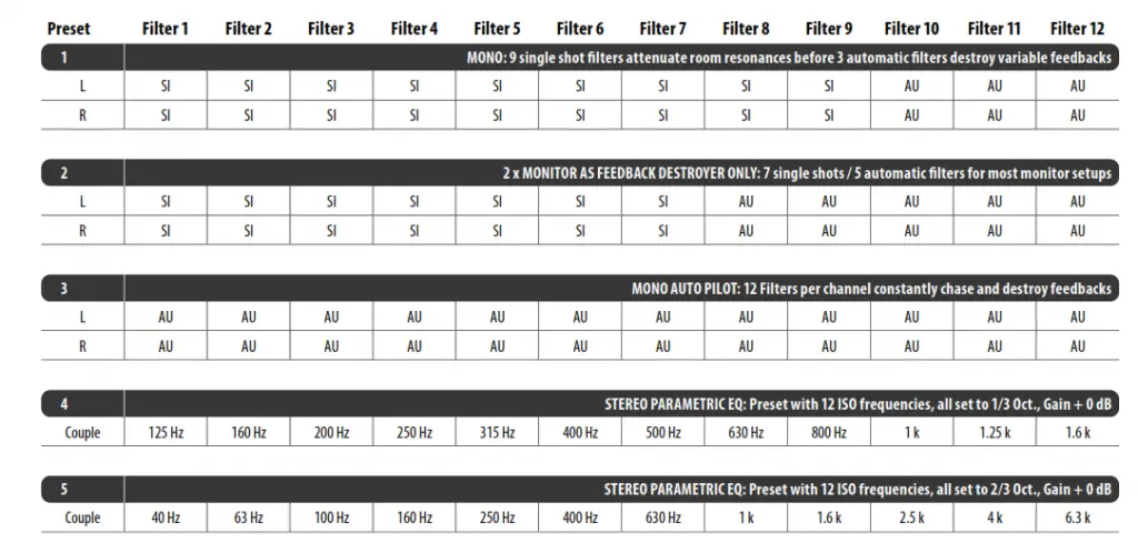
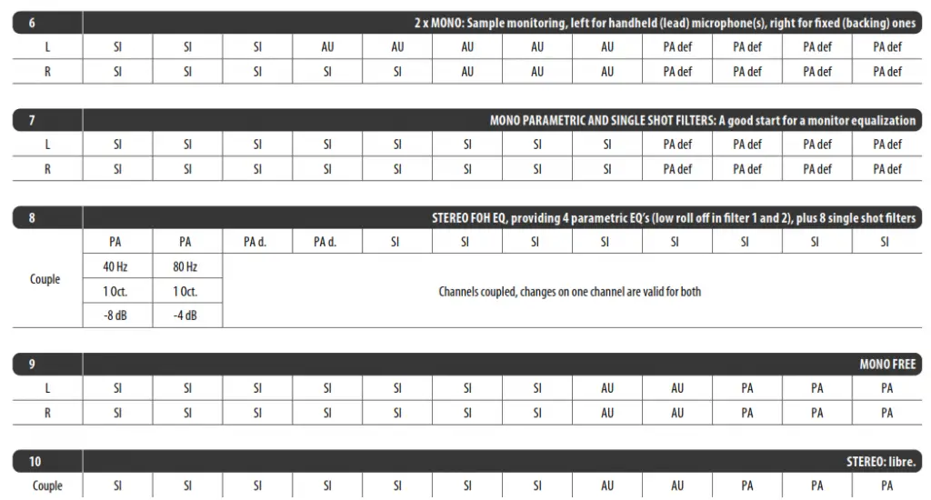
FEEDBACK DESTROYER FBQ1000 Preset chart

Specifications
| Audio Inputs | |
| Connectors | XLR and ¼” TRS |
| Type | RF-filtered, servo-balanced input |
| Impedance | 60 kΩ balanced, 30 kΩ unbalanced |
| Nominal operating level | -10 dBV to +4 dBu (switchable) |
| Max. input level | +16 dBu at +4 dBu nominal level, +2 dBV at -10 dBV nominal level |
| Audio Outputs | |
| Connectors | XLR and ¼” TRS |
| Type | Electronically servo-balanced output stage |
| Impedance | 60 kΩ balanced, 30 kΩ unbalanced |
| Max. output level | +16 dBu at +4 dBu nominal level, +2 dBV at -10 dBV nominal level |
| System Specifications | |
| Bandwidth | 20 Hz to 20 kHz, +0/-1 dB |
| Noise | > 94 dB, unweighted (20 Hz to 20 kHz) |
| THD | 0.0075% typ. @ +4 dBu, 1 kHz, Gain 1 |
| Crosstalk | < -76 dB |
| MIDI Interface | |
| Type | 5-Pin DIN Socket IN/OUT/THRU |
| Digital Processing | |
| Converters | 24-bit Sigma-Delta, 64/128-times oversampling |
| Display | |
| Type | 2 ½-digit numeric LED display |
| Power Supply | |
| Mains Voltages | |
| USA/Canada | 120 V~, 60 Hz (T 200 mA L, 250 V) |
| U.K./Australia | 240 V~, 50 Hz (T 100 mA L, 250 V) |
| Europe | 230 V~, 50 Hz (T 100 mA L, 250 V) |
| Korea | 220 V~, 60 Hz (T 100 mA L, 250 V) |
| China | 220 V~, 50 Hz (T 100 mA L, 250 V) |
| Japan | 100 V~, 50/60 Hz (T 200 mA L, 250 V) |
| Power consumption | approx. 15 Watts max. |
| Mains connection | Standard IEC receptacle |
| Physical | |
| Dimensions (H x W D) | 44 x 483 x 195 mm (1.7 x 19 x 7.7″) |
| Weight | 1.9 kg (4.22 lbs) |
FEDERAL COMMUNICATIONS COMMISSION COMPLIANCE INFORMATION
Behringer
FEEDBACK DESTROYER FBQ1000
Responsible Party Name: Music Tribe Commercial NV Inc.
Address: 5270 Procyon Street, Las Vegas NV 89118, United States
Phone Number: +1 702 800 8290
FEEDBACK DESTROYER FBQ1000
This equipment has been tested and found to comply with the limits for a Class B digital device, pursuant to part 15 of the FCC Rules. These limits are designed to provide reasonable protection against harmful interference in a residential installation. This equipment generates, uses, and can radiate radio frequency energy and, if not installed and used in accordance with the instructions, may cause harmful interference to radio communications. However, there is no guarantee that interference will not occur in a particular installation. If this equipment does cause harmful interference to radio or television reception, which can be determined by turning the equipment off and on, the user is encouraged to try to correct the interference by one or more of the following measures:
- Reorient or relocate the receiving antenna.
- Increase the separation between the equipment and receiver.
- Connect the equipment into an outlet on a circuit different from that to which the receiver is connected.
- Consult the dealer or an experienced radio/TV technician for help.
This equipment complies with Part 15 of the FCC Rules. Operation is subject to the following two conditions:
(1) This device may not cause harmful interference, and
(2) This device must accept any interference received, including interference that may cause undesired operation.
Important information:
Changes or modifications to the equipment not expressly approved by MUSIC Tribe can void the user’s authority to use the equipment.

Hereby, Music Tribe declares that this product is in compliance with Directive 2014/35/EU,
Directive 2014/30/EU, Directive 2011/65/EU and Amendment 2015/863/EU, Directive 2012/19/EU,
Regulation 519/2012 REACH SVHC and
Directive 1907/2006/EC.
Full text of EU DoC is available at https://community.musictribe.com/
EU Representative: Music Tribe Brands DK A/S
Address: Ib Spang Olsens Gade 17, DK – 8200 Aarhus N, Denmark
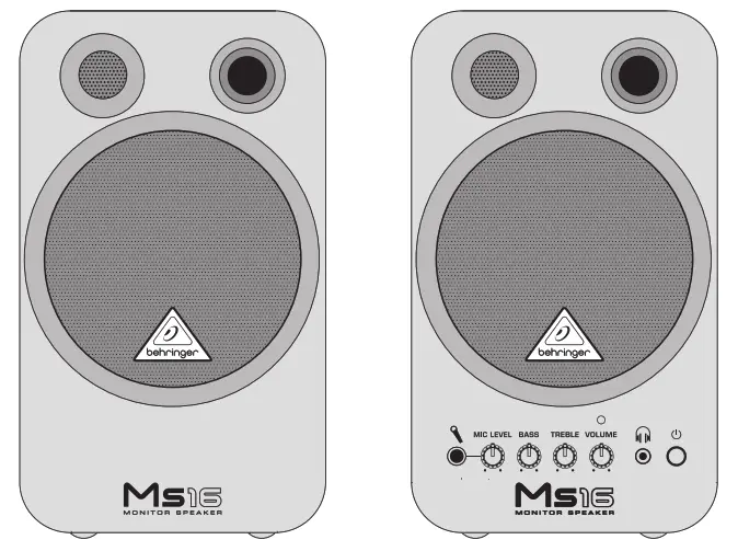
MS16
High-Performance, Active 16-Watt Personal Monitor System
Important Safety Instructions

 Terminals marked with this symbol carry electrical current of sufficient magnitude to constitute risk of electric shock. Use only high-quality professional speaker cables with ¼” TS or twist-locking plugs pre-installed. All other installation or modification should be performed only by qualified personnel.
This symbol, wherever it appears, alerts you to the presence of uninsulated dangerous voltage inside the enclosure – voltage that may be sufficient to constitute a risk of shock.
This symbol, wherever it appears, alerts you to important operating and maintenance instructions in the accompanying literature. Please read the manual.
Caution
To reduce the risk of electric shock, do not remove the top cover (or the rear section). No user-serviceable parts inside. Refer servicing to qualified personnel.
Caution
To reduce the risk of fire or electric shock, do not expose this appliance to rain and moisture. The apparatus shall not be exposed to dripping or splashing liquids and no objects filled with liquids, such as vases, shall be placed on the apparatus.
Caution
These service instructions are for use by qualified service personnel only. To reduce the risk of electric shock do not perform any servicing other than that contained in the operation instructions. Repairs have to be performed by qualified service personnel.
- Read these instructions.
- Keep these instructions.
- Heed all warnings.
- Follow all instructions.
- Do not use this apparatus near water.
- Clean only with a dry cloth.
- Do not block any ventilation openings. Install in accordance with the manufacturer’s instructions.
- Do not install near any heat sources such as radiators, heat registers, stoves, or other apparatus (including amplifiers) that produce heat.
- Do not defeat the safety purpose of the polarized or grounding-type plug. A polarized plug has two blades with one wider than the other. A grounding-type plug has two blades and a third grounding prong. The wide blade or the third prong is provided for your safety. If the provided plug does not fit into your outlet, consult an electrician for the replacement of the obsolete outlet.
- Protect the power cord from being walked on or pinched particularly at plugs, convenience receptacles, and the point where they exit from the apparatus.
- Use only attachments/accessories specified by the manufacturer.
- Use only with the cart, stand, tripod, bracket, or table specified by the manufacturer, or sold with the apparatus. When a cart is used, use caution when moving the cart/ apparatus combination to avoid injury from tip-over.
- Unplug this apparatus during lightning storms or when unused for long periods of time.
- Refer all servicing to qualified service personnel. Servicing is required when the apparatus has been damaged in any way, such as power supply cord or plug is damaged, liquid has been spilled or objects have fallen into the apparatus, the apparatus has been exposed to rain or moisture, does not operate normally, or has been dropped.
- The apparatus shall be connected to a MAINS socket outlet with a protective earthing connection.
- Where the MAINS plug or an appliance coupler is used as the disconnect device, the disconnect device shall remain readily operable.

- Correct disposal of this product: This symbol indicates that this product must not be disposed of with household waste, according to the WEEE Directive (2012/19/EU) and your national law. This product should be taken to a collection center licensed for the recycling of waste electrical and electronic equipment (EEE). The mishandling of this type of waste could have a possible negative impact on the environment and human health due to potentially hazardous substances that are generally associated with EEE. At the same time, your cooperation in the correct disposal of this product will contribute to the efficient use of natural resources. For more information about where you can take your waste equipment for recycling, please contact your local city office or your household waste collection service.
- Do not install in a confined space, such as a bookcase or similar unit.
- Do not place naked flame sources, such as lighted candles, on the apparatus.
- Please keep the environmental aspects of battery disposal in mind. Batteries must be disposed of at a battery collection point.
- Use this apparatus in tropical and/or moderate climates.
LEGAL DISCLAIMER
MUSIC Tribe accepts no liability for any loss which may be suffered by any person who relies either wholly on or in part upon any description, photograph, or statement contained herein. Technical specifications, appearances, and other information are subject to change without notice. All trademarks are the property of their respective owners. MIDAS, KLARK TEKNIK, LAB GRUPPEN, LAKE, TANNOY, TURBOSOUND, TC ELECTRONIC, TC HELICON, BEHRINGER, BUGERA and COOLAUDIO are trademarks or registered trademarks of MUSIC Tribe Global Brands Ltd. © MUSIC Tribe Global Brands Ltd. 2018 All rights reserved.
LIMITED WARRANTY
For the applicable warranty terms and conditions and additional information regarding MUSIC Tribe’s Limited Warranty, please see complete details online at musictri.be/warranty.
MONITOR SPEAKERS MS16 Controls
Controls
- MICROPHONE INPUT
(¼ ” TRS). This connector allows you to connect your dynamic microphone. - Turn the MIC LEVEL control to adjust the volume of your microphone.
- BASS control.
- TREBLE control.
- Turn the VOLUME control to adjust the volume level of the devices connected to your MS16.
- Connect your headphones via the PHONES output (1/8″ TRS) to monitor any of the input devices.
- The POWER switch turns the unit on or off .
- The POWER LED lights up when power is switched on.
- INPUT 1 (1/8″ TRS) allows you to connect audio equipment such as CD/MD players.
- Use INPUT 2 (RCA) to connect your soundcard, keyboard or expander.
- SPEAKER TO LEFT connector. Connect both speakers by using the speaker cable included in this package.
- SPEAKER FROM RIGHT connector. Insert the speaker cable from the SPEAKER TOLEFT connector.
- AC POWER input.
- SERIAL NUMBER.
Specifications
| Loudspeaker | |
| Tweeter Ø | |
| Woofer Ø | |
| Audio Inputs | |
| Input 1 | 1⁄8″ TRS stereo, input level -10 dBm, 10 kΩ |
| Input 2 | 2 2 RCA stereo, input level -10 dBm, 10 kΩ |
| Mic | ¼” TRS, input level -50 dBm, 50 Ω |
| System Specifi cations | |
| Output power | 2 x 8 Watts |
| Frequency response | 80 Hz to 20 kHz |
| Power Supply | |
| Mains Voltages | |
| USA/Canada | 120 V~, 60 Hz |
| Europe/U.K./Australia | 230 V~, 50 Hz |
| Japan | 100 V~, 50 – 60 Hz |
| General export model | 120/230 V~, 50 – 60 Hz |
| Power consumption | 0.14 x 0.28 x 0.33 A / 230 x 120 x 100 V |
| Physical | |
| Dimensions (H x W x D) | 9 ½ x 5 ½ x 5 9⁄10 ” / 241 x 140 x 150 x mm |
| Weight | 8.8 lbs / 4 kg |
BEHRINGER is constantly striving to maintain the highest professional standards. As a result of these efforts, modifications may be made from time to time to existing products without prior notice. Specifications and appearance may differ from those listed or illustrated.
Other important information
- Register online. Please register your new MUSIC Tribe equipment right after you purchase it by visiting Behringer. com. Registering your purchase using our simple online form helps us to process your repair claims more quickly and efficiently. Also, read the terms and conditions of our warranty, if applicable.
- Malfunction. Should your MUSIC Tribe Authorized Reseller not be located in your vicinity, you may contact the MUSIC Tribe Authorized Fulfiller for your country listed under “Support” at Behringer. com. Should your country not be listed, please check if your problem can be dealt with by our “Online Support” which may also be found under “Support” at Behringer. com. Alternatively, please submit an online warranty claim at Behringer. com BEFORE returning the product.
- Power Connections. Before plugging the unit into a power socket, please make sure you are using the correct mains voltage for your particular model. Faulty fuses must be replaced with fuses of the same type and rating without exception.
We Hear You
![]()
Portable
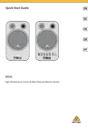
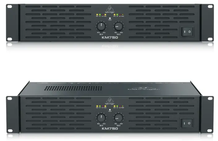
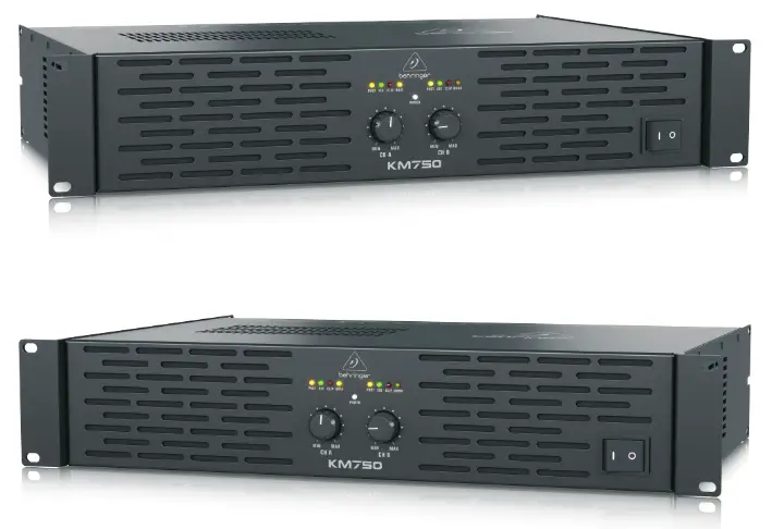
KM750
Professional 750-Watt Stereo Power Amplifier with
ATR (Accelerated Transient Response)

- 2 x 400 Watts into 4 Ohms; 2 x 200 Watts into 8 Ohms; 750 Watts into 8 Ohms (bridge mode)
- ATR (Accelerated Transient Response) technology for ultimate punch and clarity
- Switchable limiters offer maximum output level with reliable overload protection
- Precise power, signal, and Clip LEDs to monitor performance
- XLR, 1/4” TRS and RCA input connectors for compatibility with any source
- Professional speaker connectors and “touch-proof” binding posts support most speaker wiring systems
- Independent DC and short circuit protection on each channel automatically protects amplifier and speakers
- High-current toroidal transformer for ultra-high transient response and absolute reliability
- Active cooling on heatsink “Built-like-a-tank” impact-resistant, all-steel 2U rackmount chassis
- 3-Year Warranty Program
- Designed and engineered in Germany
The remarkable KM750 packs a heartstopping 750 Watts of output power into a lightweight (18.7 lbs/8.5 kg) package, thanks to our Accelerated Transient Response (ATR) technology. Ample power (750 Watts in Bridge mode; 2 x 400 Watts @ 4 Ohms; 2 x 200 Watts @ 8 Ohms) and high-tech efficiency combine, giving you a supercharged workhorse that will keep your rig kicking for years and years to come.

Accelerated Transient Response Delivers the Knockout Punch
It takes huge pulses of energy (current and voltage) to propel a woofer cone out fast enough to match a bass beat. That’s called Transient Response and it’s the holy grail of amp design. By carefully selecting transistors with extremely high slew rates and optimizing other proprietary parts of our circuitry, our amps are able to react instantly to even the most demanding electronic bass impulses. If the woofers in your PA system can keep up, your audience will hear a tighter, crisper, more natural sound. Instead of operating relatively continuously like most power amps, the KM750 features rail tracking for effectively modulating the power supply rails with only the peaks of the input signal. This technology has revolutionized pro audio amp designs with its outstanding performance and efficiency. ![]()
![]()
Sublimely Simple Operation
The front panel controls and indicators provide your system’s vital signs at a glance. After pressing the Power button, the Power LED lights to show the amp is ready for action. All channels feature positive-detent Gain controls with Signal LEDs that light when a signal is present, as well as Clip LEDs that alert to reduce the input signal.
Just as elegant as the front, the rear panel is home to balanced XLR and 1/4″ TRS, plus unbalanced 1/4″ TS and RCA connections. Take your pick of professional locking speaker Outputs or touch-proof binding posts to securely connect speakers. The same panel contains the switches that put the KM750 in Mono, Stereo (two-channel mode), or mono Bridge mode. Flick the Limiter On/Off switch to activate the built-in overload protection.

Sound Value
The remarkable KM750 power amp was built for the working musician. It is exceptionally light, packs a massive 750 Watts of output power, thanks to our Accelerated Transient Response (ATR) technology and is built rugged enough for life on the road. Plus, the KM750’s ultra-light price tag will leave cash left over for you to get more stuff to amplify! Check out the KM750 at your BEHRINGER dealer, or order yours online today!

You Are Covered
We always strive to provide the best possible Customer Experience. Our products are made in our own MUSIC Tribe factory using state-of-the-art automation, enhanced production workflows, and quality assurance labs with the most sophisticated test equipment available in the world. As a result, we have one of the lowest product failure rates in the industry, and we confidently back it up with a generous Warranty program.

 KM750
KM750
Professional 750-Watt
Stereo Power Amplifier with
ATR (Accelerated Transient Response)
KM750
Professional 750-Watt
Stereo Power Amplifier with
ATR (Accelerated Transient Response)

For service, support or more information contact the BEHRINGER location nearest you:
| Europe MUSIC Tribe Brands UK Ltd. Tel: +44156 273 2290 Email: [email protected] [email protected] [email protected] |
USA/Canada MUSIC Tribe Commercial NV Inc. Tel: +1 702 800 8290 Email: [email protected] [email protected] [email protected] |
Japan MUSIC Tribe Services JP K.K. Tel: +81 3 6231 0453 Email: [email protected] [email protected] [email protected] |
MUSIC Tribe accepts no liability for any loss which may be suffered by any person who relies either wholly or in part upon any description, photograph, or statement contained herein.
Technical specifications, appearances, and other information are subject to change without notice. All trademarks are the property of their respective owners. MIDAS, KLARK TEKNIK, LAB GRUPPEN, LAKE, TANNOY, TURBOSOUND, TC ELECTRONIC, TC HELICON, BEHRINGER, BUGERA, and COOLAUDIO are trademarks or registered trademarks of MUSIC Tribe Global Brands Ltd. © MUSIC Tribe Global Brands Ltd. 2018 All rights reserved.
Welcome to Behringer
Thank you for showing your confidence in us by purchasing the Behringer MICROPHONE PP400, a compact phono preamplifier.
Turntables have low-level signals. However, most audio units can only process line-level signals. Between a turntable and another audio unit (a mixer, an amplifier, or a recording unit), the PP400 acts as an intermediary, as follows:
- The PP400 equalizes a turntable signal according to RIAA specifications.
- The PP400 amplifies the RIAA equalized signal.
- The PP400 outputs a line-level signal.
![]() Please read the safety instructions that appear at the end of this document.
Please read the safety instructions that appear at the end of this document.
Connectors and Control Elements
This section illustrates and describes each PP400 connector and control element.
(2) Fig. 1: PP400 connectors and control elements![]()
V 5.0 A50-00002-78890
- 12 V connector: To connect the power supply unit to the PP400, use the 12 V connector. Connecting the power supply unit to the mains automatically switches the PP400 on. To disconnect the unit from the mains, pull out the main cord plug.
- ON LED: As soon as the unit is connected to the mains, the ON LED is illuminated.
- INPUT (L and R) connectors: To send a turntable signal to the PP400, you need an RCA audio cable (stereo). Use this cable to connect:
• the left output on the turntable to the L (left) INPUT on the PP400
• the right output on the turntable to the R (right) INPUT on the PP400
The PP400 can output a line-level signal via one of the following connectors:
• RCA ((4) OUTPUT L and R)
• ¼” TRS ((5) OUTPUT)
 Do not simultaneously use both PP400 OUTPUTs.
 - OUTPUT (L and R) connectors: To use these RCA connectors, you need an RCA audio cable (stereo). Use this audio cable to connect:
• the L (left) OUTPUT on the PP400 to the left input on the amplifier, recording unit, or mixer. (On a mixer, use a CD or TAPE input.)
• the R (right) OUTPUT on the PP400 to the right input on the amplifier, recording unit, or mixer - OUTPUT connector: To use this ¼”, TRS (stereo) connector, you need an audio cable. Use the audio cable to connect the PP400 OUTPUT to an input on the mixer, amplifier, or recording unit. One end of this audio cable must include a ¼”, TRS connector. If the input on the mixer, amplifier, or recording unit is:
• stereo, the other end of the audio cable must include a ¼”, TRS connector
• mono, the other end of the audio cable must include 2 TS connectors (one for each mono input)
SERIAL NUMBER: To register your unit, use the serial number that is located on the bottom of the PP400.
Setup Example
The following is an example of how to set up the PP400:
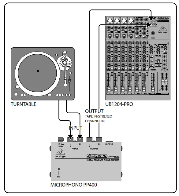
Fig 2: PP400 setup example
Important Safety Instructions
- Read these instructions.
- Keep these instructions.
- Heed all warnings.
- Follow all instructions.
- Do not use this apparatus near water.
- Clean only with dry cloth.
- Do not block any ventilation openings. Install in accordance with the manufacturer’s instructions.
- Do not install near any heat sources such as radiators, heat registers, stoves, or other apparatus (including amplifiers) that produce heat.
- Do not defeat the safety purpose of the polarized or grounding-type plug. A polarized plug has two blades with one wider than the other. A grounding-type plug has two blades and a third grounding prong. The wide blade or the third prong are provided for your safety. If the provided plug does not fit into your outlet, consult an electrician for replacement of the obsolete outlet.
- Protect the power cord from being walked on or pinched particularly at plugs, convenience receptacles, and the point where they exit from the apparatus.
- Only use attachments/accessories specified by the manufacturer.
- Use only with the cart, stand, tripod, bracket, or table specified by the manufacturer, or sold with the apparatus. When a cart is used, use caution when moving the cart/apparatus combination to avoid injury from tip-over.
- Unplug this apparatus during lightning storms or when unused for long periods of time.
- Refer all servicing to qualified service personnel. Servicing is required when the apparatus has been damaged in any way, such as power supply cord or plug is damaged, liquid has been spilled or objects have fallen into the apparatus, the apparatus has been exposed to rain or moisture, does not operate normally, or has been dropped.
Specifications
| Input | |
| Type | RCA connector |
| Impedance | approx. 47 kΩ |
| Max. input level | -23.5 dBV @ 1kHz |
| Output | |
| Type | RCA and ¼” TRS, stereo connectors |
| Impedance | approx. 50 Ω |
| Max. output level | +11.5 dBV @ 1 kHz |
| System Specifications | |
| Frequency response | RIAA |
| THD | 0.06% typ. @ -40 dBu/1 kHz |
| Gain | 35 dB |
| Signal-to-noise ratio | 68 dBu @ 0 dBu, A-weighted |
| Input sensitivity | 5.3 mV @ 1 kHz |
| Power Supply | |
| Mains connection | external power supply, 12 V / 150 mA |
| Mains Voltage | |
| USA/Canada | 120 V~, 60 Hz |
| China/Korea | 220 V~, 50 Hz |
| U.K./Australia | 240 V~, 50 Hz |
| Europe | 230 V~, 50 Hz |
| Japan | 100 V~, 50 – 60 Hz |
| Power consumption | approx. 1.5 W |
| Dimensions/Weight | |
| Dimensions (H x D x W) | approx. 1 ¼ x 4 x 2 ½” approx. 32 x 103 x 64 mm |
| Weight | approx. 0.40 lbs / 0.180 kg |
Behringer is constantly striving to maintain the highest professional standards. As a result of these efforts, modifications may be made from time to time to existing products without prior notice. Specifications and appearance may differ from those listed or illustrated.
LEGAL DISCLAIMER
Music Tribe accepts no liability for any loss which may be suffered by any person who relies either wholly or in part upon any description, photograph,
or statement contained herein. Technical specifications, appearances and other information are subject to change without notice. All trademarks are the
property of their respective owners. Midas, Klark Teknik, Lab Gruppen, Lake, Tannoy, Turbosound, TC Electronic, TC Helicon, Behringer, Bugera, Oberheim, Auratone and Coolaudio are trademarks or registered trademarks of Music Tribe Global Brands Ltd. © Music Tribe Global Brands Ltd. 2021 All rights reserved.
LIMITED WARRANTY
For the applicable warranty terms and conditions and additional information regarding Music Tribe’s Limited Warranty, please see complete details online at musictribe.com/warranty.
![]()
Operation Ambient Temperature up to 45°C
Hereby, Music Tribe declares that this product is in compliance with Directive 2014/35/EU, Directive 2014/30/EU, Directive 2011/65/EU and Amendment 2015/863/EU, Directive 2012/19/EU, Regulation 519/2012 REACH SVHC and Directive 1907/2006/EC.
Full text of EU DoC is available at https://community.musictribe.com/
EU Representative: Music Tribe Brands DK A/S
Address: Ib Spang Olsens Gade 17, DK – 8200 Aarhus N, Denmark
![]()
TUBE ULTRAGAIN MIC100
Audiophile Vacuum Tube Preamplifier with Limiter
![]()
2
Important Safety Instructions
 CAUTION
RISK OF ELECTRIC SHOCK!
DO NOT OPEN!
Terminals marked with this symbol carry electrical current of sufficient magnitude to constitute risk of electric shock. Use only high-quality professional speaker cables with ¼” TS or twist-locking plugs pre-installed. All other installation or modification should be performed only by qualified personnel.
This symbol, wherever it appears, alerts you to the presence of uninsulated dangerous voltage inside the enclosure – voltage that may be sufficient to constitute a risk of shock.
This symbol, wherever it appears, alerts you to important operating and maintenance instructions in the accompanying literature. Please read the manual.
Caution
To reduce the risk of electric shock, do not remove the top cover (or the rear section). No user serviceable parts inside. Refer servicing to qualified personnel.
Caution
To reduce the risk of fire or electric shock, do not expose this appliance to rain and moisture. The apparatus shall not be exposed to dripping or splashing liquids and no objects filled with liquids, such as vases, shall be placed on the apparatus.
Caution
These service instructions are for use by qualified service personnel only. To reduce the risk of electric shock do not perform any servicing other than that contained in the operation instructions. Repairs have to be performed by qualified service personnel.
1. Read these instructions.
2. Keep these instructions.
3. Heed all warnings.
4. Follow all instructions.
5. Do not use this apparatus near water.
6. Clean only with dry cloth.
7. Do not block any ventilation openings. Install in accordance with the manufacturer’s instructions.
8. Do not install near any heat sources such as radiators, heat registers, stoves, or other apparatus (including amplifiers) that produce heat.
9. Do not defeat the safety purpose of the polarized or grounding-type plug. A polarized plug has two blades with one wider than the other. A grounding-type plug has two blades and a third grounding prong. The wide blade or the third prong are provided for your safety. If the provided plug does not fit into your outlet, consult an electrician for replacement of the obsolete outlet.
10. Protect the power cord from being walked on or pinched particularly at plugs, convenience receptacles, and the point where they exit from the apparatus.
11. Use only attachments/accessories specified by the manufacturer.
 12. Use only with the cart, stand, tripod, bracket, or table specified by the manufacturer, or sold with the apparatus. When a cart is used, use caution when moving the cart/ apparatus combination to avoid injury from tip-over.
13. Unplug this apparatus during lightning storms or when unused for long periods of time.
14. Refer all servicing to qualified service personnel. Servicing is required when the apparatus has been damaged in any way, such as power supply cord or plug is damaged, liquid has been spilled or objects have fallen into the apparatus, the apparatus has been exposed to rain or moisture, does not operate normally, or has been dropped.
15. The apparatus shall be connected to a MAINS socket outlet with a protective earthing connection.
16. Where the MAINS plug or an appliance coupler is used as the disconnect device, the disconnect device shall remain readily operable.
17. Correct disposal of this product: This symbol indicates that this product must not be disposed of with household waste, according to the WEEE Directive (2012/19/ EU) and your national law. This product should be taken to a collection center licensed for the recycling of waste electrical and electronic equipment (EEE). The mishandling of this type of waste could have a possible negative impact on the environment and human health due to potentially hazardous substances that are generally associated with EEE. At the same time, your cooperation in the correct disposal of this product will contribute to the efficient use of natural resources. For more information about where you can take your waste equipment for recycling, please contact your local city office, or your household waste collection service.
18. Do not install in a confined space, such as a book case or similar unit.
19. Do not place naked flame sources, such as lighted candles, on the apparatus.
20. Please keep the environmental aspects of battery disposal in mind. Batteries must be disposed-of at a battery collection point.
21. Use this apparatus in tropical and/or moderate climates.
LEGAL DISCLAIMER
MUSIC Tribe accepts no liability for any loss which may be suffered by any person who relies either wholly or in part upon any description, photograph, or statement contained herein. Technical specifications, appearances and other information are subject to change without notice. All trademarks are the property of their respective owners. MIDAS, KLARK TEKNIK, LAB GRUPPEN, LAKE, TANNOY, TURBOSOUND, TC ELECTRONIC, TC HELICON, BEHRINGER, BUGERA and COOLAUDIO are trademarks or registered trademarks of MUSIC Tribe Global Brands Ltd. © MUSIC Tribe Global Brands Ltd. 2018 All rights reserved.
LIMITED WARRANTY
For the applicable warranty terms and conditions and additional information regarding MUSIC Tribe’s Limited Warranty, please see complete details online at musictri.be/warranty.a
Side panel of the MIC100

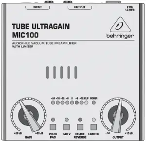
User interface of the MIC100
Controls
- Use the POWER SUPPLY CONNECTOR to hook up the enclosed power supply unit. Next to this connector you’ll find the strain relief clamp, which prevents accidental release of the power supply.
- This is the balanced XLR OUTPUT of your MIC100. Use this connector to feed the XLR input of your mixing console, multitrack recorder or power amp.
- The balanced ¼” TRS OUTPUT of your MIC100 can also be connected to either mixer, recording system or power amp.
- The balanced ¼” TRS INPUT of your MIC100 can be used to connect your electric guitar, for example. This input is wired parallelly to the XLR input.
- Use the balanced XLR INPUT to connect your microphone.
◊ In contrast to its outputs, the MIC100’s inputs should never be used simultaneously! - The GAIN control allows applying gain from +26 to +60 dB to the input signal. This control should be set fully counterclockwise when (dis)connecting a sound source to the MIC100. When all connections are made, slowly start raising gain.
- We recommend using the LED meter to adjust gain. The LED chain displays the output signal level in dB. Please make sure that the clip LED never lights up permanently. It should light up only at peak signals, but never all the time.
- If your MIC100 is connected to the mains via the enclosed power supply unit, the POWER LED lights up to indicate that your MIC100 is running.
- The 20 dB PAD button reduces the input sensitivity by 20 dB. The appropriate setting depends on the equipment connected. No matter what your application is, the clip LED warns you to reduce the gain setting, so as to avoid distortion.
- This +48 V switch activates the phantom power supply for the XLR input. Phantom power supply is required for operating condenser microphones.
- With the PHASE REVERSE switch, the input signal is reversed by 180°. This function is available for both mic and line signals. Use this function in a multi-microphone setup if you detect phase cancellations in specifi c frequency bands.
- Use the LIMITER switch to limit the signal and to prevent distortion.
- The OUTPUT control governs the output level of the device within a range from –∞ to +10 dB. If the control is set fully counter-clockwise, there is no output signal at all. The more the control is set clockwise, the higher the output level.
| Audio Inputs | |
| XLR Input | |
| Connector | balanced/unbalanced |
| Type | transformerless, DC-decoupled input |
| Impedance | approx. 2 kΩ |
| Max. input level | +7 dBu / -20 dB with pad |
| ¼” TRS Input | |
| Connector | balanced/unbalanced |
| Type | transformerless, DC-decoupled input |
| Impedance | approx. 1 MΩ |
| Max. input level | +16 dBu / -20 dB with pad |
| Audio Outputs | |
| Connectors | XLR connector + ¼” TRS jack
balanced/unbalanced |
| Type | transformerless, DC-decoupled output |
| Impedance | approx. 700 Ω balanced / 350 Ω unbalanced |
| Max. output level | approx. +26 dBu @ 100 kΩ |
| Frequency Response | |
| Mic input | <10 Hz to 43 kHz (±3 dB) |
| Line input | <10 Hz to 40 kHz (±3 dB) |
| Function Controls | |
| GAIN | variable ( +26 dB to +60 dB) |
| OUTPUT | variable ( -∞ to +10 dB) |
| Function Switches | |
| 20 dB PAD | level attenuation (20 dB) |
| +48 V | activates the phantom power |
| PHASE REVERSE | Phase reverse (180°) |
| LIMITER | limits the output signal |
| Indicators | |
| Input Level | 8-segment LED meter:
-24, -18, -12, -6, 0, +6, +12, Clip |
| Power LED | indicates operation |
| Power Supply | |
| Adapter | PSU |
| Mains Voltage | |
| USA/Canada | 120 V~, 60 Hz |
| Europe/U.K./Australia | 230 V~, 50 Hz |
| China | 220 V~, 50 Hz |
| Korea | 220 V~, 60 Hz |
| Japan | 100 V~, 50 / 60 Hz |
| Dimensions | |
| Dimensions (H x W x D) | 64 x 135 x 135 mm (2.5 x 5.3 x 5.3″) |
| Weight | 1.0 kg (2.2 lbs) |
BEHRINGER is constantly striving to maintain the highest professional standards. As a result of these efforts, modifications may be made from time to time to existing products without prior notice. Specifications and appearance may differ from those listed or illustrated.
- Register online. Please register your new MUSIC Tribe equipment right after you purchase it by visiting behringer.com. Registering your purchase using our simple online form helps us to process your repair claims more quickly and efficiently. Also, read the terms and conditions of our warranty, if applicable.
- Malfunction. Should your MUSIC Tribe Authorized Reseller not be located in your vicinity, you may contact the MUSIC Tribe Authorized Fulfiller for your country listed under “Support” at behringer.com. Should your country not be listed, please check if your problem can be dealt with by our “Online Support” which may also be found under “Support” at behringer.com. Alternatively, please submit an online warranty claim at behringer.com BEFORE returning the product.
We Hear You
![]()
DDM4000
Important Safety Instructions
![]()
- Read these instructions.
- Keep these instructions.
- Heed all warnings.
- Follow all instructions.
- Do not use this apparatus near water.
- Clean only with dry cloth.
- Do not block any ventilation openings. Install in accordance with the manufacturer’s instructions.
- Do not install near any heat sources such as radiators, heat registers, stoves, or other apparatus (including amplifiers) that produce heat.
- Do not defeat the safety purpose of the polarized or grounding-type plug. A polarized plug has two blades with one wider than the other. A grounding-type plug has two blades and a third grounding prong. The wide blade or the third prong are provided for your safety. If the provided plug does not fit into your outlet, consult an electrician for replacement of the obsolete outlet.
- Protect the power cord from being walked on or pinched particularly at plugs, convenience receptacles, and the point where they exit from the apparatus.
 Use only attachments/accessories specified by the manufacturer.
- Use only with the cart, stand, tripod, bracket, or table specified by the manufacturer, or sold with the apparatus. When a cart is used, use caution when moving the cart/apparatus combination to avoid injury from tip-over.
- Unplug this apparatus during lightning storms or when unused for long periods of time.
- Refer all servicing to qualified service personnel. Servicing is required when the apparatus has been damaged in any way, such as power supply cord or plug is damaged, liquid has been spilled or objects have fallen into the apparatus, the apparatus has been exposed to rain or moisture, does not operate normally, or has been dropped.
- The apparatus shall be connected to a MAINS socket outlet with a protective earthing connection.
- Where the MAINS plug or an appliance coupler is used as the disconnect device, the disconnect device shall remain readily operable.
 Correct disposal of this product: This symbol indicates that this product must not be disposed of with household waste, according to the WEEE Directive (2012/19/EU) and your national law. This product should be taken to a collection center licensed for the recycling of waste electrical and electronic equipment (EEE). The mishandling of this type of waste could have a possible negative impact on the environment and human health due to potentially hazardous substances that are generally associated with EEE. At the same time, your cooperation in the correct disposal of this product will contribute to the efficient use of natural resources. For more information about where you can take your waste equipment for recycling, please contact your local city office, or your household waste collection service.
- Do not install in a confined space, such as a book case or similar unit.
- Do not place naked flame sources, such as lighted candles, on the apparatus.
- Please keep the environmental aspects of battery disposal in mind. Batteries must be disposed-of at a battery collection point.
- This apparatus may be used in tropical and moderate climates up to 45°C.
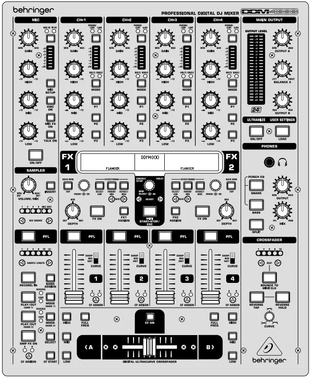
DIGITAL PRO MIXER DDM4000 Controls

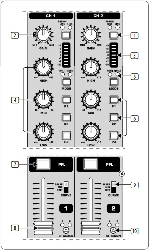
- Stereo channels 1 – 4

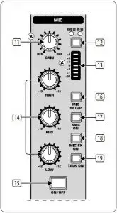
- Microphone channel

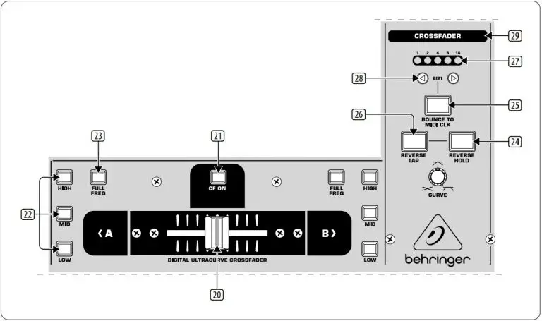
- Crossfader section
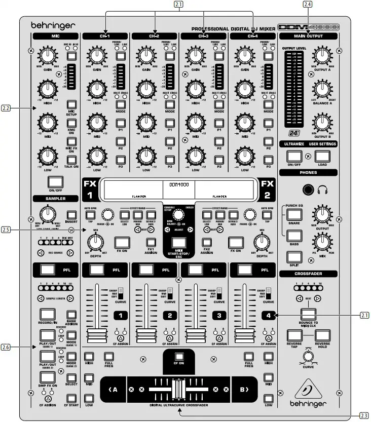
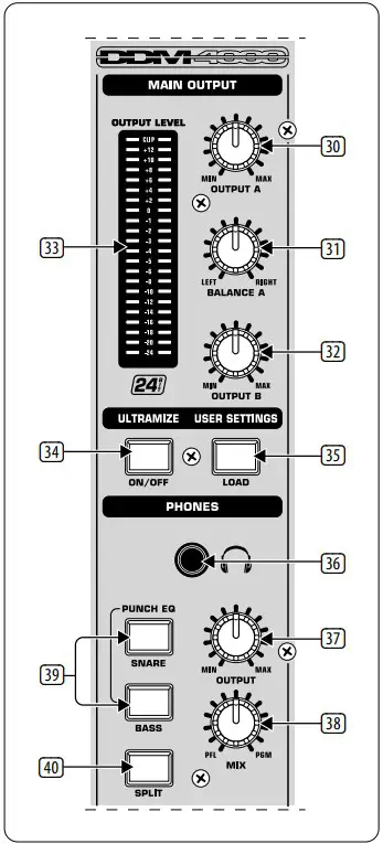
- Main and phones section
- Sampler
- BPM and effects section
Controls
- The input select switch lets you switch between two signal sources. Select Line to hear the signal of the Line input (67). Select Phono/Line to listen to the incoming source signal at the Phono/Line (68) input.
- The GAIN knob adjusts the level of the input signal. The actual level is displayed on the level meter (3).
- The 7-segment LED meter indicates the level of the input signal.
- Each input channel features a 3-band equalizer (HIGH, MID and LOW) with kill feature, giving you up to 12 dB of boost and a maximum cut of -∞ dB (kill). The kill feature lets you mute the given frequency range. When each EQ knob is turned fully left, the signal is effectively muted. All EQ parameters can be adjusted in Channel Setup.
- The MODE push button changes the functionality of the preset push button
- from Multi to Single.
- The preset push buttons P1, P2 and P3 allow you to store and activate equalizer presets. When activated in Single Mode, these push buttons provide a maximum cut of -∞ dB (kill function).
- Press the PFL push button to listen in on the channel’s signal using headphones.
- The fader controls the channel volume.
- The CURVE switch adjusts the response of the fader. In SOFT Mode, the fader responds slower to steady fader movement in the upper range and quicker in the lower range. In SHARP Mode, the fader adjusts the volume quicker in the upper third and slower in the lower range. In MID Mode, the fader responds in a linear fashion. Since a difference in volume levels is heard when switching between modes, don’t use this switch while playing music!
- The CF ASSIGN push button lets you determine on which side of the crossfader (20) (A or B) the signal is to be heard.
- The GAIN knob adjusts the level of the microphone signal at the MIC 1 input.
- This switch determines which signal is to be displayed on the level meter (13). IN VU shows the unprocessed input level which helps you to adjust the microphone signal correctly. XMC VU shows the level after it has passed the Ultramic processor.
- The 7-segment LED meter indicates the level of the microphone channel.
- The microphone channel strip features a 3-band equalizer (HIGH, MID and LOW). The range is ±12 dB.
- The ON/OFF push button turns the microphone channel on and off.
- The MIC SETUP push button opens the Mic Setup menu on the display. This allows you to adjust the settings of the equalizer, the Ultramic processor and the MIC FX (effects processor).
- The XMC ON push button activates the ULTRAMIC processor, which includes a 2-band compressor and expander. Ultramic settings can be adjusted in Mic Setup.
- The MIC FX ON push button activates the microphone effects processor. Select the effect in Mic Setup.
- The TALK ON push button activates the Talkover function. This attenuates the volume level of the music as soon as you speak into the microphone. This is a very useful function to make yourself heard over the music being played. You can adjust all the relevant settings in Talk Setup.
- The replaceable crossfader is used to fade between the signals that are assigned to its two sides A and B. You can assign the stereo channels and sampler using the CF Assign push buttons (10) and (65).
- The CF ON push button activates the crossfader. When the push button is not pressed, the signals of the individual channels are routed straight to the Main outputs.
- There are 3 Kill push buttons (HIGH, MID and LOW) on each side of the crossfader which let you mute the given frequency range. In Crossfader Setup, it is possible to activate a special X-OVER mode that enhances the crossfader’s functionality in combination with the Kill push buttons.
- Press the FULL FREQ push button to remove any frequency cuts of the KILL EQ (22).
- The CURVE knob lets you seamlessly adjust the response of the crossfader. The REVERSE function allows you to reverse the configuration of the crossfader. This way you can toggle between Channel A and B at the flick of a switch.
- REVERSE HOLD activates a permanent Reverse function. The crossfader fades between sides A and B in the reverse direction. This means that A is now on the right and B on the left side.
- REVERSE TAP activates a momentary Reverse function. This means that A and B are interchanged as long as the TAP push button is held down.
- Press the BOUNCE TO MIDI CLK push button to activate the bouncing. Once the push button is pressed, the signal repeatedly jumps from A to B and back again corresponding to the interval pre-selected by using the BEAT push buttons (28).
- The BEAT push buttons let you determine the Bounce rate, which can range between one and 16 beats.
- These LEDs indicate the number of beats you have chosen.
- The OUTPUT A knob controls the volume of output A ((73)).
- The BALANCE knob adjusts the stereo panning of output A.
- The OUTPUT B knob controls the volume of output B ((74)).
- The high-resolution, 22-segment OUTPUT LEVEL meter indicates the level of the output signal on OUTPUT A.
- ULTRAMIZE ON/OFF push button:The Ultramizer is an effect that enhances the loudness and assertiveness by dynamic compression. In Ultramizer Setup, you can configure the Ultramizer.
- The LOAD push button lets you load the user settings of the entire mixer. The settings that are active when the device is turned off are loaded when the device is switched back on again.
- Connect the headphones to the PHONES jack (1/4″ TRS connector).
- The OUTPUT knob controls the volume of the head-phones.
- The MIX knob adjusts the balance between PFL signal and PGM signal (PFL = Pre Fader Listening, fader independent pre-listening of individual channels; PGM = Program, Master signal). When the knob is turned completely to the left, you only hear the PFL signal, whereas when turned completely to the right the Master signal is heard. Between these two positions, you can adjust the mix of both signals.
- The PUNCH EQ function helps synchronize two tracks. You can orient yourself to the snare or the bass drum or both. Press the SNARE or BASS push button to emphasize the selected sound in the headphones.
- When the SPLIT push button is pressed, the PFL signal is heard in the left headphone and the PGM signal is only heard in the right headphone.
- The graphic display shows BPM values, effect names and effect parameters as well as channel assignments. It also leads you through Console Setup.
- The FX ON push button activates the effects unit.
- Press the FX ASSIGN push button to assign an effects unit to a signal source (push button flashes). The possible input sources are listed on the display. Select the preferred source by turning and pressing the PARAMETER knob (45).
- The DEPTH knob adjusts the effect intensity (depth). For some effects, it also lets you adjust the mix between the original signal (dry) and the effect signal (wet).
- Press the PARAM (eter) knob to select the effect parameters. By turning the knob, you can change the parameter shown on the display.
- Press SELECT/LOW to access the effects list (on the display). Turn and press the knob (45) to load a preset.
- Press the PARAM/MID push button to access the effect parameters. Turn the knob (45) to change the parameter value.
- Press DEFAULT/HIGH to restore a preset.
- Depending on the selected effect, the BEAT push buttons can adjust time related parameters. However, the values entered are not in milliseconds or similar units, but in beats.
- To enter the tempo manually, tap this push button (at least 2x) in the rhythm of the music (TAP). By keeping the AUTO BPM/TAP push button pressed a little longer (> 1 s), the automatic tempo input (AUTO BPM) is reactivated.
- Turn the CONSOLE SETUP knob to adjust the tempo of the MIDI Clock (press and turn simultaneously = coarse adjustment). A short press on the knob confirms the entry made. A long press on the knob lets you access Console Setup.
- The MIDI START/STOP/ESC turns on the MIDI Clock.
- The ADJUST push buttons let you transfer the tempo of the BPM counter to the MIDI Clock.
- Press the INSERT push button to add the sampler signal to the channel (Insert Mode). If the push button is not activated, the sampler is mixed to the selected channel (Mix Mode). In both cases, playback is initiated with the REC SOURCE push buttons. When the sampler is routed to the crossfader, the LED of the INSERT push button goes out.
- The VOLUME/MIX knob controls the volume of the sampler (in Mix Mode) as well as the volume balance between input signal and Sampler (in Insert Mode).
- The REC SOURCE push buttons let you select the channel for recording and playing back samples.
- Press the PFL push button to listen in on the sampler signal with the headphones.
- SAMPLE LENGTH adjusts the recording time (1–16 beats or endless recording ∞).
- RECORD/IN lets you record to the Sampler. Select a bank beforehand. By pressing the push button a second time, the recording is stopped (only in ∞ Mode).
- BANK ASSIGN is used to select a bank in which the recorded material is stored. The selected bank is indicated by the relevant MODE push button (61) which signalizes the readiness to record.
- The MODE push buttons (Bank 1 and Bank 2) are used to select the sampler’s types of playback (Reverse and Loop). A short tap activates or deactivates the Reverse function; pressing the push button a little longer activates or deactivates the Loop function.
- Press the PLAY/OUT push button to start the playback of the recorded sample. When the Loop function is deactivated, the sample is only played back as long as the PLAY push button is pressed.
- Press SMP FX ON push button to activate the Brake effect.
- Press the SELECT push button to determine the length of the brake (1, 4 or 8 Beat Brake, which is shown in the center of the display).
- The CF ASSIGN push button lets you determine on which side of the crossfader the sampler signal is to be routed to.
- You can even trigger the sampler with the crossfader when the sampler is assigned to it. To order to do so, simply press the CF START push button. But beforehand, use BANK ASSIGN to select the bank that should be played back when using the fader.
- The LINE inputs are used to connect the Line signals (for example, CD players, sound cards and drum machines).
- The PHONO inputs let you connect turntables.
- Use the PHONO/LINE switches to set the PHONO inputs to Line level in order for you to be able to connect a CD player to the PHONO inputs.
- The GND connectors are used to ground the turntables.
- The balanced XLR connectors provide a connection for dynamic microphones.
- This is the LEVEL control for the MIC 2 input.
- These are the OUT A outputs (XLR) allowing you to connect to an amplifier. Use the OUTPUT A control (30) to adjust the volume level. Additionally, the SUBWOOFER output lets you hook up a subwoofer. A crossover is integrated into the DDM4000. The crossover frequency is adjusted in Output Setup.
- The MAIN OUT connector panel consists of OUT A, OUT B and TAPE outputs.
- DIGITAL OUT is the digital output of the DDM4000. This is where you find the TAPE signal in CD quality (16 bit/44.1 kHz).
- These are the MIDI IN, MIDI OUT and MIDI THRU connectors that allow you to connect external MIDI equipment and synchronize with their MIDI Clock.
- Power is supplied via an IEC connector. The matching cable is provided with the unit.
- FUSE RETAINER/VOLTAGE SELECTOR.
- Use the POWER switch to turn on the DDM4000. Before connecting the unit to the power mains, ensure that the POWER switch is in OFF position. When the unit is in operation, ensure that the mains plug is accessible.
Specifications
| Audio Inputs | |
| Mic 1/2 (XLR, Electronically Balanced) | |
| Max. input level | -14 dBu |
| Input impedance | 2 kΩ |
| Phono (RCA) | |
| Max. input level | -18 dBu |
| Input impedance | 47 kΩ |
| Line (RCA) | |
| Max. input level | +30 dBu |
| Input impedance | 15 kΩ |
| Audio Outputs | |
| Max. output level | +21 dBu |
| Output impedance | 200 Ω |
| OUT A/OUT B/TAPE (RCA) | |
| Max. output level | +21 dBu |
| Output impedance | 100 Ω |
| Phones Out | max. 260 mW @ 100 Ω / 1% THD |
| S/PDIF | (coaxial, 16 bit, 44.1 kHz) |
| Equalizer | |
| Stereo Low | -∞ dB/+12 dB |
| Stereo Mid | -∞ dB/+12 dB |
| Stereo High | -∞ dB/+12 dB |
| Mic Low | -12 dB/+12 dB, Shelving |
| Mic Mid | -12 dB/+12 dB, Peak |
| Mic High | -12 dB/+12 dB, Shelving |
| Digital Effects Processor | |
| DSP | 2x Analog Devices Black Fin |
| AD/DA converter | 24-bit Sigma-Delta
128-times oversampling/Cirrus |
| Sampling rate | 44.1 kHz |
| LCD display | 320 x 40 pixel |
| MIDI Interface | 5-pin DIN jacks In/Out/Thru |
| System Specifications | |
| Frequency Response | |
| Mic | 25 Hz – 20 kHz, +0/-3 dB |
| Phono | 20 Hz – 20 kHz, +0/-3 dB |
| Line | 20 Hz – 20 kHz, +0/-3 dB |
| Signal-to-Noise Ratio | |
| Mic | > 87 dB |
| Phono | > 83 dB |
| Line | > 102 dB |
| Distortion (THD) | < 0,009% (Line – OUT A) |
| Crosstalk | < -80 dB / 1 kHz (Line) |
| Power Supply | |
| Mains Voltage/Fuse | |
| 100 – 240 V~, 50/60 Hz | T 1 A H 250 V |
| Power Consumption | max. 20 W |
| Mains Connector | standard IEC receptacle |
| Dimensions/Weight | |
| Dimensions (H x W x D) |
|
| Weight | approx. 12.3 lbs / 5.6 kg |
Other important information
- Register online. Please register your new MusicTribe equipment right after you purchase it by visiting musictribe.com. Registering your purchase using our simple online form helps us to process your repair claims more quickly and efficiently. Also, read the terms and conditions of our warranty, if applicable.
- Malfunction. Should your MusicTribe Authorized Reseller not be located in your vicinity, you may contact the MusicTribe Authorized Fulfiller for your country listed under “Support” at musictribe.com. Should your country not be listed, please check if your problem can be dealt with by our “Online Support” which may also be found under “Support” at musictribe.com. Alternatively, please submit an online warranty claim at musictribe.com BEFORE returning the product.
- Power Connections. Before plugging the unit into a power socket, please make sure you are using the correct mains voltage for your particular model. Faulty fuses must be replaced with fuses of the same type and rating without exception.
LEGAL DISCLAIMER
Music Tribe accepts no liability for any loss which may be suffered by any person who relies either wholly or in part upon any description, photograph, or statement contained herein. Technical specifications, appearances and other information are subject to change without notice. All trademarks are the property of their respective owners. Midas, Klark Teknik, Lab Gruppen, Lake, Tannoy, Turbosound, TC Electronic, TC Helicon, Behringer, Bugera, Oberheim, Auratone and Coolaudio are trademarks or registered trademarks of Music Tribe Global Brands Ltd. © Music Tribe Global Brands Ltd. 2021 All rights reserved.
LIMITED WARRANTY
For the applicable warranty terms and conditions and additional information regarding Music Tribe’s Limited Warranty, please see complete details online at musictribe.com/warranty.
FEDERAL COMMUNICATIONS COMMISSION COMPLIANCE INFORMATION
Behringer DIGITAL PRO MIXER DDM400
Responsible Party Name: Music Tribe Commercial NV Inc.
Address: 5270 Procyon Street, Las Vegas NV 89118, United States
Phone Number: +1 702 800 8290
DIGITAL PRO MIXER DDM4000
This equipment has been tested and found to comply with the limits for a Class B digital device, pursuant to part 15 of the FCC Rules. These limits are designed to provide reasonable protection against harmful interference in a residential installation. This equipment generates, uses and can radiate radio frequency energy and, if not installed and used in accordance with the instructions, may cause harmful interference to radio communications. However, there is no guarantee that interference will not occur in a particular installation. If this equipment does cause harmful interference to radio or television reception, which can be determined by turning the equipment off and on, the user is encouraged to try to correct the interference by one or more of the following measures:
- Reorient or relocate the receiving antenna.
- Increase the separation between the equipment and receiver.
- Connect the equipment into an outlet on a circuit different from that to which the receiver is connected.
- Consult the dealer or an experienced radio/TV technician for help.
This device complies with Part 15 of the FCC rules. Operation is subject to the following two conditions:
- this device may not cause harmful interference, and
- this device must accept any interference received, including interference that may cause undesired operation.
Important information:
Changes or modifications to the equipment not expressly approved by Music Tribe can void the user’s authority to use the equipment.
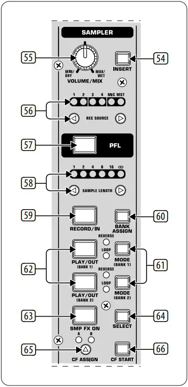
Hereby, Music Tribe declares that this product is in compliance with Directive 2014/35/EU,Directive 2014/30/EU, Directive 2011/65/EU and Amendment 2015/863/
EU, Directive 2012/19/EU, Regulation 519/2012 REACH SVHC and Directive 1907/2006/EC.
Full text of EU DoC is available at https://community.musictribe.com/
EU Representative: Music Tribe Brands DK A/S
Address: Ib Spang Olsens Gade 17, DK – 8200 Aarhus N, Denmark

Important Safety Instructions

 Terminals marked with this symbol carry electrical current of sufficient magnitude to constitute risk of electric shock.
Use only high-quality professional speaker cables with ¼” TS or twist-locking plugs pre-installed. All other installation or modification should be performed only by qualified personnel.
This symbol, wherever it appears, alerts you to the presence of uninsulated dangerous voltage inside the enclosure – voltage that may be sufficient to constitute a risk of shock.
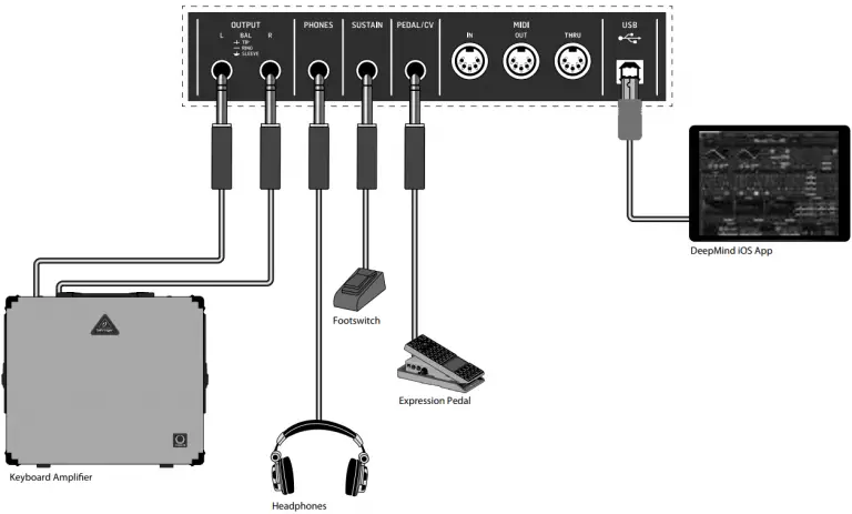 This symbol, wherever it appears, alerts you to important operating and maintenance instructions in the accompanying literature. Please read the manual.
Caution
To reduce the risk of electric shock, do not remove the top cover (or the rear section).
No user serviceable parts inside. Refer servicing to qualified personnel.
Caution
To reduce the risk of fire or electric shock, do not expose this appliance to rain and moisture. The apparatus shall not be exposed to dripping or splashing liquids and no objects filled with liquids, such as vases, shall be placed on the apparatus.
Caution
These service instructions are for use by qualified service personnel only.
To reduce the risk of electric shock do not perform any servicing other than that contained in the operation instructions. Repairs have to be performed by qualified service personnel.
1. Read these instructions.
2. Keep these instructions.
3. Heed all warnings.
4. Follow all instructions.
5. Do not use this apparatus near water.
6. Clean only with dry cloth.
7. Do not block any ventilation openings. Install in accordance with the manufacturer’s instructions.
8. Do not install near any heat sources such as radiators, heat registers, stoves, or other apparatus (including amplifiers) that produce heat.
9. Do not defeat the safety purpose of the polarized or grounding-type plug. A polarized plug has two blades with one wider than the other. A grounding-type plug has two blades and a third grounding prong. The wide blade or the third prong are provided for your safety. If the provided plug does not fit into your outlet, consult an electrician for replacement of the obsolete outlet.
10. Protect the power cord from being walked on or pinched particularly at plugs, convenience receptacles, and the point where they exit from the apparatus.
11. Use only attachments/accessories specified by the manufacturer.
12. Use only with the cart, stand, tripod, bracket, or table specified by the manufacturer, or sold with the apparatus. When a cart is used, use caution when moving the cart/apparatus combination to avoid injury from tip-over.
13. Unplug this apparatus during lightning storms or when unused for long periods of time.
14. Refer all servicing to qualified service personnel.
Servicing is required when the apparatus has been damaged in any way, such as power supply cord or plug is damaged, liquid has been spilled or objects have fallen into the apparatus, the apparatus has been exposed to rain or moisture, does not operate normally, or has been dropped.
15. The apparatus shall be connected to a MAINS socket outlet with a protective earthing connection.
16. Where the MAINS plug or an appliance coupler is used as the disconnect device, the disconnect device shall remain readily operable.
17. Correct disposal of this product: This symbol indicates that this product must not be disposed of with household waste, according to the WEEE Directive (2012/19/EU) and your national law. This product should be taken to a collection center licensed for the recycling of waste electrical and electronic equipment (EEE). The mishandling of this type of waste could have a possible negative impact on the environment and human health due to potentially hazardous substances that are generally associated with EEE. At the same time, your cooperation in the correct disposal of this product will contribute to the efficient use of natural resources. For more information about where you can take your waste equipment for recycling, please contact your local city office, or your household waste collection service.
18. Do not install in a confined space, such as a book case or similar unit.
19. Do not place naked flame sources, such as lighted candles, on the apparatus.
20. Please keep the environmental aspects of battery disposal in mind. Batteries must be disposed-of at a battery collection point.
21. This apparatus may be used in tropical and moderate climates up to 45°C.
LEGAL DISCLAIMER
Music Tribe accepts no liability for any loss which may be suffered by any person who relies either wholly or in part upon any description, photograph, or statement contained herein. Technical specifications, appearances and other information are subject to change without notice. All trademarks are the property of their respective owners. Midas, Klark Teknik, Lab Gruppen, Lake, Tannoy, Turbosound, TC Electronic, TC Helicon, Behringer, Bugera, Oberheim, Auratone and Coolaudio are trademarks or registered trademarks of Music Tribe Global Brands Ltd. © Music Tribe Global Brands Ltd. 2021 All rights reserved.
LIMITED WARRANTY
For the applicable warranty terms and conditions and additional information regarding Music Tribe’s Limited Warranty, please see complete details online at musictribe.com/warranty.
Hook-Up
Studio System

Live System
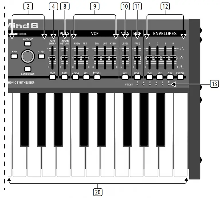
Band / Practice System
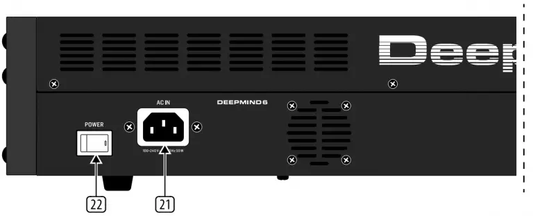
Controls


- DISPLAY – this large backlit LCD screen shows the synthesizer status, parameters, and the five main menus. The contrast and brightness are adjustable on the PANEL SETTINGS page of the GLOBAL menu.
- NAVIGATION – navigate within the display menus using the UP, DOWN, +/YES and -/NO buttons.
- MENUS – these switches allow access to the display menus.
PROG MENU- the main display of the synthesizer. Shows the current program, the currently adjusted parameter and a visual representation of the parameter and the three envelopes.
FX MENU – add up to four effects from the list available. Change the effects routing by selecting one of the ten MODEs available.
Each of the effects has individual controls for all parameters.
GLOBAL MENU – view and adjust settings for the synthesizer. There are five pages, CONNECTIVITY, KEYBOARD, PEDAL, PANEL and SYSTEM.
COMPARE MENU – in this menu, you can compare the current program with the stored program and see the difference in physical fader positions.
WRITE MENU – in this menu, you can write the current program settings to the program library. You can also rename the program and set its category type. - DATA ENTRY – selected parameters on the display are adjusted using the rotary knob or the fader. The rotary knob has a click which allows very accurate control. The fader allows rapid adjustment across the full range.
MOD- this switch opens the modulation matrix on the display and allows up to 8 modulations to be created from the list of sources and destinations. - ARP/SEQ – this area controls the arpeggiator and the control sequencer.
ON/OFF – when activated, this generates an arpeggio based on pressed keys. Note – the control sequencer is turned on from its edit page only.
RATE – adjusts the rate of the arpeggiator / sequencer in beats per minute (BPM).
GATE TIME – adjusts the duration of the note played based on a percentage of the time between triggered notes.
CHORD – allows you to play any chord with a single key. The chord is given a root note and mapped across the keyboard.
POLY CHORD – allows you to play multiple chords from multiple keys. The chords are mapped to individual keys.
TAP/HOLD – tap this button in time with your performance to set the rate/BPM, or press and hold to engage the HOLD function.
EDIT – this allows additional arpeggiator/ control sequencer parameters to be edited from the main display. - LFO 1 and 2- low frequency oscillators used to modulate or control other parameters.
RATE- this sets the rate, or speed of the LFO.
DELAY TIME – the duration of time which will elapse before the LFO starts.
EDIT – this allows additional LFO parameters to be edited from the main display.
LFO WAVEFORMs – these LEDs indicate the type and status of the waveforms produced by each LFO. - OSC 1 & 2 – These analog full range oscillators create waveforms which are the sound source of the synthesizer.
OSC 1 & 2 PITCH MOD – amount of pitch modulation applied to respective OSC.
OSC 1 SQUAREWAVE– this switch turns the square wave output for OSC 1 on/off.
OSC 1 PWM – amount of pulse width modulation applied to the OSC 1 square wave.
OSC 1 SAWTOOTH- this switch turns the sawtooth output for OSC 1 on/off.
OSC 2 TONE MOD- amount of tone modulation applied to OSC 2.
OSC 2 PITCH- controls the base pitch of OSC 2.
OSC 2 LEVEL- controls the level of OSC 2.
NOISE LEVEL- controls the amount of white noise added to the oscillators.
EDIT- this allows additional OSC parameters to be edited from the main display. - POLY – this area is used to control the polyphony of the synthesizer.
UNISON DETUNE – when voices are playing in unison, this adjusts the amount of detuning between the voices.
EDIT- this allows additional POLY parameters to be edited from the main display. - VCF – the voltage controlled low pass filter used to filter high frequencies from the sound of the synthesizer.
FREQ – adjusts the cut-off frequency of the filter.
2-POLE – changes the roll off slope of the filter from the default 4-POLE mode to a 2-POLE mode.
RES – adjusts the resonance of the filter cut-off point.
EDIT – allows additional VCF parameters to be edited from the main display.
ENV – adjusts the level of the VCF ENVELOPE which controls the filter cut-off frequency.
INVERT – used to invert the polarity of the VCF envelope applied to the filter cut-off frequency.
LFO – adjusts the depth of the selected
LFO waveform applied to the filter cut-off frequency.
KYBD – adjusts the amount of keyboard tracking to be applied to the filter cut-off frequency. - VCA – the voltage controlled amplifier used to control the output level.
LEVEL – controls the output level of the VCA.
EDIT – this allows additional VCA parameters to be edited from the main display. - HPF – the voltage controlled high pass filter used to filter low frequencies from the sound of the synthesizer.
FREQ – used to adjust the frequency of the high pass filter.
BOOST – this switch applies a +12 dB bass boost to the signal path. - ENVELOPE – these are the three envelopes used to modulate other parameters.
A [ATTACK]- controls the attack time of the envelope.
D [DECAY] – controls the decay time of the envelope.
S [SUSTAIN] – controls the sustain level of the envelope.
R [RELEASE] – controls the release time of the envelope.
VCA – selects the envelope used to control the voltage controlled amplifier.
VCF – selects the envelope used to control the voltage controlled filter.
MOD – selects the envelope used for user specific modulation.
CURVES – changes the ADSR controls to affect the associated curves for each stage of the envelope. - VOICES – these LEDs show which voices are active as keys are played.
- OCTAVE – these LEDs show the octave shift applied to the keyboard.
- PORTAMENTO – changes the slide time between played notes.
- VOLUME – controls the output level of the synthesizer.
- OCTAVE UP/DOWN – raise or lower the keyboard’s pitch range in steps of an octave.
- PITCH BEND WHEEL – this spring loaded wheel allows you to lower / raise the pitch expressively.
- MOD WHEEL – used for expressive modulation of parameters.
- KEYS – 37 semi-weighted full-size keys featuring expressive velocity and after-touch.
- POWER INPUT – connect using the supplied
power cable only. - POWER SWITCH – use this to turn the synthesizer on and off. Only turn it on after all connections have been made.
- OUTPUT L / R – this is the main output of the synthesizer. It should be connected to your audio interface or sound system. Remember to turn your monitors / loudspeakers on last when turning on your system and turn your monitors / loudspeakers off first when turning your system off.
- PHONES – the headphones output of the synthesizer follows the main output. Connect your headphones here. Ensure the volume control is at minimum when putting on headphones or when turning the synthesizer on or off.
- SUSTAIN – this ¼” TS jack allows you to connect a sustain pedal, such as a normally open switch.
The operation of this pedal can be customized using the GLOBAL / PEDAL SETTINGS menu. - PEDAL/CV – this ¼” TRS jack allows you to connect an expression pedal. The operation of this pedal can be customized using the GLOBAL / PEDAL SETTINGS menu.
- MIDI IN – this 5-pin DIN jack receives MIDI data from an external source. This will commonly be an external hardware sequencer, a computer equipped with a MIDI interface, etc.
- MIDI OUT – this 5-pin DIN jack sends MIDI data to an external source. This will commonly be an external hardware sequencer, a computer equipped with a MIDI interface, etc.
- MIDI THRU – this 5-pin DIN jack is used to pass through MIDI data received at the MIDI INPUT. This will commonly be sent to another synthesizer or drum machine assigned to a different DEVICE ID, or MIDI Channel.
- USB PORT – this USB type B jack allows connection to a computer. The DeepMind 6 will show up as a class-compliant USB MIDI device, capable of supporting MIDI in and out. The DeepMind 6 does not require any additional drivers to work with Windows, Android, MacOS and iOS devices.
USB MIDI IN – accepts incoming MIDI data from an application.
USB MIDI OUT – sends MIDI data to an application.
Getting started
OVERVIEW
This ‘Getting Started Guide’ will help you set up the DeepMind 6 analog polyphonic synthesizer and briefly introduce its capabilities.
CONNECTION
To connect the DeepMind 6 to your system please consult the connection guide earlier in this document.
BROWSING PROGRAMS
To change programs, use the -NO and +/YES switches. To access the program browser press and hold the PROG switch, then press the GLOBAL switch, or move the rotary knob. For more information on program management please consult the product manual.
PROGRAMMING
The DeepMind 6 programming techniques are described in detail in the product manual.
RECORD, EDIT and PLAYBACK AUTOMATION
When using the analog engine of the synthesizer with a Digital Audio Workstation (DAW) you can record and playback any automatable parameter. This allows you to record expressive automation and playback or edit that automation in your DAW.
USING AS A CONTROLLER
When using the synthesizer features as a controller you can control your virtual instruments and Digital Audio Workstation (DAW) with the accurate touch and feel of a high quality keyboard, 1 rotary potentiometer, 26 slide faders, and 33 backlit switches. For mapping please consult the product manual.
SOFTWARE SET-UP
The DeepMind 6 is a USB Class Compliant MIDI device, and so no driver installation is required. The DeepMind 6 does not require any additional drivers to work with Windows, Android, MacOS and iOS devices.
HARDWARE SETUP
Make all the connections in your system. Apply power to the DeepMind 6 using the supplied power cable only. Ensure your sound system is turned down. Turn on the power switch.
DAW SETTINGS
In your DAW, create a new channel and select the DeepMind 6 as the MIDI input device. On the same channel ensure that recorded MIDI is also sent back by making the DeepMind 6 the same channel’s MIDI output device. If you can’t see the DeepMind 6 in your DAW channel options please consult your DAW documentation to ensure you have enabled the DeepMind 6 as a MIDI device.
GLOBAL SETTINGS
The GLOBAL menus allow you to customize the DeepMind 6 analog polyphonic synthesizer to your specific workflow / requirements. For more information on the GLOBAL settings, please consult the product manual.
FIRMWARE UPDATE
Check that the latest firmware in your unit is up to date (see the GLOBAL/SYSTEM SETTINGS menu of the display). If not, then updating the firmware will give you the latest enhancements. Visit our website behringer.com, and download the latest firmware from the DeepMind 6 analog polyphonic synthesizer product page.
 IMPORTANT NOTE: Updating the firmware may affect your programs, please ensure you make a full back up. For detailed instructions please consult the product manual.
Specifications
| Global | |
| Display | Backlit LCD |
| Main Menus | PROG, FX, GLOBAL, COMPARE, WRITE |
| Edit Menus | ARP/SEQ, LFOs, OSCs, POLY, VCF, VCA, VCA ENV, VCF ENV, MOD ENV, MOD MATRIX |
| Presets | 8 banks each with 128 programs |
| Fader Modes | MIDI CC, NRPN, OFF |
| Controls | |
| Keyboard | 37 semi-weighted, full-size keys |
| Keyboard sensing | After touch and note on/off velocity |
| Encoders | 1 rotary knob |
| Faders | 26 slide faders (35 mm) |
| Switches | 33 backlit switches |
| Modulation | Free moving wheel |
| Pitch Bend | Spring loaded wheel |
| Connectivity | |
| MIDI In/Out/Thru | 5-pin DIN / 16 channels |
| Pedal/CV | ¼” TRS |
| Sustain | ¼” TS |
| USB | USB 2.0, type B |
| Output L/R | ¼” TRS, balanced, max. +18 dBu |
| Headphones | ¼” TRS, unbalanced, max. +21 dBu |
| Synthesizer Architecture | |
| Number of voices | 6 analog |
| OSC | 2 per voice |
| LFO | 2 per voice |
| VCF | 2-pole / 4-pole |
| HPF (Common to all voices) | 6 dB per octave |
| Envelopes | VCA, VCF, MOD |
| Mod Matrix | 25 sources / 133 destinations |
| Digital Effects | |
| FX Slots | 4 per Program |
| FX Types | 35 Algorithms |
| Internal effects engines | 1 true stereo SHARC DSP |
| Effects signal processing | 32/40-bit floating point @ 48 kHz |
| A/D-D/A performance | 24-bit 48 kHz, 114 dB dynamic range |
| Bypass | True hard bypass |
| USB | |
| Type | Class compliant USB 2.0, type B |
| Supported operating systems | Windows 7 or higher** Mac OS X 10.6.8 or higher iOS 8 or higher (iPad) Android 6.0 or higher |
| Power Requirements | |
| Mains connector | Standard IEC receptacle |
| Power consumption | 5°C – 40°C (41°F – 104°F) |
| Internal Switch-mode PSU | Auto range 100-240 V, (50/60 Hz) |
| Environmental | |
| Operating temperature range | 5°C – 40°C (41°F – 104°F) |
| Physical (Packaged) | |
| Dimensions (H x W x D) | 103 x 649 x 257 mm |
| Weight | 6.9 kg |
| Shipping Weight | 9.0 kg |
Important Information
- Register online. Please register your new MusicTribe equipment right after you purchase it by visiting musictribe.com. Registering your purchase using our simple online form helps us to process your repair claims more quickly and efficiently. Also, read the terms and conditions of our warranty, if applicable.
- Malfunction. Should your MusicTribe Authorized Reseller not be located in your vicinity, you may contact the MusicTribe Authorized Fulfiller for your country listed under “Support” at musictribe.com. Should your country not be listed, please check if your problem can be dealt with by our “Online Support” which may also be found under “Support” at musictribe.com. Alternatively, please submit an online warranty claim at musictribe.com BEFORE returning the product.
- Power Connections. Before plugging the unit into a power socket, please make sure you are using the correct mains voltage for your particular model.
Faulty fuses must be replaced with fuses of the same type and rating without exception.
FEDERAL COMMUNICATIONS COMMISSION COMPLIANCE INFORMATION
Responsible Party Name: Music Tribe Commercial NV Inc.
Address: 5270 Procyon Street, Las Vegas NV 89118, United States
Phone Number: +1 702 800 8290
DeepMind 6
This equipment has been tested and found to comply with the limits for a Class B digital device, pursuant to part 15 of the FCC Rules. These limits are designed to provide reasonable protection against harmful interference in a residential installation. This equipment generates, uses and can radiate radio frequency energy and, if not installed and used in accordance with the instructions, may cause harmful interference to radio communications. However, there is no guarantee that interference will not occur in a particular installation. If this equipment does cause harmful interference to radio or television reception, which can be determined by turning the equipment off and on, the user is encouraged to try to correct the interference by one or more of the following measures:
- Reorient or relocate the receiving antenna.
- Increase the separation between the equipment and receiver.
- Connect the equipment into an outlet on a circuit different from that to which the receiver is connected.
- Consult the dealer or an experienced radio/TV technician for help.
This device complies with Part 15 of the FCC rules. Operation is subject to the following two conditions:
(1) this device may not cause harmful interference, and
(2) this device must accept any interference received, including interference that may cause undesired operation.
Important information:
Changes or modifications to the equipment not expressly approved by Music Tribe can void the user’s authority to use the equipment.
![]()
Hereby, Music Tribe declares that this product is in compliance with Directive 2014/35/EU,Directive 2014/30/EU, Directive 2011/65/EU and Amendment 2015/863/ EU, Directive 2012/19/EU, Regulation 519/2012 REACH SVHC and Directive 1907/2006/EC.
Full text of EU DoC is available at https://community.musictribe.com/
EU Representative: Music Tribe Brands DK A/S
Address: Ib Spang Olsens Gade 17, DK – 8200 Aarhus N, Denmark
